
Related Manuals for Rosemount 751

Summary of Contents for Rosemount 751
- Page 1 Reference Manual 00809-0100-4378, Rev CE February 2014 Rosemount 751 Field Signal Indicator...
- Page 3 Read this manual before working with the product. For personal and system safety, and for optimum product performance, make sure you thoroughly understand the contents before installing, using, or maintaining this product. Within the United States, Rosemount Inc. has two toll-free assistance numbers: Customer Central Technical support, quoting, and order-related questions.
-
Page 5: Table Of Contents
Reference Manual Table of Contents 00809-0100-4378, Rev CE February 2014 1Section 1: Introduction LCD display ............3 Analog meter . -
Page 7: 1Section 1: Introduction
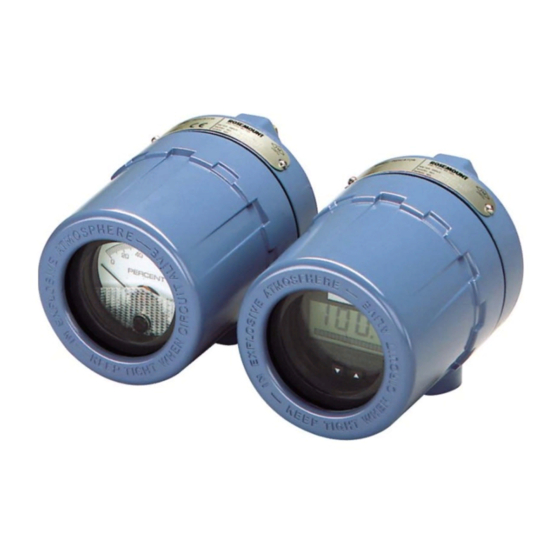
Product recycling/disposal ........... page 5 The Rosemount 751 Field Signal Indicators provide a means of displaying important process variables. -
Page 8: Analog Meter
Reference Manual Section 1: Introduction 00809-0100-4378, Rev CE February 2014 Analog meter The analog meter requires an analog 4–20 mA dc, 10–50 mA dc, or 40–200 mV dc transmitter output from a two-wire transmitter. Several meter calibration options are available to suit the requirements of a particular application. -
Page 9: Service Support
Reference Manual Section 1: Introduction 00809-0100-4378, Rev CE February 2014 Service support To expedite the return process outside of the United States, contact the nearest Emerson Process Management representative. Within the United States, call the Emerson Process Management Instrument and Valves Response Center using the 1-800-654-RSMT (7768) toll-free number. -
Page 11: 2Section 2: Installation
LCD display configuration ........... . page 11 Assembly The Rosemount 751 Field Signal Indicator is comprised of the components shown in Figure 2-1. - Page 12 Reference Manual Section 2: Installation 00809-0100-4378, Rev CE February 2014 Figure 2-2. LCD display exploded view A. Retaining Straps B. Mounting Screw into Housing C. Washer for Retaining Strap D. Mounting Screws into Mounting Plate E. Terminal Screws (2) F. Mounting Plate G.
-
Page 13: Wiring Diagrams
Rosemount transmitters. Use shielded cable for best results in electrically noisy environments. It is recommended that the 751 indicator be wired in a series configuration when the 4-20 mA transmitter does not contain a test terminal. The 751 is designed so the analog or LCD display can be removed from the housing without impacting the integrity of the 4-20 mA loop. - Page 14 00809-0100-4378, Rev CE February 2014 It is recommended that the 751 indicator be wired in a parallel configuration when the 4-20 mA transmitter includes a test terminal. Utilization of the test terminal is required in a parallel configuration. Connecting the 751 indicator across the positive and negative terminals of the 4-20 mA transmitter could impact the loop.
-
Page 15: Lcd Display Configuration
Reference Manual Section 2: Installation 00809-0100-4378, Rev CE February 2014 LCD display configuration The 20-segment bar graph is factory calibrated and represents 4–20 mA directly, but the end points of the LCD display are user-definable. The meter requires a current between 4 and 20 mA in order to be scaled, but the actual value of the current is not significant. -
Page 16: Store The Information
Reference Manual Section 2: Installation 00809-0100-4378, Rev CE February 2014 2.3.3 Store the information Press both configuration buttons simultaneously for two seconds. Note The meter displays “- -” for approximately 7.5 seconds while the information is being stored. 2.3.4 Set the display equivalent to a 4 mA signal Press the left configuration button for two seconds. -
Page 17: Aappendix A: Reference Data
Reference Manual Appendix A: Reference Data 00809-0100-4378, Rev CE February 2014 Appendix A Reference data Housing specifications ............page 13 LCD display specifications . -
Page 18: Lcd Display Specifications
Reference Manual Appendix A: Reference Data 00809-0100-4378, Rev CE February 2014 LCD display specifications A.2.1 Functional specifications Input signal 4–20 mA dc Display 4 mA point limits –999 to 1000 20 mA point limits -999 to 9999 The sum of the 4 mA point and span must not exceed 9999. Adjustments are made using non-interactive zero and span buttons. -
Page 19: Performance Specifications
Appendix A: Reference Data Reference Manual February 2014 00809-0100-4378, Rev CE Response time Responds to changes in input within a maximum of two update periods. If the filter is activated, then the display responds to the change within nine update periods. Voltage drop 0.7 Vdc typical, 1.0 Vdc maximum A.2.2... -
Page 20: Analog Meter Specifications
Reference Manual Appendix A: Reference Data 00809-0100-4378, Rev CE February 2014 Analog meter specifications A.3.1 Functional specifications Input signal 4–20 mA dc 10–50 mA dc 40–200 mV Note Maximum series resistance is ten ohms for ammeters. Meter indication 0 to 100% linear scale 0 to 100% flow scale Special optional ranges... -
Page 21: Dimensional Drawings
Appendix A: Reference Data Reference Manual February 2014 00809-0100-4378, Rev CE Dimensional drawings Figure A-1. Dimensional Drawing 3.75 (95) (71) Optional Mounting Bracket (152) (127) (104) .37 (9.4) Diameter Holes (typically four places) (178) (25) Optional (107) Mounting Bracket Permanent (76) (28) (102) -
Page 22: Ordering Information
Mounting Bracket for Flat Surface or 2-inch Pipe Reducer Stainless Steel Reducer ¾- to ½-in. for Conduit Connection (See Figure 1 for reference.) Bar code tag Customer Specified Barcode Tag Typical model number: 751 A M1 NA BC (1) May be reconfigured in the field. Reference Data... - Page 23 Appendix A: Reference Data Reference Manual February 2014 00809-0100-4378, Rev CE Tagging The indicator will be tagged, at no charge, in accordance with customer requirements. All tags are stainless steel. The standard tag is permanently attached to the indicator. Tag character height is in.
- Page 24 Reference Manual Appendix A: Reference Data 00809-0100-4378, Rev CE February 2014 Reference Data...
-
Page 25: Bappendix B: Product Certifications
Standards Used: CSA Std C22.2 No. 25-1966; CSA Std C22.2 No. 30-M1986; CAN/CSA-C22.2 No. 94-M91; CSA Std C22.2 No. 142-M1987; CAN/CSA-C22.2 No. 157-92; CSA Std C22.2 No. 213-M1987 Markings: Intrinsically Safe for CL I Groups A, B, C, D; when installed per Rosemount drawing 00751-0068; Type 4X Product Certifications... -
Page 26: Europe22
Reference Manual Appendix B: Product Certifications 00809-0100-4378, Rev CE February 2014 B.2.2 Europe E8 ATEX Flameproof Certificate: DEKRA11ATEX0240X Standards Used: EN 60079-0:2009, EN 60079-1:2007 II 2 G Ex d IIC T5/T6 Gb, T6(-20 °C T +40 °C), T5(-20 °C T ... - Page 27 Reference Manual Appendix B: Product Certifications 00809-0100-4378, Rev CE February 2014 Brazil E2 INMETRO Flameproof Certificate: NCC 12.1204X Standards Used: ABNT NBR IEC 60079-0:2011, ABNT NBR IEC 60079-2011 +40 °C), T5(-20 °C T +70 °C) Markings: Ex d IIC T5/T6 Gb; T6(-20 °C T Special Condition for Safe Use (X): The manufacturer should be contacted for information on the dimensions of the flameproof joints.
-
Page 29: Cappendix C: Approval Drawings
February 2014 Appendix C Approval drawings This section contains the following drawings: Rosemount Drawing 00751-0068, Rev. A, 2 sheets: Rosemount 751 CSA Intrinsic Safety Approval Configuration Installation. Rosemount Drawing 01151-0214, Rev. V, 6 sheets: Index of Intrinsically Safe Barrier ... - Page 30 Reference Manual Appendix C: Approval Drawings 00809-0100-4378, Rev CE February 2014 Approval Drawings...
- Page 31 Reference Manual Appendix C: Approval Drawings 00809-0100-4378, Rev CE February 2014 Approval Drawings...
- Page 32 Reference Manual Appendix C: Approval Drawings 00809-0100-4378, Rev CE February 2014 Approval Drawings...
- Page 33 Reference Manual Appendix C: Approval Drawings 00809-0100-4378, Rev CE February 2014 Approval Drawings...
- Page 34 Reference Manual Appendix C: Approval Drawings 00809-0100-4378, Rev CE February 2014 Approval Drawings...
- Page 35 Reference Manual Appendix C: Approval Drawings 00809-0100-4378, Rev CE February 2014 Approval Drawings...
- Page 36 Reference Manual Appendix C: Approval Drawings 00809-0100-4378, Rev CE February 2014 Approval Drawings...
- Page 37 Reference Manual Appendix C: Approval Drawings 00809-0100-4378, Rev CE February 2014 Approval Drawings...
-
Page 38: Declaration Of Conformity
No: RMD 1012 Rev. E Rosemount Inc. 8200 Market Boulevard Chanhassen, MN 55317-9685 declare under our sole responsibility that the product, Model 751 Field Signal Indicator manufactured by, Rosemount Inc. 12001 Technology Drive 8200 Market Boulevard Eden Prairie, MN 55344-3695... - Page 39 Reference Manual Appendix C: Approval Drawings 00809-0100-4378, Rev CE February 2014 Schedule EC Declaration of Conformity RMD 1012 Rev. E EMC Directive (2004/108/EC) Harmonized Standards: EN 61326-1:2006 ATEX Directive (94/9/EC) Baseefa03ATEX0448X Intrinsic Safety Equipment Group II Category 1 G; Ex ia IIC T5 or T6 Ga, T5(-60°C Ta +80°C), T6 (-60°C Ta +40°C);...
- Page 40 Reference Manual Appendix C: Approval Drawings 00809-0100-4378, Rev CE February 2014 Schedule EC Declaration of Conformity RMD 1012 Rev. E ATEX Notified Bodies for EC Type Examination Certificate DEKRA Certification B.V. [Notified Body Number: 0344] Utrechtseweg 310, 6812 AR Arnhem, The Netherlands Baseefa.
- Page 42 Standard Terms and Conditions of Sale can be found at www.rosemount.com/terms_of_sale The Emerson logo is a trademark and service mark of Emerson Electric Co. Rosemount. the Rosemount logotype, and SMART FAMILY are registered trademarks of Rosemount Inc. Coplanar is a trademark of Rosemount Inc.
Need help?
Do you have a question about the 751 and is the answer not in the manual?
Questions and answers