Table of Contents
Advertisement
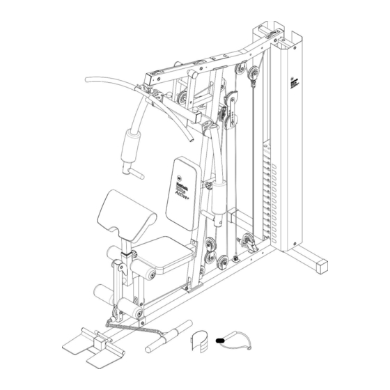
Men's Health Home Gym
Assembly & User Instructions -
–
Important
Please read these instructions fully before assembly or use
These instructions contain important information which will help you get the best from your
equipment and ensure safe and correct assembly, use and maintenance.
If you need help or have damaged or missing parts, call the Customer Helpline:
http://www.argoshelpdesk.co.uk
Please keep for future reference
241/4742
0345 604 0105
Issue 1 -4/29/14
Advertisement
Table of Contents

Related Manuals for Argos 241/4742


Summary of Contents for Argos 241/4742
- Page 1 Men’s Health Home Gym 241/4742 Assembly & User Instructions - Please keep for future reference – Important Please read these instructions fully before assembly or use These instructions contain important information which will help you get the best from your equipment and ensure safe and correct assembly, use and maintenance.
-
Page 2: Table Of Contents
Contents Safety Information Components - Parts Components – Fixings Assembly Instructions 8-23 Free area and training area Exercising Information 25-28 Before starting to exercise Muscle chart Warming up and cooling down 27 -28 Exercises Care and Maintenance Exploded Parts List 30-31 Guarantee... -
Page 3: Safety Information
If you have damaged or missing parts, please MUST read all instructions before using any fitness equipment. Argos assumes no responsibility for Components - Parts call the Customer Helpline: 0345 600 0464. Safety Information personal injury or property damage sustained by or through the use of this product. -
Page 4: Components - Parts
Note: Some of the smaller components may be pre-fitted to larger components. Please check carefully before contacting Argos regarding any missing components. Total mass of the product is 140kg. Foot print of the product is 208cm * 105cm. Rear stabilizer × 1 Base frame ×... - Page 5 Please check you have all parts listed below Note: Some of the smaller components may be pre-fitted to larger components. Please check carefully before contacting Argos regarding any missing components. Lat bar × 1 22&23. L&R Pinch protector × 1 Foot plate Clip hook ×...
- Page 6 Please check you have all parts listed below Note: Some of the smaller components may be pre-fitted to larger components. Please check carefully before contacting Argos regarding any missing components. 94. 15 Joint chain × 1 69. 25 mm End 97mm Pulley ×...
- Page 7 Please check you have all parts listed below Note: Some of the smaller components may be pre-fitted to larger components. Please check carefully before contacting Argos regarding any missing components. 36. 2mm Washer × 2 61. 26mm Bushing × 2 62.
-
Page 8: Components - Fixings
Note: The quantities below are the correct amount to complete the assembly. In some cases more hardware may be supplied than is actually required. Some of the smaller components may be pre-fitted to the larger components. Please check carefully before contacting Argos regarding any missing components. M10 × 170mm Allen bolt × 1 M10 ×... -
Page 9: Assembly Instructions
Assembly instructions Step 1 a. Insert the Guide rods (3) into the holes on the Rear stabilizer (2). Fix using 2 x M10 x 25mm Allen bolts (47) and 2 x 10mm Washers (64). b. Slide 2 x Ø61mm Rubber bumpers (85) down onto Guide rods (3). c. - Page 10 Assembly instructions Step 2 a. Attach the Vertical frame (4) to the Base frame (1). Fix using 2 x M10x 85mm Carriage bolts (53), the 110mm bracket (29),2 x 10mm Washers (64) and 2 x M10 Aircraft nuts (63). b. Insert the Foot Plate Tube (26) into the Foot plate (15) and the holes on the Base frame (1).Then press the 2 x 25mm End cap (69) onto the Foot plate (15).
- Page 11 Assembly instructions Step 3 a. Carefully slide 14 x 10LBS Weight plates (84) down Guide rods (3), insert the Select rod (32) into the Weight plates (84), and then slide 1 x 5LBS Select plate (83) down Guide rods (3). b.
-
Page 12: Upper Frame
Assembly instructions Step 4 a. Attach Upper frame (5) to Guide rods (3) fix using 2 x M10 x 25mm Allen bolts (47) and 2 x 10mm Washers (64). b. Attach Upper frame (5) to the Vertical frame (4), fix using 2 x M10 x 90mm Carriage bolts (51), 110mm Bracket (29), 2 x Ø10mm Washers (64) and 2 x M10 Aircraft nuts (63), Note: (67/72) were fixed in the factory. - Page 13 Assembly instructions Step 5 a. Attach the Front press base (6) to the Upper frame (5) using the M10 x 154mm Axle (55). Secure using 2 x 10mm Washers (64), 2 x M10 x 20mm Allen bolts (48) and 2 x 50mm End caps (82). b.
-
Page 14: Support
Assembly instructions Step 6 a. Attach the Leg developer holder (24) to the Base frame (1), fix using M10 x 85mm Carriage bolt (53), 10mm Washer (64) and M10 Aircraft Nut (63). b. Attach the Seat support (11) to the Vertical frame (4), fix using 2 x M10 x 90mm Carriage bolts (51),90mm Bracket (28), 2 x 10mm Washers (64) and 2 x M10 Aircraft Nuts (63). - Page 15 Assembly instructions Step 7 a. Insert the Backrest adjustment frame (33) into the Vertical frame (4),to find your desired exercising position and fix it with 73mm Lock pin (88). b. Insert the Preacher pad support (12) into the Seat support (11),to find your desired exercising position and fix it with 73mm Lock knob (88).
-
Page 16: Front Press Base
Assembly instructions Step 8 a. Attach the ‘pivots’ on the Right Butterfly’s (8) to the Front press base (6) using Cap nut (59), M6 x 33mm Cheese head bolt (43) and M6 Aircraft nut (58).Fix the 80mm Lock knob (89) to the Right Butterfly frame (10). - Page 17 Assembly instructions Step 9 a. Feed the bolt end of the 3700mm Upper cable (104) up through opening in Upper frame (5). Insert 15mm bushings (65) into holes and attach 1st/2nd/3rd Pulley (70) using M10 x 65mm Allen bolt (44) and M10 Aircraft nut (63).
- Page 18 Assembly instructions Step 10 a. Hook one end of the 3020mm Butterfly cable (105) to Right butterfly (7). Place a Pulley (70) under the cable, position the pulley into the Swivel pulley brackets (18). Fix using M10 x 45mm Allen bolt (50), 2 x 10mm Washers (64) and M10 Aircraft nut (63). b.
- Page 19 Assembly instructions Step 11 a. Attach the Right pinch protector (22) onto the Front press base (6) . Fix using M8 x 18mm Allen bolt (42), 2 x 8mm Washers (57) and M8 Aircraft nut (60). b. Repeat a. to attach the left side.
- Page 20 Assembly instructions Step 12 a. Feed the loop end of the 3750mm Lower cable (106) up through opening in Leg developer (13). Insert 2 x 15mm Sleeves (65) into holes and attach 1st Pulley (70) using M10 x 65mm Allen bolt (44) and M10 Aircraft nut (63).
- Page 21 Assembly instructions 1520 Step 13 a. Fix the end of the 1520mm cable (107) to the Floating pulley bracket (30) using M10 x 30mm Allen bolt (54), 2 x 10mm Washers (64) and M10 Aircraft nut (63). b. Place Pulley (70) onto the cable and the pulley bracket as diagram show, using M10 x 50mm Allen bolt (49), 2 x 10mm Washers (64), Flap (34) and M10 Aircraft nut (63).
-
Page 22: Seat Support
Assembly instructions Step 14 a. Attach the Preacher pad (37) to the Preacher pad stand (12). Secure using 2 x M8 x 18mm Allen bolts (42) and 2 x 8mm Washers (57). b. Attach the Seat pad (38) to the Seat support (11). Secure using 4 x M8 x 18mm Allen bolts (42) and 4 x 8mm Washers (57). - Page 23 Assembly instructions Step 15 a. Fix the Weight cover (31&102) to the Upper frame (5) and the Rear stabilizer (2), using 2 x M10 x 16mm Allen bolts (40), 2 x 10mm Washers (64). b. Repeat a. to assemble the other side parts.
- Page 24 Assembly instructions Step 16 Important: Now fully tighten the fixings ensuring that all of the pulleys and brackets can move freely. a. Attach the Lat bar (20) onto the Upper frame (5) hooks. b. Connect the Single handle (97) or Ankle strap (98) or Pull bar (103) to the end of 3750mm Lower cable (106) using 2 x Clip hooks (95) and 15 Joint chain (94).
-
Page 25: Free Area And Training Area
Free area and training area The free area should be no less than 0.6m greater than the training area in the directions from which the equipment is accessed. The free area must also include the area for emergency dismount. Where equipment is positioned adjacent to each other the value of the free area may be shared. -
Page 26: Exercising Information
Exercising Information Before starting to exercise Before starting to exercise How you begin your exercise programme depends on your physical condition. If you have been inactive for several years or are severely overweight, you must start slowly and increase a few minutes per workout. Initially, you may be able to exercise only for a few minutes in your target zone;... -
Page 27: Muscle Chart
Exercising Information Muscle chart Aerobic Exercise Aerobic exercise improves the fitness of your lungs and heart - your body’s most important muscle. Aerobic exercise fitness is promoted by any activity that uses your large muscles (arms, legs or buttocks, for example). Your heart beats quickly and you breathe deeply. -
Page 28: Warming Up And Cooling Down Exercises
Exercising Information Warming up and Cooling down exercises Each workout should include the following three parts: 1. A warm up, consisting of 5 to 10 minutes of stretching and light exercise. A proper warm up increases your body temperature, heart rate and circulation in preparation for exercise. 2. - Page 29 Exercising Information Calf / Achilles stretch With one leg in front of the other, reach forward and place your hands against a wall. Keep your back leg straight and your back foot flat on the floor. Bend your front leg, lean forward and move your hips toward the wall.
-
Page 30: Care And Maintenance
Care and Maintenance with assembly, operation or Examine the equipment Inspect and tighten all parts use of your exercise product periodically in order to detect before using the equipment. or if you think that you may any damage or wear which Replace defective have parts missing, contact may have been produced. -
Page 31: Exploded Parts List
Exploded Parts List Part Description Qty. Part Description Qty. Base frame Floating pulley bracket Rear stabilizer Left weight stack cover Guide rod Select rod Vertical frame Backrest adjustment frame Upper frame Flap Front press base M8 x 23mm Allen bolt Left butterfly 2mm Washer Right butterfly... -
Page 32: Joint Chain
110mm Bracket M6 Aircraft nut Exploded Parts List Cap nut 10LB Weight plate M8 Aircraft nut Rubber bumper 26mm Bushing Select pin Pipe sleeve 10mm Bushing M10 Aircraft nut 73mm Lock knob 10mm Washer 80mm Lock knob 15mm Sleeve 6mm Washer 18mm Bushing Big Foam 28mm Bushing... -
Page 33: Guarantee
• The guarantee is in addition to, and does not diminish your statutory or legal right. • In the event of problem with the product with in the guarantee period call Customer Helpline: 0345 604 0105 http://www.argoshelpdesk.co.uk Guarantor: Argos Ltd 489 – 499 Avebury Boulevard Central Milton Keynes MK9 2NW...
Need help?
Do you have a question about the 241/4742 and is the answer not in the manual?
Questions and answers