Table of Contents
Advertisement
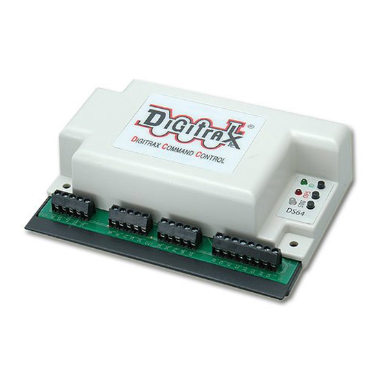
Stationary Decoder for use with 4
slow motion, solenoid, or bi-polar
turnout machines
F F e e a a t t u u r r e e s s
Simple to hook up and configure
n
Control 4 individual turnout machines, EITHER
n
4 Slow motion turnout machines, such as Tortoise
Switchmaster
TM
OR
4 Solenoid-type turnout machines such as three wire (twin coil type) Peco or
Atlas Snap Switches or two wire bi-polar type turnout machines such as Kato
Unitrack, AristoCraft, or LGB turnouts with capacitive discharge capability
Support for up to 8 routes
n
Screw terminals make installation easy
n
Use with any LocoNet Compatible System
n
DCC compatible for non-LocoNet Use
n
FCC Class B compliant
n
I I n n t t r r o o d d u u c c t t i i o o n n
The DS64 is a state of the art stationary decoder that can control multiple types
of turnout machines and other stationary accessory motors and lighting. The
DS64 accepts commands from LocoNet Compatible Command Stations &
Throttles (via LocoNet), DCC Command Stations & Throttles (via the rails), a
computer (via LocoNet), or via eight manual inputs. Each output can handle up
to two devices simultaneously.
©2007 Digitrax, Inc
D D
C C
i i g g i i t t r r a a x x
o o m m p p l l e e t t e e
R R u u n n Y Y o o u u r r T T r r a a i i n n s s , , N N o o t t Y Y o o u u r r T T r r a a c c k k ! !
www.digitrax.com
T T
C C
r r a a i i n n
o o n n t t r r o o l l
Track Voltage Up to 22 Volts
TM
by Circuitron or
All Scales
1
Advertisement
Table of Contents

Related Manuals for Digitrax DS64


Summary of Contents for Digitrax DS64
- Page 1 I I n n t t r r o o d d u u c c t t i i o o n n The DS64 is a state of the art stationary decoder that can control multiple types of turnout machines and other stationary accessory motors and lighting. The DS64 accepts commands from LocoNet Compatible Command Stations &...
- Page 2 Q Q u u i i c c k k S S t t a a r r t t Your DS64, as shipped from the factory, is set up for solenoid or bi- polar turnout operation. Three wire (twin coil type) Peco...
- Page 3 NOTE: If your DS64 is powered by an auxiliary power supply, the static output voltage for use with slow motion turnouts will be 12 volts. If your DS64 is powered by the track (TRKA & TRKB), then the static output voltage will be equal to the track voltage.
- Page 4 Figure 1: DS64 Diagram DS64 Control Panel Buttons STAT is used for setting up routes and for setting the DS64 board ID for use with the DS64’s Inputs. OPS is used for setting up how the DS64 works (for setting Option Switches).
- Page 5 DS64 at this time. 2. On the DS64 press and hold the OPS button down for about 3 seconds until the red OPS LED and green ID LED begin to blink alternately. This indi- cates that the DS64 is ready to change the option switches.
- Page 6 R R u u n n Y Y o o u u r r T T r r a a i i n n s s , , N N o o t t Y Y o o u u r r T T r r a a c c k k ! ! Connecting Your Turnouts to the DS64 Once you have set up your DS64 to operate the type of turnouts you will use, the next step is to hook up the turnouts to the outputs of the DS64. Each type of turnout machine has specific requirements for wiring.
- Page 7 + & - wire connections to achieve correct operation. Note: You cannot ‘mix and match’ outputs. As an example, you cannot use both the slow motion switch machine on the same DS64 as the crossing signal. ©2007 Digitrax, Inc...
- Page 8 R R u u n n Y Y o o u u r r T T r r a a i i n n s s , , N N o o t t Y Y o o u u r r T T r r a a c c k k ! ! DS64 Address Programming Your DS64 has 4 Outputs labeled 1R & 1G, 2R &2G, 3R & 3G, and 4R & 4G, which are shipped from the factory programmed as Switch Addresses 01, 02, 03, and 04 respectively.
- Page 9 @ @ d d i i g g i i t t r r a a x x . . c c o o m m Connecting Input Devices to Your DS64 You can use the 8 inputs on the DS64 to control the operation of the 4 outputs that control your turnouts.
- Page 10 Figure 4: Connecting Input Devices to Your DS64 Using Option Switches to Control Turnouts with Your DS64 The DS64 gives you many options for how you can control the turnouts and other stationary features on your layout. By setting the DS64’s option switches you can configure it for many different possibilities.
- Page 11 1. Begin with your DS64 powered up and connected to the track. Turnouts can be either connected or not. 2. On the DS64 press and hold the OPS button down for about 3 seconds until the red OPS LED and green ID LED begin to blink alternately. This indi- cates that the DS64 is ready to change the option switches The following table shows the factory default settings (Thrown) for the DS64.
- Page 12 Thrown(factory default) at power on, all DS64s and their 4 outputs power up automatically to their last state. Closed at power on, the DS64 powers up and the 4outputs do not power up until they receive a command. Option Switch 07-Reset DS64 To Factory Default Setting ©2007 Digitrax, Inc...
- Page 13 Outputs 1-4 set to Switch Addresses 01-04 respectively. All Routes are erased. Option Switch 08-Startup delay and power management issues OpSw 08 doubles the DS64’s startup delay. The startup delay tells the DS64 to wait for a certain amount of time after the layout is powered up before ‘waking up’.
- Page 14 Closed,the DS64 accepts computer commands only. DCS100 owners - this is also known as the Bushby bit. Option Switch 11-Operate Local Routes Using DS64 Inputs OpSw11 This option is not yet implemented. Do not change. Option Switch 12-Forced Output on High OpSw 12 determines weather the local inputs are set to toggle a turnout from one state to the other or to force the state to closed or to thrown.
- Page 15 Closed disables operation of routes. Option Switches 17-20 Setting Up a Crossing Gate A crossing gate can be set up using a DS64 in slow motion mode (OpSw 01 = Closed). See Figure 3 for hook up diagram. OpSw 17 Thrown (factory default) the Crossing Gate feature is disabled.
- Page 16 Switch command. Route tables hold the Switch Address and position information that make up the Route that operates when a single command is issued. The DS64 has a route table that can hold up to 8 routes and each route can contain up to 8 turnouts.
- Page 17 You are now ready to set up a Route. 2. To program the DS64 Route Number, use your DCC throttle in Switch mode to select a Switch Address from 1 through 8 and issue a Closed or Thrown command.
- Page 18 "thrown" or “closed” command to operate all routes, making it easier to remember which position goes with which route to make them work. Since DS64 routes can only be 8 addresses deep, if you use a "virtual" top address, you will only be able to operate 7 actual turnouts with each route.
- Page 19 Note: If your route includes switch addresses from more than one DS64, they must both be connected to LocoNet or the route will not run. For larger routes, you can set up Cascading Routes by using multiple DS64's as explained in detail in our on-line "DS64 application note".
- Page 20 DS64 Stationary Decoder for use with 4 slow motion solenoid, or bi-polar turnout machines 2443 Transmitter Road Panama City, FL 32404 www.digitrax.com 850-872-9890 850-872-9557 Made In USA sales@digitrax.com ©2008 Digitrax, Inc www.digitrax.com...
Need help?
Do you have a question about the DS64 and is the answer not in the manual?
Questions and answers