Table of Contents
Advertisement
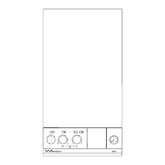
28CDi RSF
WALL MOUNTED COMBINATION BOILER FOR CENTRAL HEATING
AND MAINS FED DOMESTIC HOT WATER
INSTALLATION AND
SERVICING INSTRUCTIONS
To Domestic Hot Water
Minimum
Maximum
28.0 kW
IMPORTANT: THESE INSTRUCTIONS APPLY IN THE UK ONLY
THESE INSTRUCTIONS ARE TO BE LEFT WITH THE USER OR AT THE GAS METER
This appliance must be installed by a competent person in accordance
with the Gas Safety (Installation and Use) Regulations 1994
Bosch Group
GC NUMBER 47 311 34 (N.G.)
GC NUMBER 47 311 35 (L.P.G.)
BOILER OUTPUT
Automatic Modulating Control
To Central Heating
9.0 kW
9.0 kW
24.0 kW
Advertisement
Table of Contents

Related Manuals for Worcester 28CDi RSF


Summary of Contents for Worcester 28CDi RSF
-
Page 1: Servicing Instructions
Bosch Group 28CDi RSF WALL MOUNTED COMBINATION BOILER FOR CENTRAL HEATING AND MAINS FED DOMESTIC HOT WATER INSTALLATION AND SERVICING INSTRUCTIONS GC NUMBER 47 311 34 (N.G.) GC NUMBER 47 311 35 (L.P.G.) BOILER OUTPUT Automatic Modulating Control To Domestic Hot Water... -
Page 2: Table Of Contents
British Standards in addition to those mentioned in the instructions. 1.5 The advice and instructions given in this document covers, as far as possible, the foreseeable situations which may arise. Contact Central Worcester Heat Systems for advice on specific installations. heating Water by-pass diverting adjustment 2. - Page 3 Extension flue lengths available are from 651mm to 3000mm. individual outlets. For further information contact Worcester A terminal guard, Type K2, GC 393 553, is available from Tower Heat Systems Ltd.
-
Page 4: Technical Data
The data plate is fixed to the inner casing cover. Check data plate 3. Technical Data to ensure appliance has been adjusted for supply gas. Table 1 NOMINAL BOILER RATINGS (10 Minutes After Lighting) BOILER ADJUSTED FOR G20 (Natural Gas) BURNER SETTING OUTPUT INPUT... -
Page 5: Siting The Appliance
Notwithstanding the instructions given in BS 5440:2, this 4. Siting The Appliance appliance may be fitted in a compartment with no vents as long as the minimum clearances stated in Section 6: Air Supply, are maintained. 4.1 The appliance may be installed in any room although particular attention is drawn to the requirements of the current 4.7 The airing space must be separated from the boiler space by I.E.E. -
Page 6: Siting The Flue Terminal
5. Siting The Flue Terminal 6. Air Supply See Fig. 4 6.1 The appliance does not require a separate vent for combustion air. 5.1 The flue must be installed as specified in BS 5440:Part 1. 6.2 The appliance can be fitted in a cupboard with no vents for cooling but the minimum clearances must be increased to those 5.2 The terminal must not cause an obstruction nor the given below. -
Page 7: Sealed Primary Systems
fitted as shown). 7. Sealed Primary Systems Insert the bayonet end of the filling key into the corresponding cut outs in the filling loop housing and twist to lock the key in place. See Figs. 5, 6 and 6a. Turn the grey knob anti-clockwise to allow water ingress and fill 7.1 The system must comply with the requirements of BS 6798 until the required pressure is reached. -
Page 8: Open Vent Primary Systems
8.4 A pressure relief valve is not required on an open vented 8. Open Vent Primary Systems system. 8.1 The size of the flow and return pipework is given in Section 3 8.5 Air within the appliance will be expelled via the feed and –... -
Page 9: Electrical
However, if frost protection is necessary for the system, please contact Worcester See Figs. 8, 9, 10, 11, 12 and 13. - Page 10 Fig. 10. Functional flow diagram. Outputs Inputs DHW control knob Electronics/ CH Control knob microprocessor (Safety Low Voltage) CH pressure adjust pot Gas valve mode switch Reset button Convert AC to low voltage electronics Electronics Electronics (2 speed) Pump Electronics...
- Page 11 Fig. 11. 230 V room thermostat connections. Spare Remove link Fig. 12. 230 V programmer connections. Spare Motor Fig. 13. 230 V room thermostat and programmer connections. Spare Motor...
-
Page 12: Installation
Flue components 11. Installation 1. Appliance casing sealing gasket 2. Flue Turret The appliance is supplied suitable for fitting to a sealed system. If 3. Flue Collar it is to be fitted to an open vent system refer to section 8. 4. - Page 13 NOTE: READ THIS SECTION FULLY BEFORE COMMENCING 11.3 AIR AND FLUE DUCT PREPARATION AND ASSEMBLY INSTALLATION Check the contents of the standard flue duct kit against the packing list. Similarly check the extension duct kits if applicable. 11.2 GENERAL FITTING. Remove all the packing from the ducts and terminal assembly.
- Page 14 11.5 INTERNAL FITTING OF THE DUCT ASSEMBLY The rubber sealing gasket and the clamping ring are available from Worcester Heat Systems. Measure and cut the ducts as previously described for external fitting (Section 11.4). Fix the ducts to the terminal and fit the rubber sealing gasket and clamp to the terminal.
- Page 15 Align the flue turret with the 4 holes on the appliance and screw tightened. down. See Fig. 16. If a facia mounted programmer is to be fitted follow instructions Refit the fan. Do not use any sealant on the joint. Replace the with the programmer..
-
Page 16: Commissioning
Check that the pressure relief valve operates by turning the knob anti- 12. Commissioning clockwise until it releases. Water should be expelled from the discharge pipe. See Fig. 24. Lower the control box to gain access. Refer to Section 14.3(c). 12.1 SUMMARY Set the Expansion Vessel Pressure The appliance is dispatched with the controls set to provide a... - Page 17 If the appliance is being passed over to the user immediately, refer to Section 13 – Instructions to the User and set the controls that the supply pressure is sufficient) the correct pressure is not obtained then Worcester Heat Systems Service Department to the users requirements. should be contacted.
-
Page 18: Instructions To The User
Hinge down the facia. 13.4 Tell the user of the importance of regular servicing. Turn the Mode Switch to the “Max.” position. Worcester Heat Systems Ltd. offer a comprehensive maintenance Turn on a hot tap. contract. Wait until the appliance reaches stationary equilibrium 13.5 Set the system controls to the user’s requirements. -
Page 19: Replacement Of Parts
assembly from the appliance. See Fig. 28. When refitting the 15. Replacement Of Parts hood ensure that the rear return edge passes under the lip at the rear of the combustion chamber. (g) Combustion Chamber Front and Sides. Remove the inner 15.1 IMPORTANT casing cover and flue hood assembly. - Page 20 AIR PRESSURE SWITCH damage them. Open the valves and fill and re-pressurise the system as 2. Air Flow Pressure Switch. See Fig. 30. described in Section 12.2. Check that the electricity supply to the appliance is turned off. Remove the cabinet front panel as described in Section 14.3 (a). 8.
- Page 21 13. Central Heating Sensor. See Fig. 31. Remove the Bottom panel, water to water heat exchanger, micro switch assembly and filling loop as described in Section 14.3(d) Remove the inner casing cover as described in Section 14.3(b). and 15. 4 (20) and (24). Check that the electricity supply to the appliance is turned off.
-
Page 22: Short Parts List
Combustion Chamber Insulation Pack WHS 7 716 192 204 0 299 355 Fibre Washer Pack 7 716 192 205 0 299 356 ‘O’ Ring Pack 7 716 192 207 0 299 357 Fuse Pack 7 716 192 206 0 Accessories For 28CDi RSF... -
Page 24: Operational Flow Diagrams
17 Operational Flow Diagrams... -
Page 27: Fault Finding
18. Fault Finding Note: This fault-finding information is for guidance only. Worcester Heat Systems cannot be held responsible for costs incurred by persons not deemed to be competent. The electronic control system for this boiler incorporates four lights on the facia. These are used to show normal operating status. But as a secondary function, by flashing, they can also be used to help provide fault diagnostics. - Page 36 Bosch Group Worcester Heat Systems Limited, Cotswold Way, Warndon, Worcester WR4 9SW. Telephone: (01905) 754624. Fax: (01905) 754619. Technical Helpline (0990) 266241. This booklet is accurate at the date of printing but will be superseded and should be disregarded if specifications and/or appearances are changed in the interests of continued improvement.
Need help?
Do you have a question about the 28CDi RSF and is the answer not in the manual?
Questions and answers