Table of Contents

Related Manuals for EUROSEC CP 8

Summary of Contents for EUROSEC CP 8
-
Page 3: Table Of Contents
Contents Introduction ..... . 2 Mains Safety ....2 Good Working Practice . -
Page 4: Introduction
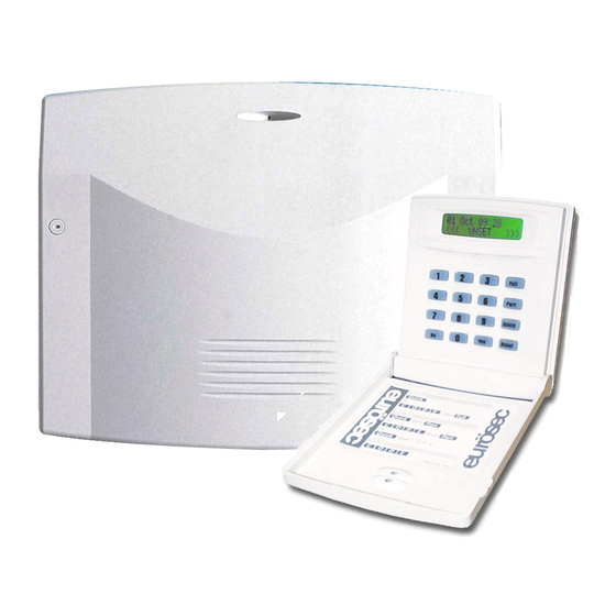
Introduction The eurosec control panel is supplied as a blank fronted end station complete with RKP. Up to 3 additional may be fitted if required. The unit is fully programmable by the installation and comes pre-programmed with a set of factory defaults that will suit most installations. Seven... -
Page 5: Installation
Control Panel & RKP Location Consideration needs to be given to the location of the Control Panel & RKP with regards to- The surface that the unit(s) are to be fixed to should be firm, vibration free, damp free and fire resistant. -
Page 6: Wiring
General Detector Wiring We would strongly suggest that you adopt a colour scheme for the detector wiring of your system. This will enable you to quickly determine the source of any problems that may occur. The security industry does not have recommended colour schemes because of the nature of the wiring, one suggested scheme is given below. -
Page 7: Wiring Passive Infra-Red Detectors
Fig. 2 Wiring Single Contact Fig. 3 Wiring Double Contact (on the same zone) Wiring Passive Infra-Red Detectors It is essential when using Passive Infra-Red Detectors that you refer to the manufacturers instruction as to the positioning and settings of the detector. This section is intended as a guide to the wiring of the detectors. -
Page 8: General Bell Box Wiring
Sample Bell Box Connections Below is shown general and sample bell box connections for some of the popular bell boxes that are available. Fig.6A General bellbox Fig.6B connections eurosec control panel terminals Tamper Feed Novagard Delta eurosec control bellbox connections panel terminals... - Page 9 Fig.6E Fig.6F CQR Integra HS Texecom Azura eurosec control bellbox connections bellbox connections eurosec control panel terminals Common panel terminals (Select AT Return) SAB TMP SAB TMP AT Return Bell Hold - Bell Hold - Supply -VE Bell - Bell -...
-
Page 10: Wiring Notes
Wiring Notes Fig. 7 Control Panel Connections The 680 Ohm resistor (provided) must be fitted across 12v & D1 at the last RKP in line. Maximum current draw from the panel MUST NOT EXCEED 1Amp. This includes all Bells, Sounders, Speakers, Detectors & RKPs etc. Max Output current for Strobe is 250mA Max Output current for Bell is 500mA Panel speaker volume may be adjusted via RV1... -
Page 11: Programming
Terminology Various terms are used throughout this manual that may be unique to the eurosec control panel. This section gives brief details of this terminology. Zones 12Hr Alert A zone programmed as 12Hr is active when Internal Speaker only. the system is set. -
Page 12: Engineer Programming Mode
Engineer Programming Mode Two programming modes are available to the engineer these are Engineer/User Mode and Engineer Programming Mode. This section will deal with the Engineer Programming Mode covering options 11 to 30. The function of the LEDs within this mode are to indicate the numbers 0 to 9 as shown in Fig. 9. -
Page 13: Programmable Engineer Options
Programmable Engineer Options & & & & Each zone may have a type (first digit) and attribute (second digit) programmed by the engineer. Zone 1 is programmed through Option 11, Zone 2 through Option 12 and so on until Zone 7 through Option 17 (or Zone 8 for CP8 through Option 18) First Digit Second Digit Default Settings (Zones) - Page 14 & & & & Part Set Sounders (first digit) refer to the internal speaker mode during Part Sets. PGM1 (second digit) refers to PGM1 Terminal on control panel PCB. First Digit Second Digit Default Settings = 31 0 = All Part Sets Silent 0 = Pulse On 3 = All Part Sets Audible 1 = Part Set 2 Silent...
- Page 15 Bell Re-Arms is the number of times the bell will Re-Arm after an alarm. If this option is set to 99 the number of Re-Arms is infinite. Range may be 00 to 99 (Re-Arms) Default = 99 Re-Arms Bell Ring Time is the time in minutes that the bell will ring when an alarm is triggered. The default is 20 minutes but you should check local bylaws for any restrictions in your area.
-
Page 16: Engineer/User Mode
Engineer/User Mode The engineer has a second mode available via the engineer code. This Engineer/User mode allows the engineer to operate the system as a user. For details of user functions including setting and unsetting the system please refer to the user manual. Options available are:- Remove Zone (Menu No. -
Page 17: Engineer Reset
It should be noted that if the new engineer code starts with a 9 it will be locked into the system. Defaulting the panel will not return the engineer code to the factory default. It may only be changed by accessing it through this engineer code. To program the engineer code proceed as follows. -
Page 18: Resetting To Factory Defaults
Resetting to Factory Defaults If required the unit may be reset to factory defaults. It should be noted that if the engineer code begins with a 9 it will not be defaulted. Remove all power from the system. Wait 10 seconds. Re-Apply power to the system. -
Page 19: Troubleshooting
Fault Action Control Panel will not power up from the Check / Replace fuse in fused spur or mains mains supply connection block. Also check all connections for trapped insulation. Display shows zone fault and panel will not Remove zone wires from the problem zone at set after the exit time has expired. - Page 20 Fault Action Tamper is not tripped when a detector cover is Check to see if all tampers are wired in series. removed. If detector tampers have been wired in parallel they will all have to be removed before the tamper would trigger. Check for short circuits that may occur through staples piercing cables.
-
Page 21: Specifications
Power Input 230v a.c +/- 10% @50Hz No. of Zones CP7 = 7 CP8 = 8 Max Loop Resistance 2K Ohms Loop Delay Time 300 milliseconds Fuses Mains Fuse 200mA slow blow F2 Misc Fuse 250mA quick blow F1 System Fuse 1A quick blow Low Voltage Output 13.8v (typical) Regulated... -
Page 22: System Details
Customer Name Customer Address Tel No: Fax No: Installation Date Installing Engineer(s) Control Panel Location RKP Location(s) Zone 1 Location Zone 5 Location Zone 2 Location Zone 6 Location Zone 3 Location Zone 7 Location Zone 4 Location Zone 8 Location (CP8 only) Programmed Settings Option No. - Page 24 Supplied By:- Technical Helpline 01706 510200 PR4958 Rev2.0...
Need help?
Do you have a question about the CP 8 and is the answer not in the manual?
Questions and answers