Table of Contents
Advertisement
TABLE OF CONTENTS
1
INTRODUCTION ................................................................................................................ E-2
1.1
Unpacking and inspecting .................................................................................................. E-2
1.2
General notes on use and safety ....................................................................................... E-2
1.3
Electromagnetic compatibility ............................................................................................ E-2
2
DESCRIPTION ................................................................................................................... E-3
2.1
Characteristics and possible applications ......................................................................... E-3
2.2
Construction ....................................................................................................................... E-5
2.3
Principle of operation ......................................................................................................... E-6
2.4
Safety position .................................................................................................................... E-7
2.5
Technical data .................................................................................................................... E-8
3
INSTALLATION ................................................................................................................. E-9
3.1
Construction and assembly ................................................................................................ E-9
3.1.2 Fitting the positioner to a type 2031 continuous valve with piston drive ............... E-11
3.1.3 Fitting the positioner to a continuous valve with rotary drive ................................. E-13
3.2
Fluid ports ......................................................................................................................... E-14
3.3
Electrical connections ...................................................................................................... E-15
4
OPERATION .................................................................................................................... E-16
4.1
Controls and indicators .................................................................................................... E-16
4.2
Operating levels ............................................................................................................... E-17
4.3
Setting up ......................................................................................................................... E-18
4.4
Process control ................................................................................................................. E-19
4.4.1 Meaning of LEDs and keys in the process control level ........................................ E-20
4.4.2 Displays ................................................................................................................... E-20
4.5
Configuration .................................................................................................................... E-21
4.5.1 Additional functions ................................................................................................. E-21
4.5.2 Configuration menu ................................................................................................. E-22
4.5.3 Function of keys in the configuration level ............................................................. E-25
4.5.4 Notes on the basic and additional functions .......................................................... E-25
4.6
Manual operation without power supply .......................................................................... E-34
4.7
Structure of the positioner ................................................................................................ E-35
5
MAINTENANCE ............................................................................................................... E-36
Fault messages ................................................................................................................ E-36
APPENDIX ....................................................................................................................... E-37
A1: Characteristics of PID controllers .............................................................................. E-37
A2: Rules for adjusting PID controllers ............................................................................ E-39
A3: Optional board for analog position indication ............................................................ E-44
A4: Optional board for binary position indication/Booster ............................................... E-45
1067
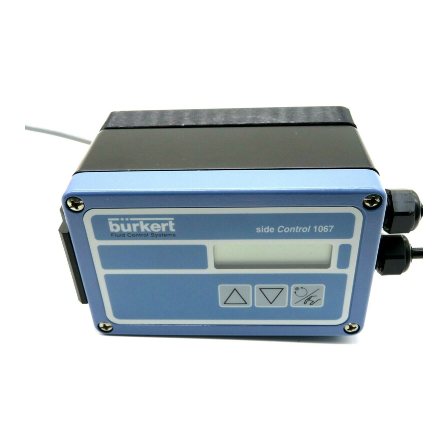
POSITIONER TYPE 1067
E-1-
Advertisement
Table of Contents

Subscribe to Our Youtube Channel
Related Manuals for Burkert 1067


Summary of Contents for Burkert 1067
-
Page 1: Table Of Contents
TABLE OF CONTENTS POSITIONER TYPE 1067 INTRODUCTION ........................ E-2 Unpacking and inspecting ....................E-2 General notes on use and safety ..................E-2 Electromagnetic compatibility .................... E-2 DESCRIPTION ........................E-3 Characteristics and possible applications ................. E-3 Construction ........................E-5 Principle of operation ......................E-6 Safety position ........................ -
Page 2: Introduction
We congratulate you on the purchase of our positioner. positioner type 1067. You have made a good choice. To be able to make the best use of the Repairs may only be carried out by authorised many advantages the product has to offer, it is trained personnel. -
Page 3: Description
If an error exists, the electropneumatic system causes the actual position to be appropriately corrected. The type 1067 positioner can be fitted to various continuous valves (e.g. valves with piston, membrane or rotary drives and with single or double action). Two variant forms of the basic device are offered that differ in their fixing options and feedback/positional transducers. - Page 4 2 DESCRIPTION POSITIONER TYPE 1067 Fig. 1 Block diagram of the type 1067 positioner Position controller with additional functions, e. g. - close tight function - plug travel limitation - setting speed limitation - split range - correction characteristics - deadband...
-
Page 5: Construction
2 DESCRIPTION POSITIONER TYPE 1067 2.2 Construction The positioner consists of the following main assemblies: - Body and bonnet (aluminium) - internal feedback/positional transducer for measuring valve position - Microprocessor/electronic unit for signal processing and control - Solenoid valves for control of a continuous action valve... -
Page 6: Principle Of Operation
POSITIONER TYPE 1067 2 DESCRIPTION 2.3 Principle of operation Fig. 4 shows a operational diagram of the positioner with its relationship to a piston drive control valve. An external feedback/positional transducer is used in this case to measure the actual position. -
Page 7: Safety Position
2 DESCRIPTION POSITIONER TYPE 1067 Fig. 5 Position control Setposition PWM element Position controller Valve actuator Fig. 6 Process control Valve actuator Process Position controller PWM-element Process position controller Auxiliary control loop Main control loop 2.4 Safety position In the event of power failure, the functioning of the actuator ensures that a pre-determined end position is adopted (opened or closed by spring pressure). -
Page 8: Technical Data
2 DESCRIPTION POSITIONER TYPE 1067 2.5 Technical data Electrical data Power supply: 24 VDC Power consumption: < 10 W Input for desired value Input for setpoint for position or process control: - Unit signal 4 ... 20 mA - Unit signal 0 ... -
Page 9: Installation
POSITIONER TYPE 1067 3.1 Construction and assembly The type 1067 positioner can be fitted to various continuous valves. Depending on the valve type either variant 1, with an internal feedback/positional transducer (a rotary potentiometer) or variant 2, with an external feedback/positional transducer (a linear potentiometer) is used (see section 2.3). - Page 10 3 INSTALLATION POSITIONER TYPE 1067 Fig. 9 Position of lever during assembly Parallel Set positioner, with the mounting elbow screwed on to it, on the membrane drive so that the pin slots into the carrier , the point of the lever runs parallel with the upper edge of the positioner (Fig.
-
Page 11: Fitting The Positioner To A Type 2031 Continuous Valve With Piston Drive
3 INSTALLATION POSITIONER TYPE 1067 3.1.2 Fitting the positioner to a type 2031 continuous valve with piston drive Arrangement In the case of a continuous valve with piston drive, variant 2 with the external path-measuring system (Fig. 3) should be used. The positioner is placed on the valve and screwed to it (Figs. 11 and 12). The valve position is transmitted directly via the spring-mounted rod of the path-measuring system (the linear potentiometer). - Page 12 3 INSTALLATION POSITIONER TYPE 1067 Set path-measuring system directly on the drive from above. Great care must be taken to ensure that the spindle of the path-measuring system is seated on the spindle of the drive. Screw in the path-measuring system and secure with spanner.
-
Page 13: Fitting The Positioner To A Continuous Valve With Rotary Drive
3 INSTALLATION POSITIONER TYPE 1067 3.1.3 Fitting the positioner to a continuous valve with rotary drive Arrangement In the case of a continuous valve with rotary or part-turn valve actuating drive, variant 1 with an internal feedback/positional transducer should be used. Its shaft is coupled to the valve rotary drive (e.g. -
Page 14: Fluid Ports
3 INSTALLATION POSITIONER TYPE 1067 Fig. 17 Coupling for continuous valve with Fig. 18 Assembly of positioner on to a rotary drive continuous valve with rotary drive Continuous valve with rotary drive 3.2 Fluid ports Connect P port with compressed air supply (6 bar max.) -
Page 15: Electrical Connections
3 INSTALLATION POSITIONER TYPE 1067 3.3 Electrical connections Fig. 20 Assignment of terminals Signal input: - either for valve position control - or for process regulation control Input for process regulation Binary input Contact Output (Option) Power Supply Input U1 (unit signal 0 ... 10 V): Input resistance 200 kΩ... -
Page 16: Operation
4 OPERATION POSITIONER TYPE 1067 4.1 Controls and indicators AUTOTUNE „Arrow up“ key MANUAL/AUTOMATIC key „Arrow down“ key 4.2 Operating levels 2 operating levels are provided for operation of the positioner: ° Process operation level This level, which is automatically set each time the unit is switched on, allows to change over between the MANUAL and AUTOMATIC operating modes. -
Page 17: Setting Up
4 OPERATION POSITIONER TYPE 1067 4.3 Setting up The following basic settings are to be carried out on the initial setting up (commissioning) of the positioner in conjunction with the 2632 angle-seat control valves (specification of basic functions): - Specification of the positional feedback of the continuous valve to the positional transducer (direct or lever), - Specification of the unit signal input chosen for entering the set position (0 ... - Page 18 4 OPERATION POSITIONER TYPE 1067 To perform a setting within the X-SENS and INPUT menu items, briefly press the MANUAL/ AUTOMATIC key again. One of the menu sub-items then appears in the display. It is possible to switch back and forwards between these sub-items, each of which describes a possible setting, by again pressing the arrow keys.
-
Page 19: Configuration Menu
4 OPERATION POSITIONER TYPE 1067 To leave the main menu for the settings during the setting up, first select the END menu item by pressing the arrow keys. Then press the MANUAL/AUTOMATIC key to restore the unit to the operating mode which was present before the changeover to the main menu (MANUAL or AUTOMATIC). - Page 20 4 OPERATION POSITIONER TYPE 1067 Displays in the MANUAL mode Process controller inactive The actual position of the actuator is displayed: XPOS___ (0...100%) Process controller active In the HAND operating condition no operations are being carried out, the actual value of the process quantity is continuously displayed: PV____ (-99.9...999.9).
- Page 21 4 OPERATION POSITIONER TYPE 1067 4.5 Configuration 4.5.1 Additional functions The operating concept of the positioner is based on a strict separation between basic and additional functions. Only the basic functions are activated in the delivery state of the unit. These enable the unit-specific basic settings to be carried out on the initial setting up (cf §...
- Page 22 4 OPERATION POSITIONER TYPE 1067 X-LIMIT Limitation of mechanical range - XMIN - Input of initial value of stroke range in %. - XMAX - Input of final value of stroke range in % X-TIME Limitation of correcting time - OPN FAST...
- Page 23 4 OPERATION POSITIONER TYPE 1067 4.5.2 Configuration menu The configuration menu can be activated from the process control level by pressing the MANUAL/ AUTOMATIC key during 5 seconds. It consists of a main menu and additional menu. The main menu contains mainly the basic functions which are to be specified on the initial setting up (cf §...
- Page 24 4 OPERATION POSITIONER TYPE 1067 Fig. 26 Complete configuration menu X-SENS DIRECT LEVER 4...20MA INPUT 0...20MA 0...10V ACTUATE SINGLE INTERN BOOST DOUBLE CHARACT LINEAR 1/25 1/50 25/1 50/1 FREE DEADBND CLTIGHT DIRECTN WPOS RISE FALL XPOS RISE FALL SPLTRNG X-MAX...
-
Page 25: Function Of Keys In The Configuration Level
4 OPERATION POSITIONER TYPE 1067 4.5.3 Function of keys in the configuration level Operation of the „Arrow up“ key - Scroll upwards in menu (selection). - Incrementing numerical values in a selected and confirmed menu item. Operation of the „Arrow down“ key - Scrolling downwards in the menu (selection). - Page 26 4 OPERATION POSITIONER TYPE 1067 ACTUATE (factory setting: SINGLE, INTERN): Method of operation of the valve actuator used. Options: SINGLE, INTERN: Use of a single acting actuator with intern or without boost valves, SINGLE, BOOST: Use of a single acting actuator with boost valves,...
- Page 27 4 OPERATION POSITIONER TYPE 1067 Input of the freely-programmable characteristic curve The characteristic curve is defined by means of 21 restart points distributed uniformly over the set positioning range of 0 ... 100%. These are spaced at 5%. A freely-selectable stroke (range 0 ... 100%) can be assigned to each restart (Fig.
- Page 28 4 OPERATION POSITIONER TYPE 1067 Fig. 28 Example of a characteristic curve to be programmed Plug travel (%) Unit signal (%) Set position (%) Plug travel (%) Input with "Arrow" keys Restart point E-28- 1067...
- Page 29 4 OPERATION POSITIONER TYPE 1067 DEADBND (factory setting : DBD = 0.5%): Deadband around the system deviation The DEADBND additional function enables the response of the actuator to occur only after a specific system deviation [DBD] (Fig. 29). This „protects“ the servo valve.
- Page 30 4 OPERATION POSITIONER TYPE 1067 DIRECTN (FACTORY SETTING: WPOS = RISE, XPOS = RISE): Sense or direction of action. By means of the WPOS additional function the sense of action between the input signal and the setpoint (WPOS). can be set, and also by means of XPOS the assignment of the air supply state of the actuator A1 to the indicated value (XPOS).
- Page 31 4 OPERATION POSITIONER TYPE 1067 X-LIMIT (factory setting: XMIN = 0%, XMAX = 100%): Stroke limitation. This additional function enables the (physical) stroke to be limited to a given MIN and MAX percentage value (Fig. 33). In the AUTOMATIC mode the stroke range of the limited stroke is then set to equal 100%.
- Page 32 4 OPERATION POSITIONER TYPE 1067 TV: (rate time) Range of settings: 0.0...999.9 (factory setting: 0) X0: (Operating point of process controller) Range of settings: 0...100% (factory setting: 0%) DBD: No sensibility range of the process controller Range of settings: 0,2...5% (factory setting: 0,5 %) SCALE: Scales the inputs of the process controller.
- Page 33 4 OPERATION POSITIONER TYPE 1067 BIN-IN (factory setting: INACTIVE): Binary input. The action of the binary input (contact) can be specified by means of this additional function. Options: INACTIVE: Binary input is not active. SAFEPOS (safety position): Input of a safety position SPOS selected if necessary.
-
Page 34: Manual Operation Without Power Supply
4 OPERATION POSITIONER TYPE 1067 4.6 Manual operation without power supply The solenoid valves integrated in the positioner can be manually operated without a power supply by using rotary knobs. These rotary knobs (red) are accessible when the bonnet of the unit is opened. -
Page 35: Structure Of The Positioner
4 OPERATION POSITIONER TYPE 1067 4.7 Structure of the positioner Fig. 36 Flowchart of positioner type 1067 E-35- 1067... -
Page 36: Maintenance
5 MAINTENANCE POSITIONER TYPE 1067 Fault messages Faults during switch on Message Possible cause Remedy INT.ERROR Internal fault Not possible, unit defective Fault messages during AUTOTUNE function Message Possible cause Remedy TURN POT Range of the position transducer exceeded Remove the positioner from (only with internal feedback transducer option) the actuator,and turn the transducer from 180°. -
Page 37: Appendix
APPENDIX POSITIONER TYPE 1067 A1: Characteristics of PID controllers A PID controller has a proportional, an integral and a differential component (P, I and D components). P component : Function : Y = Kp • Xd Kp is the proportional action coefficient. It results from the ratio of the manipulating range ∆Y to the proportional range ∆Xd. - Page 38 APPENDIX POSITIONER TYPE 1067 Ymax Ymin Control range Manipulating time Characteristic Step response Characteristics : A pure I controller eliminates the effects of occuring disturbances completely. Therefore, it has a favorable static response. Owing to its finite manipulating speed, it operates more slowly than the P controller and tends to oscillate.
- Page 39 APPENDIX POSITIONER TYPE 1067 Supperposition of P-, I- and D components: d Xd Y = Kp Xd + ƒ Xd dt + Kd Where Kp•Ti = Tn and = Tv, results with regard to functioning of the PID controller: d Xd Y = Kp (Xd + ƒ...
- Page 40 APPENDIX POSITIONER TYPE 1067 Realised PID controller D component with delay : In the positioner type 1067, the D component is realised with a delay T. Function : + Y = Kd Step response Supperposition of P-, I- and DT components :...
-
Page 41: A2: Rules For Adjusting Pid Controllers
APPENDIX POSITIONER TYPE 1067 A2: Rules for adjusting PID controllers The litterature on control systems specifies a series of adjustment rules with which a favorable adjustment of controller parameters can be achieved experimentally. To avoid bad adjustments, the conditions under which the respective adjustment rules have been elaborated must always be observed. - Page 42 APPENDIX POSITIONER TYPE 1067 On the basis of Kcrit and Tcrit, the controller parameters can then be calculated in accordance with the following table: Parameter settings according to Ziegler und Nichols : Controller type Parameter settings P controller Kp = 0,5 Kcrit...
- Page 43 APPENDIX POSITIONER TYPE 1067 The following table lists the settings for the controller parameters depending on Tu, Tg and Ks for command and disturbance response and for an aperiodic control operation as well as a control operation with 20% overshoot. They apply to systems with a P response, with a dead time and with a delay of the 1st order.
- Page 44 APPENDIX POSITIONER TYPE 1067 A3 : OPTION BOARD "4-20 mA ANALOG POSITION INDICATION" (IDENT. 427193G): MOUNTING AND CONNECTION The positioner must be equipped with the software version F, or higher. Check it in the main menu, option END: it is displayed at the right-hand side of the screen.
- Page 45 APPENDIX POSITIONER TYPE 1067 A4 : OPTION BOARD "BINARY POSITION INDICATION/BOOSTER": MOUNTING AND CONNECTION - The positioner must be equipped with the software version F, or higher. Check it in the main menu, option END: it is displayed at the right-hand side of the screen.
- Page 46 APPENDIX POSITIONER TYPE 1067 Connection 1) As potential free contacts connect the cables to the O5 and O6 or O7 and O8 terminals according to the connection schematic place the jumper on the "REL" position (see figure below) GND3 GND4...
- Page 47 POSITIONER TYPE 1067 E-47- 1067...
- Page 48 POSITIONER TYPE 1067 E-48- 1067...
- Page 49 SERVICE Australia Bürkert Contromatic Niederlassung München Burkert Fluid Control Systems China/HK Ltd. Paul-Gerhardt-Allee 24 Unit 1 No.2, Welder Road Beijing Office D-81245 München Seven Hills NSW 2147 Rm. 808, Jing Tai Building Tel +49 89 82 92 28-0 Tel +61 2 967 461 66 No.
- Page 50 Alpha Contromatic Co. Ltd. 259/13 Sukhmvit 22 Malaysia Singapore Bangkok 10110 Bürkert Malaysia Sdn. Bhd. Burkert Contromatic Singapore Tel +420 641 22 61 80 N° 22 Lorong Helang 2 Pte.Ltd. Fax +420 641 22 61 81 11700, Sunggai Dua No.11 Playfair Road...
Need help?
Do you have a question about the 1067 and is the answer not in the manual?
Questions and answers