Table of Contents
Advertisement
Quick Links
Download this manual
See also:
Technical Manual
Advertisement
Table of Contents

Related Manuals for GE MDS SD4 Series


Summary of Contents for GE MDS SD4 Series
- Page 1 ™ MDS SD4 Software-Controlled Digital Communications Firmware Release 1.x.x MDS 05-4669A01, Rev. A December 2007...
- Page 2 A power connector with screw-type retaining screws as supplied by GE MDS must be used. Do not disconnect equipment unless power has been switched off or the area is known to be non-hazardous.
-
Page 3: Front Panel Layout
INTRODUCTION This guide presents basic installation and operating instructions for the MDS SD4 Series wireless transceiver. It is a companion guide to the MDS SD4 Series Reference Manual (Part No. 05-4670A01). Refer to the Reference Manual for additional details and system design infor- mation. -
Page 4: Standard Accessories
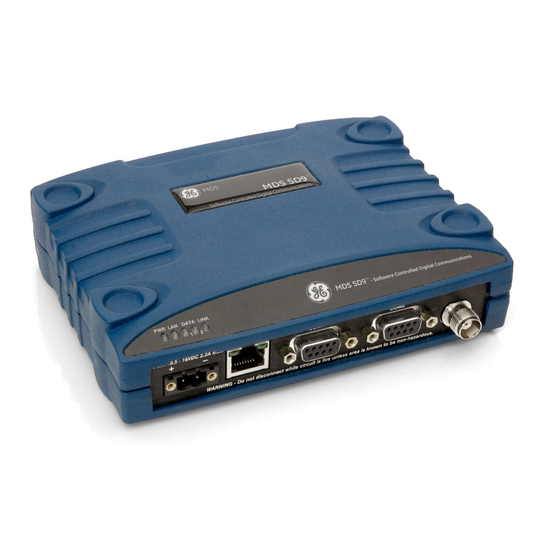
Invisible place holder Figure 2. Front Panel Connectors & Indicators Connector functions (left to right) are as follows: • POWER • (RJ-45) • Management/Diagnostics (DB-9) COM1— • Payload Data (DB-9) COM2— • (TNC) ANTENNA LED functions are described in Table 3 on Page Standard Accessories Table 1 lists accessories normally shipped with the transceiver. -
Page 5: Installation
Table 1. Accessories Supplied with the Unit Accessory Description Part Number DC Power Plug, Mates with power connector on radio. 73-1194A39 2-pin, polarized Screw terminals provided for wires, threaded locking screws to prevent accidental disconnect. Radio PC software used for setting the basic 03-3156A01 Configuration operating parameters of the radio. -
Page 6: Installation Steps
ANTENNA SYSTEM TRANSCEIVER POWER SUPPLY 10.5–16 VDC @ 2A Negative Ground Only DATA TELEMETRY DEVICE Figure 3. Typical Remote Station Arrangement Installation Steps Below are the basic steps for installing the transceiver. In most cases, these steps alone are sufficient to complete the installation. Refer to the Reference Manual for additional information. - Page 7 Invisible place holder 7.25˝ (16.99 cm) Figure 4. Transceiver Mounting Bracket Dimensions CAUTION Using screws longer than 1/4 inch (6 mm) may damage the POSSIBLE unit’s internal PC board. EQUIPMENT DAMAGE 2. Install the antenna and feedline for the station. Aim directional antennas toward the master station.
- Page 8 Invisible place holder Lead Binding Screws (2) Retaining Screws (2) Wire Ports (2) (Polarity: Left +, Right –) Figure 5. DC Power Connector CAUTION The transceiver must be used with negative-ground sys- tems only. The power supply used with the transceiver POSSIBLE should be equipped with overload protection (NEC EQUIPMENT...
- Page 9 b. Set the transmit frequency by entering , where TX xxx.xxxx is the frequency in MHz. Press xxx.xxxx ENTER response indicates successful entry. PROGRAMMED OK c. Set the receive frequency by entering , where RX xxx.xxxx is the frequency in MHz. Press xxx.xxxx ENTER response...
-
Page 10: Troubleshooting
Table 2. Command Summary (Cont’d) Command Name Function OWM [XXX...] Set or display the owner’s message. OWN [XXX...] Set or display the owner’s name. PORT [RS232, RS485] Selects signaling standard to be used on DATA port. PWR [20–37] Set or display the transmit power setting. RSSI Display the Received Signal Strength Indication. -
Page 11: Led Indicators
• The correct interface between the transceiver and the connected data equipment (correct cable wiring, proper data format, tim- ing, etc.) LED Indicators The LED status indicators (Figure 7) are an important troubleshooting tool and should be checked whenever a problem is suspected. Table 3 describes the function of each status LED on the top panel of the radio. -
Page 12: Event Codes
Event Codes When an alarm condition exists, the transceiver creates a code that can be read on a connected terminal. These codes can be helpful in resolving many system difficulties. Refer to Table 4 (Page 11) for a definition of the event codes. Checking for Alarms—STAT command To check for alarms, connect a terminal to the radio’s (diagnos-... -
Page 13: Event Code Definitions
The codes shown are a subset of a larger pool of codes used for various GE MDS products. For this reason, the table does not show a sequential listing of all code numbers. Only the codes appli- cable to this product are shown. - Page 14 The spectrum analyzer display is accessed by entering spectrum xxx.xx at the command prompt, where the characters denote the center frequency and span frequency, respectively. The frequencies are entered in megahertz. For example, a sample entry would be spectrum , corresponding to a center operating frequency of 410.00 410.00 1.5 MHz and a span (sweep width) of 1.5 MHz.
-
Page 15: Com2 Connections
Invisible place holder > DB-9 MALE DB-9 FEMALE < (RADIO SIDE) (COMPUTER) Figure 9. COM1 Wiring to Computer COM2 CONNECTIONS The COM2 connector (Figure 10) is used to connect the radio to an external DTE telemetry device that supports the EIA/RS-232 or EIA/RS-485 (balanced) format, depending on how the radio is config- ured. - Page 16 Table 5. COM2 Pin Descriptions—RS/EIA-232 (Cont’d) Input/ Number Output Pin Description Signal Ground— Connects to ground (negative supply potential) on chassis. Alarm Output (DSR)—An RS-232 high/space (+5.0 Vdc) on this pin indicates an alarm condition. An RS-232 low/mark (–5.0 Vdc) indicates normal operation. This pin may be used as an alarm output.
-
Page 17: Specifications
Invisible place holder 4-WIRE CONNECTIONS 2-WIRE CONNECTIONS TXD + RXD + TXD + RXD+/TXD+ RXD + RXD – RXD + RXD – TXD + RXD – RXD–/TXD– TXD – TXD – TXD – Figure 11. EIA-422/485 Wiring Schemes (Left: EIA-422, Right: EIA-485) SPECIFICATIONS GENERAL Frequency Range*:... -
Page 18: Primary Power
PRIMARY POWER Voltage: 13.8 Vdc Nominal (10.5 to 16 Vdc) Negative-Ground Systems Only TX Supply Current: 2.0 Amperes (Maximum) @ 5 Watts RF Output RX Supply Current: Operational—125 mA, Nominal Fuse: 4-Amp Thermal Fuse, Self-Resetting, Internal (Remove primary power to reset) ENVIRONMENTAL Humidity: 95% at 40 degrees C (104°F),... - Page 20 GE MDS, LLC 175 Science Parkway Rochester, NY 14620 General Business: +1 585 242-9600 FAX: +1 585 242-9620 Web: www.GEmds.com...