Table of Contents
Advertisement
READ THIS MANUAL
PLEASE KEEP FOR PERMANENT REFERENCE
This manual covers the preliminary installation, operation and general
maintenance requirements for Aquafine Ultraviolet Water Treatment
Equipment for the following applications:
• Disinfection
• Ozone Destruction
• TOC Reduction
SL Series
It is imperative that those responsible for the installation of this equipment,
as well as operating personnel, read this manual and carefully follow all
instructions and guidelines. EQUIPMENT OPERATORS AND INSTALLERS
MUST COMPLY WITH OPERATIONAL SAFETY REQUIREMENTS.
Aquafine Corporation builds the finest quality ultraviolet equipment in the
world. When properly installed and operated, Aquafine ultraviolet
treatment units will provide many years of service.
Part No. 108-1, Revised 10/03
Installation,
Maintenance and
Operation Manual
Advertisement
Table of Contents

Summary of Contents for Aquafine MP-2-SL
- Page 1 EQUIPMENT OPERATORS AND INSTALLERS MUST COMPLY WITH OPERATIONAL SAFETY REQUIREMENTS. Aquafine Corporation builds the finest quality ultraviolet equipment in the world. When properly installed and operated, Aquafine ultraviolet treatment units will provide many years of service.
-
Page 3: Table Of Contents
Installation and Operational Safety ....3 Description of Equipment SL Series ............4 Treatment Chamber ..........4 Warranty Information ........4-5 Refer to this nameplate decal on your unit when ordering parts or service. Unit Installation Where to Install the Unit ........6 How to Protect Your Unit ........ -
Page 4: Installation And Operational Safety
safety requirements for UV equipment The following safety requirements relate directly to operator safety. Please review with all appropriate personnel to ensure continuous compliance. These safety requirements are This “Safety Issue” icon marks M A N DATO RY. all items relating to safety issues. -
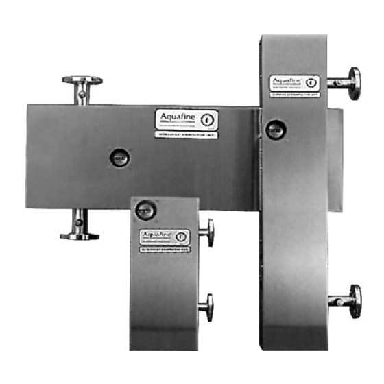
Page 5: Sl Series
Each treatment chamber is fitted with two raised-face This unit mounts vertically. Inside the cabinet housing stainless steel flanges (in the case of the MP-2-SL, each are the ballast and the UV treatment chamber. The chamber has one flange each). The bottom flange is... - Page 6 WARRANTY Aquafine equipment is guaranteed to be free from defects in materials and workmanship (excluding ultraviolet lamps) for a period of one year from the date of purchase. Any part suspected of being defective should be returned prepaid to Aquafine Corporation.
-
Page 7: Where To Install The Unit
where to install the unit operating pressure Install the UV treatment unit in a horizontal position Standard units are rated for a maximum operating in a sheltered area with ample ventilation. Ambient pressure of 120 psig (8.24 bar). temperatures surrounding the unit should be between If your unit has the High Pressure Modification option F (2 C) and 110... -
Page 8: Special Requirements For Ultrapure Water
UV treatment chamber prior to the connection of any nonmetallic materials. UV light traps protect nonmetallic piping. Should you require any additional assistance, please contact your local Aquafine represen- tative or the factory directly. wiring the unit ” conduit knockout ( ”... -
Page 9: Plumbing Requirement
plumbing schematic for Service clearance required on this end. all SL series ultraviolet treatment units RUNNING TIME METER LED UV LAMP OPERATIONAL DISPLAY PANEL Model SL-10A MOUNTING BRACKET PLACES... -
Page 10: Installing The Quartz Sleeves
quartz sleeve installation Over tightening The quartz sleeves designed for this unit are open can break the on both ends. For first time unit installations, follow quartz sleeves or create leaks. these quartz sleeve installation procedures: 1. Turn off all power to the unit. 2. -
Page 11: Installing The Uv Lamps
installing the UV lamps CAUTION! Prior to energiz- ing the ballasts and lamps, Once is has been verified that there are no leaks in the ensure there is no water system, the UV lamps are ready for installation. leaking into the quartz sleeves and compression nut 1. -
Page 12: Powering Up The Ultraviolet (Uv) Unit
Additional service logs are corresponding LED will automatically turn “off”. available from Aquafine, and are intended to be placed on top of the existing service logs. Each UV lamp is numbered at the end of the UV treatment chamber, and the corresponding LED light carries the same number on the display panel;... -
Page 13: S-254 Uv Optical Sensor
more model S-254 UV optical sensor 8. Using a flat screwdriver, adjust the R8L alarm potentiometer until the red LED barely comes on. The optional S-254 UV optical sensor measures the 9. Using a flat screwdriver, set the R3L sensitivity relative output of ultraviolet potentiometer back to 100%. -
Page 14: Ma Sensor Signal Option
The cutoff temperature has been preset at the factory. Should you require a different set point, please contact option Aquafine for assistance. This option works with the optional S-254 optical lamp out alert indicator sensor. It generates a 4-20 mA output signal based upon... -
Page 15: Troubleshooting
using the LED display If an LED bulb does not light after you replace a UV lamp, you need to verify the electrical output of the ballast connected to that specific UV lamp. This is done by testing the ballast open circuit voltage. This should be done by an electrician or qualified facilities personnel. -
Page 16: Maintenance Requirements
& replacement The exterior surfaces of the Aquafine UV unit should be kept clean as part of routine maintenance. Use a soft As water passes through the ultraviolet treatment unit, cloth with soap and water or any commercial stainless minerals, debris and other substances in the water will steel cleaner. -
Page 17: Cleaning The Sensor Probe Window
Periodic sample collection and testing should be to do so may result in false readings. scheduled as often as the user deems sufficient to be assured the quality of the Aquafine ultraviolet unit 6. Replace the probe and the coaxial cable. effluent is acceptable. - Page 18 more found that virtually all removable debris which may We have provided ” NPT threaded fittings on both accumulate within a sample valve can be mechanically the intake and discharge UV chamber flange risers. We flushed during the procedures detailed above. recommend you use these fittings to collect “before and after UV”...
-
Page 19: Parts List
Lamp Socket ........................16184 Running Time Meter - 120 Volt ..................15843 Running Time Meter - 240 Volt ..................15844 COMMON TO ALL SL-1 & MP-2-SL APPLICATIONS Quartz Sleeve ......................... 3184 Ballast (SL-1) - 120 Volt ....................4035 Ballast (SL-1) - 240 Volt ....................3493 Ballast (MP-2-SL) - 120 Volt ..................16518... - Page 20 general part description ........part number SL-10A -- ALL APPLICATIONS Standard UV Lamps DE 254 nm Mauve Disinfection and/or Ozone Destruction Application Size: 15” Length ......................3050 Validated UV Lamps DE 254 nm Green Disinfection and/or Ozone Destruction Applications Size: 15” Length ......................16714 Standard UV Lamps DE 185 nm Blue TOC Reduction Applications Size: 15”...
Need help?
Do you have a question about the MP-2-SL and is the answer not in the manual?
Questions and answers