Advertisement
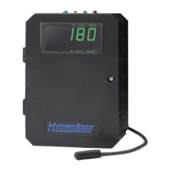
MODEL 3150
Combination Low Water
Cut-Off & Universal
Temperature Limit Control
for Oil-Fired Boilers
120 VAC Operating Voltage
PATENT NOS. 7,891,572; 8,931,708
Dual Function
Design
Temperature Limit Control
Designed for cold start and tankless
coil boilers.
Low Water Cut-Off
Provides protection against potentially
dangerous low water conditions
when installed with the Hydrolevel
Electro-Well™ (see page 2 for details).
WARNING
Electrical shock hazard. To prevent electrical shock, death or
equipment damage, disconnect power supply before
installing or servicing control. Only qualified personnel may install or service this control in
accordance with local codes and ordinances. Read instructions completely before proceeding.
WARNING
Frozen pipes/water damage. Central heating systems are prone to shut down as a result of power or fuel outages,
safety related fault conditions or equipment failure. Installation of freeze protection monitoring or other precautions
is recommended for unattended dwellings in climates subject to sustain below-freezing temperatures.
126 Bailey Road, North Haven, CT 06473 • Phone (203) 776-0473 • FAX (203) 764-1711 •
INSTALLATION INSTRUCTIONS
and OPERATING MANUAL
• Replaces Common Aquastat
*
Models – Can be installed on existing immersion
wells to replace both cold-start and triple-action Aquastats
designations make change-outs quick and easy.
• Digital Display – Easy to read LED continually displays boiler temperature. Also displays
temperature limit and differential settings during adjustment.
• Easy to Set – Dials for setting temperature limits and differentials eliminate complicated
programming.
• Thermal Pre-Purge Feature – Conserves fuel and meets 2012 DOE regulations by
circulating latent heat in the boiler to the heating zone before firing the burner.
•
*Aquastat is a registered trademark of Honeywell International, Inc.
®
. Industry standard wiring
CAUTION
To prevent serious
burns, boiler
should be thoroughly cooled before installing or
servicing control.
www.hydrolevel.com
Advertisement
Table of Contents

Summary of Contents for HydroStat 3150
-
Page 1: Installation Instructions
INSTALLATION INSTRUCTIONS and OPERATING MANUAL MODEL 3150 • Replaces Common Aquastat Models – Can be installed on existing immersion Combination Low Water wells to replace both cold-start and triple-action Aquastats ® . Industry standard wiring Cut-Off & Universal designations make change-outs quick and easy. -
Page 2: Immersion Wells
CORRECT INCORRECT NOTE: In the case of space restrictions, the Fuel Smart HydroStat control may be mounted in a horizontal orientation without any loss of function. Hydrolevel recommends vertical mounting, when possible, for proper orientation of LED display. REMOTE MOUNTING KITS are available separately for mounting the Fuel Smart HydroStat control box in a remote location. - Page 3 WIRING WARNING Electrical shock hazard. To prevent electrical shock, death or equipment damage, disconnect power supply before installing or servicing this control. STEP 1 STEP 2 STEP 3 Connect 120 VAC Hot to Connect the circulator to Connect the burner cir- terminal L1.
-
Page 4: Setting The Control
SETTING THE CONTROL To set COLD START operation Diagnostic LEDs Operates on call for heat only. Test/Settings Button Low Temperature Limit Dynamic Make sure Low Temperature Limit is turned fully Display Water Temperature counter-clockwise (OFF position). Jumper and Real Time Verification of Low Temperature Differential Setting Adjustments. -
Page 5: Optional Features
Manual Reset Low Water Cut-Off The low water cut-off operation on the HydroStat can be set to operate in automatic (default) or manual reset mode. When in manual reset mode, the control will shut-down the burner immediately when a low water condition is detected. If the low water condition is sustained for 30 seconds, the low water light will blink, indicating that the control has locked out the burner. - Page 6 ONLY be available when installed on a standard well. The Hydrostat sensor checks to determine if a standard well is used by looking for low resistance to ground, a condition that can only exist with a standard well. If you are installing on a standard well and either Low Water LED’s are on, setting will not be available.
- Page 7 Indicates that the low water cut-off To View Current Settings: Press and release the (LWCO) function of the HydroStat control is active. When the Test/Settings Button in short intervals to sequentially display control is installed with a Hydrolevel Electro-Well, this LED the following settings: will be on at all times when the control is powered.
-
Page 8: Troubleshooting
If the boiler has a tankless coil make sure the low limit setting on the HydroStat is set properly. NOTE: If the low limit setting is dialed fully counter clockwise, it will shut off the low temperature maintenance feature and will function as a cold start control. - Page 9 Low Temperature Limit to maintain temperature. Is There The Control HydroStat is supplying 120 VAC to the burner circuit. 120 VAC is Operating Between B1 Recheck wiring and operation of burner and other limit controls. Properly.
- Page 10 Is the Check temperature display. When the Low Limit is Low Limit Dial set, the HydroStat will fire the burner until the Set to OFF? temperature reaches the Low Limit Setting. When there is no call to fire the burner, the voltage...
- Page 11 HydroStat installed with Electro-Well™ When installed with the Hydrolevel Electro-Well, HydroStat will provide both temperature and low water cut-off functionality. If the control was supplied by the boiler manufacturer, it was installed with an Electro- Well. The Electro-Well is available separately for field installations.
-
Page 12: Maintenance
REMOTE MOUNTING KITS Part No. Description Part No. Description 48-101 HydroStat Remote Mount Kit with 24" sensor 48-103 HydroStat Remote Mount Kit with 10' sensor 48-102 HydroStat Remote Mount Kit with 48" sensor 48-104 HydroStat Remote Mount Kit with 20' sensor 48-121 HydroStat Pipe Mounting Kit with 48"...
Need help?
Do you have a question about the 3150 and is the answer not in the manual?
Questions and answers