Emerson Rosemount 751 Quick Start Manual
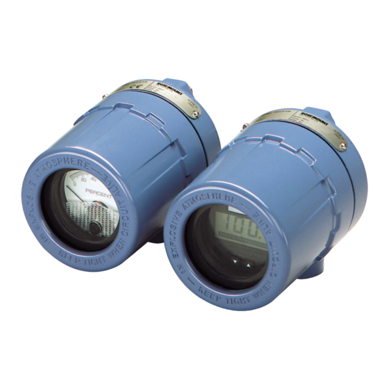
Field signal indicator
Hide thumbs
Also See for Rosemount 751:
- Quick start manual (28 pages) ,
- Reference manual (18 pages) ,
- Reference manual (16 pages)

Related Manuals for Emerson Rosemount 751


Summary of Contents for Emerson Rosemount 751
- Page 1 Quick Start Guide 00825-0100-4378, Rev AD June 2016 ™ Rosemount 751 Field Signal Indicator...
- Page 2 June 2016 Quick Start Guide This guide provides basic guidelines for Rosemount 751 Remote Indicator. It does not provide instructions for configuration, diagnostics, maintenance, service, troubleshooting, Explosionproof, Flameproof, or intrinsically safe (I.S.) installations. Refer to the Rosemount 751 Reference Manual (document number 00809-0100-4378) for more instruction. This manual is also available electronically on www.rosemount.com.
-
Page 3: Installation
June 2016 Installation Assembly The Rosemount 751 Field Signal Indicator is comprised of the components shown Figure 1. The housing may contain an analog or LCD display meter. Both meters are independent of component parts and are completely interchangeable. Both... - Page 4 June 2016 Quick Start Guide Figure 2. Meter Exploded View A. Retaining straps B. Mounting screw into housing C. Washer for retaining strap D. Mounting screws into mounting plate E. Terminal screws (2) F. Mounting plate G. Spacer plate H. LCD display I.
-
Page 5: Wiring Diagrams
4-20 mA transmitter does not contain a test terminal. The Rosemount 751 is designed so the analog or LCD display meter can be removed from the housing without impacting the integrity of the 4-20 mA loop. Removal of the entire Rosemount 751 device from the series configuration will disrupt the loop. - Page 6 June 2016 Quick Start Guide Figure 3. Rosemount 751 Series Wiring Diagrams Rosemount 3144P Temperature Transmitters and Rosemount 2051, 3051C, or 3051S Pressure Transmitters – – 3144P 2051 – – – – 4–20 dc Input Signal for 4–20 mA dc Input Signal for...
- Page 7 Quick Start Guide June 2016 It is recommended that the Rosemount 751 indicator be wired in a parallel configuration when the 4-20 mA transmitter includes a test terminal. Utilization of the test terminal is required in a parallel configuration. Connecting the 751 indicator across the positive and negative terminals of the 4-20 mA transmitter could impact the loop.
- Page 8 June 2016 Quick Start Guide Figure 4. Rosemount 751 Parallel Wiring Diagrams Parallel Wiring Diagrams for Rosemount 3144P Temperature Transmitter and Rosemount 2051, 3051C or 3051S Pressure Transmitters – – 3144P 2051 – – – – 4–20 dc Input Signal for 4–20 mA dc Input Signal for...
-
Page 9: Lcd Display Configuration
Quick Start Guide June 2016 Configuration LCD display configuration The 20-segment bar graph is factory calibrated and represents 4–20 mA directly, but the end points of the LCD display are user-definable. The meter requires a current between 4 and 20 mA in order to be scaled, but the actual value of the current is not significant. -
Page 10: Store The Information
June 2016 Quick Start Guide Table 1. LCD Display Mode Options Options Relationship between input signal and digital display L in Linear LinF Linear with five-second filter Square root SrtF Square root with five-second filter Square root function only relates to the digital display. The bar graph output remains linear with the current signal. -
Page 11: Product Certifications
Quick Start Guide June 2016 Product Certifications European Directive Information A copy of the EC Declaration of Conformity can be found at the end of the Quick Start Guide. The most recent revision of the EC Declaration of Conformity can be found at www.EmersonProcess.com. - Page 12 June 2016 Quick Start Guide Canada E6 Canada Explosionproof Certificate: 1718395 Standards: CSA Std C22.2 No. 25-1966; CSA Std C22.2 No. 30-M1986; CAN/CSA-C22.2 No. 94-M91; CSA Std C22.2 No. 142-M1987 Markings: Explosionproof for CL I, DIV 1, GP C, D; CL II, DIV 1, GP E, F, G; CL III; DIV 1; CL I DIV 2, GP A, B, C, D;...
- Page 13 Quick Start Guide June 2016 I7 IECEx Intrinsic Safety Certificate: IECEx BAS 11.0064X Standards: IEC 60079-0: 2011; IEC 60079-11: 2011 Markings: Ex ia IIC T5/T6 Ga; T6(-60 °C ≤ T ≤ +40 °C), T5(-60 °C ≤ T ≤ +80 °C) Special Condition for Safe Use (X): 1.
- Page 14 June 2016 Quick Start Guide GB3836.16-2006 “Electrical apparatus for explosive gas atmospheres Part 16: Inspection and maintenance of electrical installation (other than mines).” GB50257-1996 “Code for construction and acceptance of electric device for explosion atmospheres and fire hazard electrical equipment installation engineering.”...
- Page 15 Quick Start Guide June 2016 Figure 5. Rosemount 751 Declaration of Conformity...
- Page 16 June 2016 Quick Start Guide...
- Page 18 June 2016 Quick Start Guide China RoHS Rosemount 751 List of Rosemount 751 Parts with China RoHS Concentration above MCVs Hazardous Substances Hexavalent Polybrominated Polybrominated Part Name Lead Mercury Cadmium Chromium biphenyls diphenyl ethers (Pb) (Hg) (Cd) (Cr +6) (PBB)
- Page 19 Quick Start Guide June 2016...
- Page 20 Standard Terms and Conditions of Sale can be found at: www.Emerson.com/en-us/pages/Terms-of-Use.aspx Emerson Process Management The Emerson logo is a trademark and service mark of Emerson Electric Co. Emerson FZE P.O. Box 17033, Rosemount and Rosemount logotype are trademarks of Emerson Process Jebel Ali Free Zone - South 2 Management.
Need help?
Do you have a question about the Rosemount 751 and is the answer not in the manual?
Questions and answers