Table of Contents
Advertisement
Advertisement
Table of Contents

Related Manuals for Microhard Systems BulletPlus


Summary of Contents for Microhard Systems BulletPlus
- Page 1 Operating Manual BulletPlus 4G/LTE Dual SIM Ethernet/Serial/USB Gateway w/WIFI Document: BulletPlus.Operating Manual.v1.3.1.pdf FW: v1.3.0 Build 1014 June 2016 150 Country Hills Landing NW Calgary, Alberta Canada T3K 5P3 Phone: (403) 248-0028 Fax: (403) 248-2762 www.microhardcorp.com...
- Page 2 Important User Information Warranty Microhard Systems Inc. warrants that each product will be free of defects in material and workmanship for a period of one (1) year for its products. The warranty commences on the date the product is shipped by Micro- hard Systems Inc.
-
Page 3: About This Manual
Highlights a key feature, point, or step which is noteworthy. Keeping these in mind will simplify or enhance device usage. An idea or suggestion to improve efficiency or enhance usefulness. Information Information regarding a particular technology or concept. © Microhard Systems Inc. - Page 4 Please Note: These are only sample labels; different products contain different identifiers. The actual identifiers should be seen on your devices if applicable. S'il vous plaît noter: Ce sont des exemples d'étiquettes seulement; différents produits contiennent des identifiants différents. Les identifiants réels devrait être vu sur vos périphériques le cas échéant. © Microhard Systems Inc.
- Page 5 Les adaptateurs muraux fournis avec les émetteurs-récepteurs sont PAS classe 1, division 2 ont approuvé , et par conséquent, doit être alimenté pour les unités à l'aide des connecteurs de type vis ou verrouillage fournies par Microhard Systems Inc. et une Division 2 source d'alimentation de classe 1 au sein de votre panneau .
-
Page 6: Revision History
Dec 2015 Webfilter, MultiWAN, GRE. Misc updates to screenshots & formatting. Updated to firmware v1.3.0-r1012. Misc corrections, added VRRP, Apr 2016 updated Data Usage, Carrier Settings. Updated to firmware v1.3.0-r1014. May 2016 1.3.1 Misc. correcstions. June 2016 © Microhard Systems Inc. -
Page 7: Table Of Contents
3.0 Hardware Features ..................17 3.1 BulletPlus ........................17 3.1.1 BulletPlus Mechanical Drawings ................18 3.1.2 BulletPlus Mounting Bracket (Optional) ..............19 3.1.2 BulletPlus Connectors & Indicators ..............20 3.1.2.1 Front & Top ................... 20 3.1.2.2 Rear & Side ................... 21 4.0 Configuration.................... - Page 8 TCP Client ...................... 114 TCP Server ..................... 114 TCP Client/Server ................... 115 UDP Point-to-Point ..................115 SMTP Client ....................115 PPP ........................ 116 GPS Transparent Mode .................. 117 4.9 I/O ..........................118 4.9.1 Settings ....................... 118 © Microhard Systems Inc.
- Page 9 Appendix C: Port Forwarding Example .................. 215 Appendix D: VPN (Site to Site) Example ................217 Appendix E: Firewall Rules Example ..................219 Appendix F: Port Forwarding w/IP-Passthrough (Iperf) ............221 Appendix G: Troubleshooting ....................223 © Microhard Systems Inc.
-
Page 10: Overview
4G/LTE connections with blazing fast speeds. Providing reliable Cellular Ethernet bridge functionality as well gateway service for most equipment types which employ an RS232, RJ45 or WiFi interface, the BulletPlus can be used in a limitless types of applications such as: ... -
Page 11: Specifications
USB*: USB 2.0 (*Future) USB Console Port USB to Serial Data Routing USB to Ethernet Data Routing (NDIS) Current Consumption: (@12VDC) Model AVG (mA) w/WiFi (AP) BulletPlus BulletPlus + Serial Data BulletPlus + Ethernet BulletPlus Peak © Microhard Systems Inc. - Page 12 Supply voltage 1.5V to 3.05V Current consumption - Typical 20mA (100mA max) Cellular Power Antenna Rejection + Isolation: 824 - 915 MHz > 10dB 1710 - 1785 MHz > 19dB 1850 - 1980 MHz > 23dB © Microhard Systems Inc.
-
Page 13: Quick Start
Installing the SIM Card Before the BulletPlus can be used on a cellular network a valid SIM Card for your Wire- less Carrier must be installed. Insert the SIM Card into the slot as shown, the bottom SIM slot is for SIM1: (The contacts should face down, and the notch to the right) - Page 14 2.0 Quick Start Connect A PC configured for DHCP directly to a LAN port of the BulletPlus, using an Ethernet Cable. If the PC is configured for DHCP it will automatically acquire a IP Address from the BulletPlus. Open a Browser Window and enter the IP address 192.168.168.1 into the address bar.
- Page 15 Carrier > Settings tab and enter the APN supplied by your carrier in the APN field. Some carriers may also require a Username and Password. Auto APN: The BulletPlus will attempt to detect the carrier based on the SIM card installed and cycle through a list of commonly used APN’s...
- Page 16 Congratulations! Your BulletPlus is successfully connected to your Cellular Carrier. Ensure the default To access devices connected to BulletPlus remotely, one or more of the following must be passwords are changed. configured: IP-Passthrough, Port Forwarding, DMZ. Another option would be to set up a VPN.
-
Page 17: Hardware Features
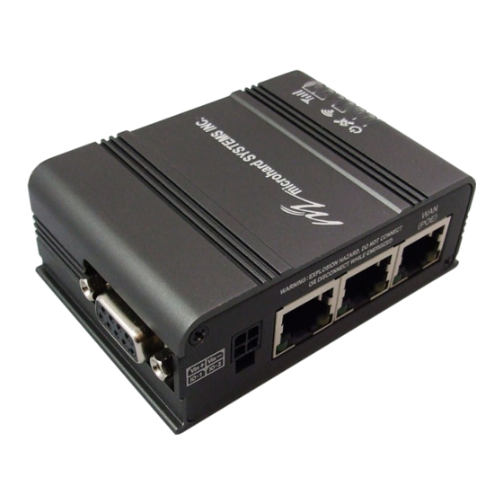
3.1 BulletPlus The BulletPlus is a fully-enclosed unit ready to be interfaced to external devices with standard connectors as discussed below. An optional mounting bracket can be ordered to allow the BulletPlus to be mounted for a fixed installation. Image... -
Page 18: Bulletplus Mechanical Drawings
3.0 Hardware Features 3.1.1 Mechanical Drawings 81.0 17.5 55.2 37.7 12.5 14.5 14.5 14.5 25.0 Drawing 3-1: BulletPlus Top View Dimensions 78.0 13.0 28.0 15.0 81.0 Drawing 3-2: BulletPlus Back View Dimensions 55.2 19.5 28.0 63.2 Drawing 3-3: BulletPlus Side View Dimensions Note: All dimension units: Millimeter ©... -
Page 19: Bulletplus Mounting Bracket (Optional)
3.0 Hardware Features 3.1.2 BulletPlus Mounting Bracket (Order Option) Drawing 3-4: BulletPlus Top View Dimensions (Shown with removable TS35 DIN Rail Mount) 13.0 12.6 16.1 15.2 16.0 12.5 55.2 57.2 32.0 16.8 12.5 16.1 12.6 32.0 58.0 62.4 Drawing 3-5: BulletPlus Mounting Bracket Dimensions Note: All dimension units: Millimeter ©... -
Page 20: Bulletplus Connectors & Indicators
Other SCANNING SCANNING SCANNING SIM card slot. The Bottom slot is SIM1, the contact Table 3-1: RSSI LED’s should face down, and the notch should be to the right. © Microhard Systems Inc. -
Page 21: Rear & Side
On the side of the Bullet is the Data Port (RS232) and on the back are the Power and Ethernet(PoE) interfaces and the 2x Programmable I/O. Drawing 3-7: BulletPlus Rear & Side View The Data Port (RS232 DCE) on the side of the unit is used for... -
Page 22: Configuration
IP Address on your PC to match the default subnet or if your PC is configured for Subnet: 255.255.255.0 DHCP, simply connect a PC to a LAN port of the BulletPlus and it will be assigned a IP address Gateway: 192.168.168.1 automatically. -
Page 23: Logon Window
- particularly once the unit is deployed in the field - for one primary reason: security. If the BulletPlus is restored to factory defaults the password is also restored to the original default password. -
Page 24: System
4.0 Configuration 4.1 System The main category tabs located at the top of the navigation bar separate the configuration of the BulletPlus into different groups based on function. The System Tab contains the following sub menu’s: Summary Status summary of entire radio including network settings, version information, and radio connection status ... -
Page 25: Settings
Port or Telnet) will timeout after becoming inactive. 0-65535 CFG Reset to Default Button Enabled by default, when the CFG button on the front of the BulletPlus Values (Selection) is held down for 10s while the unit is powered up, the unit will reset and all settings will be reset to factory defaults. -
Page 26: Date/Time
Time Settings The BulletPlus can be set to use a local time source, thus keeping time on its own, or it can be configured to synchronize the date and time via a NTP Server. The options and menus available will change depending on the current setting of the Date and Time Setting Mode, as seen below. -
Page 27: Ntp Server Settings
Time The time may be entered in this field. Note that the entered (hh:mm:ss) Values value is lost should the BulletPlus lose power for some reason. 11:27:28 (varies) Timezone (selection) If connecting to a NTP time server, specify the timezone from Values the dropdown list. -
Page 28: Services
4.0 Configuration 4.1.3 System > Services Certain services in the BulletPlus can be disabled or enabled for either security considerations or resource/ power considerations. The Enable/Disable options are applied after a reboot and will take affect after each start up. The Start/Restart/Stop functions only apply to the current session and will not be retained after a power cycle. -
Page 29: Keepalive
Wireless Interface, The CLI (Command Line Interface), The WEBUI, and ensure that they are working as expected. In the event that the BulletPlus does not detect activity on a interface it will reboot to attempt to resolve any issues that may have occurred. - Page 30 The Interval value determines the frequency, or how often, the unit will Values (seconds) send out PING messages to the Host. The BulletPlus will first attempt to re-initialize the cellular model before performing a full system reboot, thus the interval may be delayed by up to 120 seconds)
-
Page 31: Maintenance
This can take several minutes. (no default) Reset to Default The BulletPlus may be set back to factory defaults by using the Reset to Default option under System > Maintenance > Reset to Default. *Caution* - All settings will be lost!!! -
Page 32: Backup & Restore Configurations
Backup & Restore Configuration The configuration of the BulletPlus can be backed up to a file at any time using the Backup Configuration feature. The file can the be restored using the Restore Configuration feature. It is always a good idea to backup any configurations in case of unit replacement. -
Page 33: Reboot
4.0 Configuration 4.1.6 System > Reboot The BulletPlus can be remotely rebooted using the System > Reboot menu. As seen below a button ‘Reboot now’ is provided. Once pressed, the unit immediately reboots and starts its boot up procedure. The BulletPlus can also be restarted on a regular basis by setting up a daily/weekly/monthly schedules. -
Page 34: Network
4.2.1 Network > Summary The Network Summary display gives a overview of the currently configured network interfaces including the Connection Type (Static/DHCP), IP Address, Net Mask, Default Gateway, DNS, and IPv4 Routing Table. Image 4-2-1: Network > Network Status © Microhard Systems Inc. -
Page 35: Lan
LAN Port Configuration The BulletPlus features 2x LAN ports that can be used for connection of devices on a local network. The WAN port can also be bridged with the LAN therefore providing up to 3 LAN ports. By default the has a static IP Address assigned, 192.168.168.1. - Page 36 4.0 Configuration Connection Type This selection determines if the BulletPlus will obtain an IP address Values (selection) from a DHCP server on the attached network, or if a static IP address will be entered. If a Static IP Address is chosen, the fields that follow DHCP must also be populated.
-
Page 37: Lan Dhcp
Ethernet LAN ports, as well as any devices that are connected by WiFi will be assigned an IP by the BulletPlus. The LAN DHCP service is available for each interface, and is located in the add/edit interface menus. - Page 38 (no default) WINS/NBT Node Type Select the method used to resolve computer names to IP addresses. Values (selection) Four name resolution methods are available: B-node: broadcast none P-node: point-to-point b-node M-node: mixed/modified p-node H-node: hybrid m-node h-node © Microhard Systems Inc.
-
Page 39: Vlan Configuration
4.0 Configuration VLAN Configuration The BulletPlus has the capability to add multiple network interfaces, as such it may be desirable to segment these different subnets. The BulletPlus features 802.1Q VLAN. 802.1Q VLAN uses tagging to allow separation of network segments. Ports can belong to multiple VLANs. A Trunk port can be configured to communicate with other VLAN switch by adding all configured VLANs to a single port. -
Page 40: Wan Configuration
4.2.3 Network > WAN WAN Configuration The WAN configuration refers to the wired WAN connection on the BulletPlus. The WAN port can be used to connect the BulletPlus to other networks, the internet and/or other network resources. Image 4-2-6: Network > WAN Configuration Working Mode Use this to set the function of the physical WAN RJ45 port. - Page 41 Select between Manual or Auto for DNS server(s) for the WAN Values (selection) interface. If set to Auto the BulletPlus will try to automatically detect the DNS servers to use, which is normally the case when the WAN is Manual / Auto DHCP.
-
Page 42: Dhcp (Mac Binding)
This section displays the IP Addresses currently assigned through the DCHP service. Also shown is the MAC Address, Name and Expiry time of the lease for reference. The ‘Release All’ button terminates all active leased and requires all connected devices to request new network information (IP/Subnet/etc) © Microhard Systems Inc. -
Page 43: Ddns
Values (Selection) (DDNS), for the BulletPlus. Enable / Disable Network If the BulletPlus is using a wired WAN (ISP) as well as a Cellular Values (Selection) carrier, specific which will use the DNS service. Auto / Carrier / WAN Service This is a list of supported Dynamic DNS service providers. -
Page 44: Routes
Static Routes Configuration It may be desirable to have devices on different subnets to be able to talk to one another. This can be accomplished by specifying a static route, telling the BulletPlus where to send data. Image 4-2-9: Network > Routes... - Page 45 Define the exit interface. Is the destination a device on the LAN, LAN1 Values (Selection) (If physical WAN port is bridged as an independent LAN), 3G/4G (cellular), USB or the WAN? LAN / LAN1 / WAN / Cell / USB None © Microhard Systems Inc.
-
Page 46: Vrrp (Virtual Router Redundancy Protocol)
4.0 Configuration 4.2.7 Network > VRRP The BulletPlus when paired with other VRRP enabled devices (another BulletPlus or compatible devices) can provide redundant internet access for LAN devices by using VRRP (Virtual Router Redundancy Protocol) as illustrated below. If a connected device needs to access the internet it will use whichever virtual router has the highest priority, if that device is not available the next router with the higher priority will router the traffic. -
Page 47: Ports (Switch)
The Network > Ports menu can be used to determine the characteristics of the physical Ethernet interfaces on the BulletPlus. As seen below the Mode (Auto/Manual), Auto-Negotiation, Speed (10/100Mbit/s) and the Duplex (Full/Half) can all be configured on the BulletPlus. -
Page 48: Bandwidth (Throttling Control)
4.0 Configuration 4.2.9 Network > Bandwidth The BulletPlus features Bandwidth Throttling, which allows the upload/download of connected networks/ users data speeds to be limited to a specified value. Network Bandwidth Throttling can be implemented by each physical Ethernet interface as seen in the image below. -
Page 49: Device List
IP address are shown, however not only DHCP assigned devices are listed in the device list, any devices, even those statically assigned, that are connected through the local network interface (RJ45) are displayed, including those connected through a hub or switch. Image 4-2-13: Network > Device List © Microhard Systems Inc. -
Page 50: Cloud Filter (Content/Security Filter)
4.0 Configuration 4.2.11 Network > Cloud Filter The BulletPlus provides Cloud based content filtering and security using the third-party service by Open DNS. OpenDNS is a service which offers free or premium DNS services with added security, phishing protection and optional, advanced content filtering. To get started with OpenDNS an account must first be created with OpenDNS by visiting their website. -
Page 51: Webfilter (Mac/Network Content Filter)
The BulletPlus can provide comprehensive content filtering, limiting access to specific websites and other content. By MAC Address, the BulletPlus allows content to be filtering regardless of the assigned IP address. Filtering can also be applied on a entire network, limiting access to any connected device. - Page 52 Network: Select the local network for which the rule applies. Enabled Domain/URL/IP: See description in MAC Filtering Rules above. Action: See description in MAC Filtering Rules above. Rule Priority: See description in MAC Filtering Rules above. Enabled: Enable or Disable the Network Webfilter rule. © Microhard Systems Inc.
-
Page 53: Multiwan
4.2.13 Network > MultiWAN MultiWAN is used to manage the primary data connection used by the BulletPlus. In cases where a wired WAN (ISP) is available it is generally used for the primary connection as data is usually cheaper (unlimited) than a cellular connection. - Page 54 Generally this will be the cellular connection. WAN / 4G / WIFI Third WAN The WiFi on the BulletPlus can be configured as a client and used as a Values (selection) data connection to access the internet. WAN / 4G / WIFI / Disable...
- Page 55 Values (seconds) from the ICMP Host (when type is configured as ICMP). Attempts Before Failover This is the number of attempts the BulletPlus will attempt to reach the Values (selection) IMCP host before going into failover and switching WAN interfaces.
-
Page 56: Carrier
Not all statistics parameters displayed are applicable. The Received and Transmitted bytes and packets indicate the respective amount of data which has been moved through the radio. The Error counts reflect those having occurred on the wireless link. © Microhard Systems Inc. -
Page 57: Settings
The parameters within the Carrier Configuration menu must be input properly; they are the most basic requirement required by your cellular provider for network connectivity. The BulletPlus can support dual SIM cards, as described below either slot can be specified as the primary slot and if a connectivity issue occurs, the unit can be configured to automatically switch to the alternate SIM card. -
Page 58: Dual Cards Management
The firewall/rules must be configured to allow traffic, all incoming carrier traffic is blocked by default. SIM Selection The BulletPlus supports one or two SIM cards to be installed. By Values (Selection) default the primary SIM is the top SIM, and the unit will try to connect... -
Page 59: Apn
Technologies Mode Select the valid types of Carrier connections allowed. For example if Values (Selection) set to auto the BulletPlus will connect to any data type. If set to WCDMA only, the BulletPlus will only allow connection to WCDMA AUTO... - Page 60 Values (Selection) information to the end device. Enable / Disable SIM Card-2 Settings Settings for SIM Card-2 are identical to that of SIM Card-1, refer to the previous section for information on how to configure SIM Card-2. © Microhard Systems Inc.
-
Page 61: Sms
Image 4-3-3: SMS > SMS Command History 4.3.4 Carrier > SMS Config SMS messages can be used to remotely reboot or trigger events in the BulletPlus. SMS alerts can be set up to get SMS messages based on system events such as Roaming status, RSSI, Ethernet Link Status or IO Status. -
Page 62: Sms Commands
4.0 Configuration Status This option allows a user to enable or disable to use of the following Values (Selection) SMS commands to reboot or trigger events in the BulletPlus: Enable / Disable MSC#REBOOT Reboot system MSC#EURD0 trigger event report0 MSC#NMS Send NMS UDP Report... -
Page 63: Sms Alerts
SMS alerts, when active, will be sent out at the frequency defined Values (Seconds) here. Device Alias The device Alias is text that is sent with the SMS message to provide Values (30 chars) additional information or help identify the source of the SMS alert. UserDevice © Microhard Systems Inc. - Page 64 Disable Roaming Check Enable Roaming Check Home / Roaming Status The BulletPlus can send alerts based on the roaming status. Data Values (Selection) rates during roaming can be expensive and it is important to know when a device has started roaming.
-
Page 65: Data Usage
4.3.5 Carrier > Data Usage The Data Usage tool on the BulletPlus allows users to monitor the amount of cellular data consumed. Since cellular devices are generally billed based on the amount of data used, alerts can be triggered by setting daily and/or monthly limits. - Page 66 Period Start Day For Monthly tracking, select the day the billing/data cycles begins. On this Values (1-31) day each month the BulletPlus will reset the data usage monitor numbers. 1 (Day of Month) Additional Notice 1/2 Up to two (2) additional notices can be sent based on a percentage (10- Values (10-500%) 500%) of the threshold value.
- Page 67 Email account used to send Emails. Most email servers require authentication on outgoing emails. None SSL/TLS STARTTLS SSL/TLS + STARTTLS Mail Recipient Enter the email address of the individual or distribution list to send the Values (xx@xx.xx) email notification to. host@ © Microhard Systems Inc.
-
Page 68: Data Usage History
4.0 Configuration Data Usage History The BulletPlus provides a Odometer that shows the total data used by the BulletPlus. You can also click on the More link to get a data usage history summary as seen below. Image 4-3-11: Data Usage > Data Usage Odometer... -
Page 69: Wireless
Traffic Status shows statistics about the transmitted and received data. The BulletPlus shows information about all Wireless connections in the Connection Info section. The Wireless MAC address, Noise Floor, Signal to Noise ratio (SNR), Signal Strength (RSSI), The transmit and receive Client Connection Quality (CCQ), TX and RX data rates, and a graphical representation of the signal level or quality. -
Page 70: Radio1
On / Off Mode The Mode defines which wireless standard to use for the wireless Values (selection) network. The BulletPlus supports 802.11/b/g/n modes as seen here. Select the appropriate operating mode from the list. 802.11B ONLY 802.11BG The options below are dependant and vary on the operating mode 802.11NG... - Page 71 TX Power This setting establishes the transmit power level which will be Values (selection) presented to the antenna connectors at the rear of the BulletPlus. Unless required, the Tx Power should be set not for maximum, but 11 dBm 21 dBm...
- Page 72 Values (meters) distance the WiFi signal needs to travel. The default is 100m, so the BulletPlus will assume that the signal may need to travel up to 100m so it sets various internal timeouts to account for this travel time.
-
Page 73: Radio Virtual Interface
Wireless Interface, the TX power, Wireless Network information, and Wireless Encryption. The BulletPlus can support multiple virtual interfaces. These interfaces provide different SSID’s for different users, and can also be assigned to separate subnets (Network Interfaces) to prevent groups from interacting. - Page 74 Values (selection) will not be able to communicate with each other. In other words if the BulletPlus is being used as a Hot Spot for many wireless clients, AP On / Off Isolation would provide security for those clients by not allowing access to any other wireless device.
- Page 75 SSID All devices connecting to the BulletPlus in a given network must use Values (string) the SSID of the BulletPlus. This unique network address is not only a security feature for a particular network, but also allows other networks BulletPlus - with their own unique network address - to operate in the same SSID: Service Set Identifier.
-
Page 76: Hotspot
The address of the UAM Server, the authentication portal. https:// customer.hotspotsystem.com/ customer/hotspotlogin.php UAM Secret If the Hotspot Mode, RADIUS/UAM is chosen, this is a secret Values password between the Redirect URL and the Hotspot given by the hotspot provider. hotsys123 © Microhard Systems Inc. - Page 77 Specify the Secondary DNS server to be used by devices connected Values to the Hotspot network. 208.67.222.220 DHCP Start When devices connect to the BulletPlus Wifi and Hotspot is enabled, Values the Hotspot will assign the IP addresses to the connected devices, select the starting range here. DHCP End...
- Page 78 The Radius Account Port Number. The default is 1813. This is Values provided by your Hotspot service provider. 1813 Radius Secret Also called a shared key, this is the RADIUS password assigned by Values you Hotspot provider. hotsys123 © Microhard Systems Inc.
- Page 79 3799 Radius Session Timeout Specify the Radius Session Timeout. In seconds, 0 = disabled. Values (seconds) 3600 Radius Idle Timeout Specify the Radius Idle Timeout. In seconds, 0 = disabled. Values (seconds) © Microhard Systems Inc.
-
Page 80: Firewall
The Firewall Summary allows a user to see detailed information about how the firewall is operating. The All, Filter, Nat, Raw, and Mangle options can be used to view different aspects of the firewall. Image 4-5-1: Firewall > Status © Microhard Systems Inc. -
Page 81: General
WAN Remote Management It is recommended to block all incoming Cellular traffic Allow remote management of the BulletPlus on the WAN side using the Values and create rules to open WebUI on port 80(HTTP), and 443 (HTTPS). If disabled, the configuration specific ports and/or use can only be accessed from the LAN (or Cellular if enabled).. - Page 82 The scrub directive also reassembled fragmented packets, protecting some Enable / Disable operating systems from some forms of attack, and drops TCP packets that have invalid flag combinations. © Microhard Systems Inc.
-
Page 83: Port Forwarding
IP-Passthrough (Carrier > Settings) is another option for passing traffic through the BulletPlus, in this case all traffic is passed to a single device connected to the RJ45 port of the BulletPlus, The device must be set for DHCP, as the BulletPlus assigns the WAN IP to the device, and the modem enters into a transparent mode, routing all traffic to the RJ45 port. - Page 84 Values (selection) DMZ Server IP listed below. Disable / Enable DMZ Server IP Enter the IP address of the device on the LAN side of the BulletPlus where Values (IP Address) all the traffic will be forwarded to. 192.168.100.100 Exception Port...
-
Page 85: Mac-Ip List
MAC List configuration can be used to control which physical LAN devices can access the ports on the BulletPlus, by restricting or allowing connections based on the MAC address. IP List configuration can be used to define who or what can access the BulletPlus, by restricting or allowing connections based on the IP Address/Subnet. - Page 86 Match incoming traffic from the specified source IP range. Boxes accept Values (IP Address) single IP Addresses without network masks, example: 192.168.1.0 to 192.168.1.255 represents all IP Addresses in the 192.168.1.0/24 network. 192.168.0.0 (Put same IP in both boxes for a single IP match.) © Microhard Systems Inc.
-
Page 87: Rules
WAN/Carrier Access Control are configured in the previous menus. Source Select the zone which is to be the source of the data traffic. The LAN/ Values LAN1 refers to local connections on the BulletPlus. LAN/LAN1/WAN/Carrier None © Microhard Systems Inc. - Page 88 Select the zone which is the intended destination of the data traffic. 3G/4G Values (selection) applies to the wireless connection to the cellular carrier and the LAN, LAN1, USB refers to local connections on the BulletPlus. LAN/LAN1/Cell/WAN/USB None Destination IPs Match incoming traffic from the specified destination IP range.
-
Page 89: Firewall Default
4.5.6 Firewall > Firewall Default The Firewall Default option allows a user to return the modems firewall setting back to the default values without having to reset the entire modem. Image 4-4-7: Firewall > Firewall Default © Microhard Systems Inc. -
Page 90: Vpn
The BulletPlus supports VPN IPsec Gateway to Gateway (site-to-site) tunneling, meaning you are using the BulletPlus to create a tunnel to a network with VPN capabilities (Another BulletPlus or VPN capable device). The BulletPlus can also operate as a L2TP Server, allowing users to VPN into the unit from a remote PC, and a L2TP Client. -
Page 91: Gateway To Gateway
A Gateway to Gateway connection is used to create a tunnel between two VPN devices such as an BulletPlus and another device (another BulletPlus or Cisco VPN Router or another vendor…). The local and remote group settings will need to be configured below to mirror those set on the other VPN device. - Page 92 (available such as @microhard.vpn). Enter the server id to use for authentication. The server id can be used only for one tunnel connection. Interface IP Address Displays the IP address of the BulletPlus, which is the local VPN Gateway. Values (IP Address) Current IP Address...
- Page 93 (no default) Subnet IP Address Define the remote network by specifying the local subnet. Values (IP Address) (no default) Subnet Mask Specify the subnet mask of the remote network address. Values (IP Address) 255.255.255.0 © Microhard Systems Inc.
- Page 94 Select value to match the values required by the remote VPN router. Values (selection) modp1024 modp1536 modp2048 Phase 2 Encryption Select value to match the Phase 1 Encryption type used by the remote Values (selection) VPN router. 3des aes128 aes256 © Microhard Systems Inc.
- Page 95 Dead Peer Detection is used to detect if there is a dead peer. Set the DPD Values (seconds) Delay (seconds), as required. DPD Timeout(s) Set the DPD (Dead Peer Detection) Timeout (seconds), as required. Values (seconds) DPD Action Set the DPD action, hold or clear, as required. Values (seconds) Hold Clear © Microhard Systems Inc.
-
Page 96: Client To Gateway (L2Tp Client)
4.0 Configuration 4.6.3 VPN > L2TP Client The BulletPlus can operate as a L2TP Client, allowing a VPN connection to be made with a L2TP Server. Image 4-6-3: VPN > Client to Gateway Tunnel Name Enter a name for the VPN Tunnel. Up to 16 different tunnels can be Values (chars) created, each requiring a unique name. - Page 97 In order to communicate with the devices on the other side of the tunnel, Values (IP Address) the BulletPlus must know which data to pass through the tunnel, to do this enter the Remote Subnet network IP address here. none...
-
Page 98: Openvpn
4.0 Configuration 4.6.4 Network > OpenVPN OpenVPN Server The BulletPlus supports OpenVPN and can be configured as a Server or a Client. This section outlines the configuration of a OpenVPN Server. Image 4-6-4: VPN > OpenVPN Server OpenVPN Mode Enable/Disable the OpenVPN Mode by selecting the mode to operate in, Values (selection) Client or Server. - Page 99 Select between 1024 bit and 2048 bit Diffie Hellman keys for security. Values (selection) DH2048 / DH1024 Server Virtual Subnet / Subnet Mask The subnet and subnet mask that the server will create to assign address Values (IP Address) to itself and the clients. 10.8.0.0 © Microhard Systems Inc.
- Page 100 OpenVPN Server Network Settings OpenVPN support multiple subnet behind server/client. So that the vpn Values (selection) connection can reach the subnet behind. Each subnet must be specified to the data can be routed correctly. (no default) © Microhard Systems Inc.
-
Page 101: Openvpn Client
4.0 Configuration OpenVPN Client The BulletPlus supports OpenVPN and can be configured as a Server or a Client. This section outlines the configuration of a OpenVPN Client. Image 4-6-4: VPN > OpenVPN Celint OpenVPN Mode Enable/Disable the OpenVPN Mode by selecting the mode to operate in, Values (selection) Client or Server. - Page 102 RC2-40-CBC RC2-CBC CAST5-CBC DES-EDE-CBC RC2-64-CBC DES-EDE3-CBC AES-128-CBC DESX-CBC AES-192-CBC BF-CBC AES-256-CBC SEED-CBC Use LZO Compression Enable/Disable LZO compression on the VPN link. Lempel–Ziv– Values (selection) Oberhumer (LZO) is a lossless data compression algorithm. Enable / Disable © Microhard Systems Inc.
-
Page 103: Gre
4.6.4 Network > GRE GRE Configuration The BulletPlus supports GRE (Generic Routing Encapsulation) Tunneling which can encapsulate a wide variety of network layer protocols not supported by traditional VPN. This allows IP packets to travel from one side of a GRE tunnel to the other without being parsed or treated like IP packets. - Page 104 The local setup refers to the local side of the GRE tunnel, as opposed to the remote end. Gateway IP Address This is the WAN IP Address of the BulletPlus, this field should be populated Values (IP Address) with the current WAN IP address.
- Page 105 Values (IP Address) (varies) Remote Setup The remote setup tells the BulletPlus about the remote end, the IP address to create the tunnel to, and the subnet that is accessible on the remote side of the tunnel. Gateway IP Address...
-
Page 106: Vpn Users
Values (characters) (no default) New Password Enter a password for the use. Values (characters) (no default) Confirm New Password BulletPlus Values (IP Address) Enter the password again, the will ensure that the password match. (no default) © Microhard Systems Inc. -
Page 107: Certificate Managment
4.6.6 VPN > Certificate Management When using the VPN features of the BulletPlus, it is possible to select X.509 for the Authentication Type. If that is the case, the BulletPlus must use the required x.509 certificates in order to establish a secure tunnel between other devices. -
Page 108: Router
4.0 Configuration 4.7 Router 4.7.1 Router > RIPV2 The BulletPlus is capable of providing and participating in RIPv2 (Routing Information Protocol v2), to exchange routing information from attached devices. Static routes can also be added in the Network > Routes menu. -
Page 109: Ospf
4.0 Configuration 4.7.2 Router > OSPF The BulletPlus is also capable of providing and participating in OSPF (Open Shortest Path First), to exchange routing information from attached devices. Static routes can also be added in the Network > Routes menu. -
Page 110: Serial
BulletPlus, the port uses a standard DB-9 connector. If USB-to-Serial converters are connected they will also appear as new tabs listed as USB devices. At this time the BulletPlus only supports select devices using generic FTDI or Prolific USB-to-Serial drivers. -
Page 111: Settings
The BulletPlus supports the use of USB-to-Serial converters and new tabs for the USB configuration will appear once a converter has been connected to the USB port of the BulletPlus. At this time only specific generic FTDI and Prolific drivers are supported. -
Page 112: Data Baud Rate
If the attached device does not support hardware handshaking, leave this setting at the default value of ‘None’. When CTS Framing is selected, the BulletPlus uses the CTS signal to gate the output data on the serial port. - Page 113 When enabled the data will continue to buffer received on the serial Values (selection) data port when the radio loses synchronization. When disabled the BulletPlus will disregard any data received on the serial data port when Disable / Enable radio synchronization is lost.
-
Page 114: Ip Protocol Config
Default: 60 (seconds) TCP Server: In this mode, the BulletPlus Series will not INITIATE a session, rather, it will wait for a Client to request a session of it (it’s being the Server—it ‘serves’ a Client). The unit will ‘listen’ on a specific TCP port. -
Page 115: Tcp Client/Server
4.0 Configuration IP Protocol Config (Continued…) TCP Client/Server: In this mode, the BulletPlus will be a combined TCP Client and Server, meaning that it can both initiate and serve TCP connection (session) requests. Refer to the TCP Client and TCP Server descriptions and settings described previously as all information, combined, is applicable to this mode. -
Page 116: Ppp
PPP: COM1 can be configured as a PPP server for a serial connection with a PC or other device. The attached PC could then use a dedicated serial (WindowsXP - dialup/modem) type PPP connection to access the network resources of the BulletPlus. Note: Console (if configured as data port) does not support this mode. -
Page 117: Gps Transparent Mode
IP Protocol Config (Continued…) GPS Transparent Mode: When in GPS Transparent Mode, GPS data is reported out the serial port at 1 second intervals. Sample output is shown below: Image 4-8-3: Serial > GPS Transparent Mode © Microhard Systems Inc. -
Page 118: I/O
The Settings menu is used to configure a I/O as either a Input or an Output. If configured as an output, the user can also set the output as open or closed. The output pin on the BulletPlus can be used to provide output signals, which can be used to drive an external relay to control an external device. - Page 119 Pin includes an internal 56KΩ resistor pull up to 3.3 VDC. I/O 1 - 2 Open drain drive to —- (Output) ground Maximum open circuit —- voltage applied Typical application is to drive a relay coil to ground. Table 4-9-1: Digital I/O Specifications © Microhard Systems Inc.
-
Page 120: Gps
4.10.1 GPS > Location Location Map The location map shows the location on the BulletPlus. The unit will attempt to get the GPS coordinates from the built in GPS receiver, and if unsuccessful, will use the Cell ID location reported by the Cellular Carrier. -
Page 121: Settings
The BulletPlus can be polled for GPS data via GPSD standards and/or provide customizable reporting to up to 4 different hosts using UDP or Email Reporting. GPS is an optional feature of the BulletPlus, and must be specified at the time of order and factory prepared. If the screen below are not available on your unit, you do not have a GPS enabled model. -
Page 122: Report
4.0 Configuration 4.10.3 GPS > Report The BulletPlus can provide customizable reporting to up to 4 hosts using UDP or Email Reporting. Image 4-10-3: GPS > GPS Report Report Define Enable UDP and/or Email or disable GPS Reporting. Up to 4 reports can Values (selection) be set up and configured independently. - Page 123 Enter the login credentials here. Username / password Mail Recipient Some outgoing mail servers require a username and password to prevent Values (characters) an account being used for spam. Enter the login credentials here. host@email.com © Microhard Systems Inc.
-
Page 124: Gpsgate
4.0 Configuration 4.10.4 GPS > GpsGate The BulletPlus is compatible with GpsGate - GPS Tracking Software, which is a 3rd party mapping solution used for various GPS services including vehicle and asset tracking The BulletPlus can communicate with GpsGate via Tracker Mode and TCP/IP. (UDP reporting can also send information to GpsGate, see the GPS >... - Page 125 Values (selection) intended for the BulletPlus from being processed. Disable: Accept All Enable Filter Motion Trigger Use this parameter to enable or disable the motion trigger in the BulletPlus. Values (selection) Disable Enable Motion Trigger Send IO Status When enabled, the BulletPlus will send the current status of the Digital I/O Values (selection) inputs and/or outputs to the GpsGate Server.
- Page 126 Enter the TCP Port of the server running the GpsGate application. Values (Port) 30175 Server Interval Define the interval at which the BulletPlus will send data to the GpsGate Values (seconds) Server. Motion Distance Set the motion threshold in which the BulletPlus will be triggered to send Values (meters) location data.
- Page 127 4.10.5 GPS > Recorder The BulletPlus can be configured to record events based on time intervals, and/or an event trigger and store them in non-volatile memory. These events can then be viewed within the WebUI, on a map, or sent to a remote server in a number of different formats.
-
Page 128: Recorder
Select Record to record the current 3G/Cellular RSSI level when a GPS Values (selection) entry is recorded. (-dB). Record / Don’t Record Altitude Select Record to record the current Altitude when a GPS entry is recorded Values (selection) (meters). Record / Don’t Record © Microhard Systems Inc. -
Page 129: Load Record
4.10.6 GPS > Load Record Data that has been recorded and saved by the BulletPlus can then be viewed or sent to a remote server in various formats. The data recorded can also be viewed directly by selecting “View Data” and the data can be traced on a map (internet access required), by selecting “Trace Map”, or “Quick Trace”. - Page 130 Enter the address or IP address of the remote server to which the data is to Values (IP) be sent. nms.microhardcorp.com Server Port Enter the UDP/TCP port number of the remote server to which the data is Values (Port) to be sent. 30175 © Microhard Systems Inc.
-
Page 131: Taip
4.0 Configuration 4.10.7 GPS > TAIP The BulletPlus has the ability to send GPS data in TAIP (Trimble ASCII Interface Protocol) format to up to 4 different TAIP servers. The following section describes the configuration parameters required to initialize TAIP reporting. - Page 132 Set the frequency at which TAIP messages are reported to the remote Values (seconds) server. The unit used is seconds, and the default value is 60 seconds. Vehicle ID Set the Vehicle ID using 4 alpha-numeric characters. Values (chars) 0000 © Microhard Systems Inc.
-
Page 133: Apps
4.11.1 Apps > Modbus 4.11.1.1 Modbus > TCP Modbus The BulletPlus can be configured to operate as a TCP/IP or Serial (COM) Modbus slave and respond to Modbus requests and report various information as shown in the Data Map. Image 4-11-1: Apps > Modbus Status Disable or enable the Modbus service on the BulletPlus. - Page 134 Master IP Filter Set It is possible to only accept connections from specific Modbus Master IP’s, Values (selection) to use this feature enable the Master IP Filter and specify the IP Addresses in the fields provided. Disable / Enable © Microhard Systems Inc.
-
Page 135: Serial (Com) Modbus
4.11.1.2 Modbus > COM (Serial) Modbus The BulletPlus can also participate in serial based Modbus, to configure and view the serial Modbus settings, the COM1 port must first be disabled in the Comport > Settings menu. Only the settings that are different from TCP Modbus will be discussed. -
Page 136: Modbus Data Map
4.0 Configuration 4.10.1.3 Modbus > Modbus Data Map Image 4-11-3: Applications > Modbus Data Map © Microhard Systems Inc. -
Page 137: Netflow Report
4.11.2 Apps > Netflow Report The BulletPlus can be configured to send Netflow reports to up to 3 remote systems. Netflow is a tool that collects and reports IP traffic information, allowing a user to analyze network traffic on a per interface basis to identity bandwidth issues and to understand data needs. - Page 138 Filter expression selects which packets will be captured. If no expression is Values (chars) given, all packets will be captured. Otherwise, only packets for which expression is `true' will be captured. Example: tcp&&port 80 (no default) The “tcpdump” manual, available on the internet provides detailed expression syntax. © Microhard Systems Inc.
-
Page 139: Local Monitor
The Local Device Monitor allows the BulletPlus to monitor a local device connected locally to the Ethernet port or to the locally attached network. If the BulletPlus cannot detect the specified IP or a DHCP assigned IP, the unit will restart the DHCP service, and eventually restart the modem to attempt to recover the connection. -
Page 140: Event Report
4.11.4 Applications > Event Report 4.11.4.1 Event Report > Configuration Event Reporting allows the BulletPlus to send periodic updates via UDP packets. These packets are customizable and can be sent to up to 3 different hosts, and at a programmable interval. The event packet can report information about the modem such as the hardware/ software versions, core temperature, supply voltage, etc;... -
Page 141: Message Structure
*Default Port Numbers for Microhard NMS (20100 for modem events, 20200 for 20200 Management) Interval Time(s) This is the interval time in seconds, that the BulletPlus will send the Values (seconds) configured UDP message to the Remote IP and Port specified. Message Info Type... -
Page 142: Message Payload
--- 2 BYTES(UINT16_T) product name --- STRING(1—64 bytes) image name --- STRING(1—64 bytes) domain name --- STRING(1—64 bytes) domain password --- STRING(32 bytes) // MD5 encryption module list --- 5 BYTES // radio, ethernet, carrier, usb, com © Microhard Systems Inc. -
Page 143: Websocket
Enable or disable the web socket service in the modem. Values (selection) Enable / Disable Web Socket Port Enter the desired web socket TCP port number. The default is 7681, and Values (TCP port) the valid range is 100 to 65535. 7681 © Microhard Systems Inc. - Page 144 If enabled the modem will report carrier information to the websocket. Values (selection) Disable / Enable Comport Data If enabled, and the RS232 port is configured for TCP Server, the comport Values (selection) data will be reported to the web socket. Disable / Enable © Microhard Systems Inc.
-
Page 145: Diag
4.12.2 Network Tools Traceroute The Traceroute feature can be used to provide connectivity data by providing information about the number of hops, routers and the path taken to reach a particular destination. Image 4-12-2: Diag > Traceroute © Microhard Systems Inc. -
Page 146: Iperf
The BulletPlus features an integrated Iperf server/client to use to measure and analyze throughput of TCP/ UDP packets to and/or from the BulletPlus. Iperf is a 3rd party utility that can be loaded on any PC to measure network performance. For additional information about Iperf, please visit the Iperf website. - Page 147 Values (seconds) default is 5. Report Format Select the format to display the bandwidth numbers in. Supported formats Values (selection) are: 'Kbits' = Kbits/sec 'Kbytes' = KBytes/sec Kbits 'Mbits' = Mbits/sec 'M'bytes = MBytes/sec Mbits Kbytes Mbytes © Microhard Systems Inc.
-
Page 148: Admin
The default password for ‘admin’ is ‘admin’. admin Confirm Password The exact password must be entered to confirm the password change, Values (characters) if there is a mistake all changes will be discarded. admin © Microhard Systems Inc. - Page 149 Confirm Password box as well. (no default) min 5 characters User Type Users can be specified as a “End User”, in this case only limited Values (check box) access to the modem (summary and wifi SSID/password). unchecked © Microhard Systems Inc.
-
Page 150: Authentication (Radius)
4.0 Configuration 4.13.2 Admin > Authentication There are two methods whereby a user may be authenticated for access to the BulletPlus: Local Using the Admin or Upgrade access and associated passwords - the authentication is done ‘locally’ within the BulletPlus, and ... - Page 151 Microhard Systems Inc. Using NMS you can monitor online/offline units, retrieve usage data, perform backups and centralized upgrades, etc. The following section describes how to get started with NMS and how to configure the BulletPlus to report to NMS. To get started with NMS, browse to the Microhard NMS website, nms.microhardcorp.com, click on the register button in the top right corner to register for a Domain (profile), and set up a Domain Administrator Account.
- Page 152 Once confirmed, this account will be the administrator of the domain. The administrator can manage sub- domain and user accounts that belong to this domain. Once NMS has been configured, each BulletPlus must be configured to report into NMS. Image 4-13-5: NMS Settings...
-
Page 153: Nms
The Interval defines how often data is reported to NMS. The more often Values (seconds) data is reported, the more data is used, so this should be set according to a user’s data plan. (0 to 65535 seconds) © Microhard Systems Inc. - Page 154 The BulletPlus can report information about the different interfaces it has. Values (check boxes) By default the BulletPlus is set to send information about the Carrier, such as usage and RSSI. Statistical and usage data on the Radio (WiFi), Ethernet Ethernet and Serial interfaces can also be reported.
-
Page 155: Snmp
Secure device monitoring over the Internet is possible. In addition to the commands noted as supported above, there is a command to synchronize with a remote management station. The pages that follow describe the different fields required to set up SNMP on the BulletPlus. MIBS may be requested from Microhard Systems Inc. - Page 156 SNMP queries. Being part of the community allows the SNMP agent to process SNMPv1 and SNMPv2c requests. This community name has private only READ/WRITE priority. SNMP V3 User Name Defines the user name for SNMPv3. Values (string) V3user © Microhard Systems Inc.
- Page 157 The community name which may receive traps. Values (string) TrapUser Trap Manage Host IP Defines a host IP address where traps will be sent to (e.g. SNMP Values (IP Address) management system PC IP address). 0.0.0.0 © Microhard Systems Inc.
-
Page 158: Discovery
Discovery Service Status Use this option to disable or enable the discovery service. Values (selection) Disable / Discoverable / Changable Server Port Settings Specify the port running the discovery service on the BulletPlus unit. Values (Port #) 20077 © Microhard Systems Inc. -
Page 159: Logout
4.0 Configuration 4.13.6 System > Logout The logout function allows a user to end the current configuration session and prompt for a login screen. Image 4-13-9: System > logout © Microhard Systems Inc. -
Page 160: At Command Line Interface
5.0 AT Command Line Interface 5.1 AT Command Overview AT Commands can be issued to configure and manage the BulletPlus, via the back serial port (Console), or by TCP/IP (telnet). 5.1.1 Serial Port To connect and access the AT Command interface on the BulletPlus, a physical connection must be made on the Console (TX/RX) serial port on the back of the BulletPlus A terminal emulation program (Hyperterminal, Tera Term, ProComm, Putty etc) can then be used to communicate with the BulletPlus. -
Page 161: Telnet
5.1.2 Telnet (TCP/IP) Telnet can be used to access the AT Command interface of the BulletPlus. The default port is TCP Port 23. A telnet session can be made to the unit using any Telnet application (Windows Telnet, Tera Term, ProComm etc). -
Page 162: At Command Syntax
5.0 AT Command Line Interface 5.2 AT Command Syntax The follow syntax is used when issuing AT Commands on the BulletPlus All commands start with the AT characters and end with the <Enter> key Microhard Specific Commands start with +M Help will list top level commands (ATL will list ALL available AT Commands) To query syntax of a command: AT+<command_name>=? -
Page 163: Supported At Commands
Input: AT <enter> Response: ATE0 Description Command Syntax (Effect: Immediate) Disables Local Echo. ATE0 <enter> Example Input: ATE0 <enter> Response: ATE1 Description Command Syntax (Effect: Immediate) Enables Local Echo. ATE1 <enter> Example Input: ATE1 <enter> Response: © Microhard Systems Inc. - Page 164 AT&V Display modem active profile AT&W Enable configurations you have been entered Quit Quit <Output Omitted> AT&R Description Command Syntax (Effect: Immediate) Read modem profile to editable profile. (Reserved) AT&R <enter> Example Input: AT&R <enter> Response: © Microhard Systems Inc.
- Page 165 Restarting the services to enable the configurations changed recently..ATA / ATO Description Command Syntax (Effect: Immediate) Quit. Exits AT Command session and returns you to ATA <enter> login prompt. Example Input: ATA <enter> Response: OKConnection closed by foreign host © Microhard Systems Inc.
- Page 166 Used to set or change the ADMIN password. AT+MSPWD=<New password>,<confirm password> password: at least 5 characters Example Input: AT+MSPWD=admin,admin<enter> Response: AT+MSGMI Description Command Syntax Get Manufacturer Identification AT+MSGMI=<enter> Example Input: AT+MSGMI<enter> Response: +MSGMI: 2014-2015 Microhard Systems Inc. © Microhard Systems Inc.
- Page 167 MASK:255.255.255.0 Wan MAC:00:0F:92:FE:00:01 Wan IP:184.151.220.2 Wan MASK:255.255.255.255 System: Device:BulletPlus-Test Product:Bulletplus Image:PWii Hardware:Rev A Software:v1.3.0 build 1009-28 Copyright: 2014-2015 Microhard Systems Inc. Time: Thu Nov 19 10:17:43 2015 AT+MSGMR Description Command Syntax Modem Record Information AT+MSGMR <enter> Example Input: AT+MSGMR <enter>...
- Page 168 Reset the modem to the factory default settings from AT+MSRTF=<Action> non-volatile memory. Action: pre-set action confirm action Example Input: (To set value) AT+MSRTF=1<enter> Response: AT+MSREB Description Command Syntax (Effect: Immediate) Reboot the modem. AT+MSREB <enter> Example Input: AT+MSREB <enter> Response: OK. Rebooting... © Microhard Systems Inc.
- Page 169 1 - Telnet 2 - SSH 3 - Microhard Sh Example <Mode>: 0 - Disable 1 - Enable Input: <Port>: 1 to 65535. For Telnet (23 by default) AT+MSSERVICE=0,0<enter> and SSH (22 by default) only Response: © Microhard Systems Inc.
- Page 170 Usages: AT+MSWEBUI=0,80,443<enter> AT+MSWEBUI Response: AT+MSWEBUI=<Mode> AT+MSWEBUI=<Mode>,<HTTP Port> when <Mode>=1 AT+MSWEBUI=<Mode>,<HTTPS Port> when <Mode>=2 AT+MSWEBUI=<Mode>,<HTTP Port>,<HTTPS Port> when <Mode>=0 AT+MSKA Description Command Syntax (Effect: AT&W) Get/Set ICMP Keep-alive mode. AT+MSKA=<Mode> Mode: Disable Enable Example Input: AT+MSKA=1<enter> Response: © Microhard Systems Inc.
- Page 171 STP: 0 - Spanning Tree Off 1 - Spanning Tree On IP Address : Valid IP address Netmask: Valid netmask Example Input: AT+MNLAN? Response: 1: lan - 192.168.168.1, static (connection type), On (LAN DHCP), off (STP) © Microhard Systems Inc.
- Page 172 : lan Mode : 1 - DHCP Server enabled Start IP : 192.168.168.100 Limit : 150 Lease Time : 720m Alt. Gateway : Pre. DNS Alt. DNS WINS/NBNS Server : WINS/NBT Node : 0 - none © Microhard Systems Inc.
- Page 173 <Mode>=1 Parameters: LAN Name: Name of Network LAN interface Mode: 0 - Auto 1 - Manual Primary DNS: Valid IP Address or 0 (Reset) Secondary DNS: Valid IP address or 0 (Reset) Example Input: AT+MNLANDNS=lan,0<enter> Response: © Microhard Systems Inc.
- Page 174 IP: Valid IP address Netmask: Valid netmask Gateway: Valid IP address. 0 - Reset Example Input: AT+MNWAN=0,1<enter> Response: Input: AT+MNWAN? Response: Working Mode: Independent WAN WAN Configuration Connection Type: DHCP Default Route: Yes DNS Server Mode: auto © Microhard Systems Inc.
- Page 175 AT+MNWANDNS=<Mode> Where <Mode>=0 AT+MNWANDNS=<Mode>[,<Primary DNS>, <Secondary DNS>] Where <Mode>=1 Parameters: Mode: 0 - Auto 1 - Manual Primary DNS: Valid IP Address or 0 (Reset) Secondary DNS: Valid IP address or 0 (Reset) Example Input: AT+MNWANDR=0<enter> Response: © Microhard Systems Inc.
- Page 176 Alt. Gateway: Alternate Gateway for DHCP assigned devices if the default gateway is not to be used Pre. DNS: Preferred DNS server address to be assigned to DHCP devices Alt. DNS: Alternate DNS server address to be assigned to DHCP devices Example Input: AT+MNWANLANDHCP=0<enter> Response: © Microhard Systems Inc.
- Page 177 MAC Address: The physical MAC address of the device or interface Usage: AT+MNIPMAC AT+MNIPMAC=SHOW,<Name> AT+MNIPMAC=ADD,<Name>,<IP Address>,<MAC Address> AT+MNIPMAC=DEL,<NAME> AT+MNIPMAC=RELEASE,<NAME> AT+MNIPMAC=RELEASEALL Example Input: AT+MNIPMAC=add,PC,192.168.168.150,0A0B0C0D0E0F<enter> Response: Input: AT+MNIPMAC? Response: 1: PC, 192.168.168.150, 0A0B0C0D0E0F, Not active Input: AT+MNIPMAC=RELEASEALL<enter> Response: Network DHCP server is restarted. © Microhard Systems Inc.
- Page 178 0 - Off 1 - On Speed: 0 - 10 1 - 100 Duplex: 0 - Full 1 - Half Example Input: AT+MNPORT<enter> Response: 0: WAN: Mode: auto 1: LAN1: Mode: auto 2: LAN2: Mode: Input: AT+MNPORT=1,0<enter> Response: © Microhard Systems Inc.
- Page 179 Kernel IP routing table Destination Gateway Subnet Mask Flags Metric Ref Use Iface 0.0.0.0 184.0.0.1 0.0.0.0 UG 0 0 br-wan2 169.254.0.0 0.0.0.0 255.255.0.0 0 br-lan 184.0.0.1 0.0.0.0 255.255.255.255 UH 0 0 br-wan2 192.168.168.0 0.0.0.0 255.255.255.0 U 0 br-lan © Microhard Systems Inc.
- Page 180 Get/Set Dynamic DNS (DDNS) settings. AT+MNDDNS=<service type>,<host>,<user name>,<password> service type: 0 changeip 1 dyndns 2 eurodyndns 3 hn 4 noip 5 ods 6 ovh 7 regfish 8 tzo 9 zoneedit Example Input: AT+MNDDNSE? Response: +MNDDNSE: Mode 0 Input: AT+MNDDNSE=4,mydomain.com,user1,password21<enter> Response: © Microhard Systems Inc.
- Page 181 [,<DMZ Server IP>,<Exception Port>]]] Parameters: Example DMZ Source: 0 - WAN 1 - Carrier DMZ Mode: 0 - Disable Input: 1 - Enable AT+MFDMZ=0,0<enter> DMZ Server IP: Valid IP address Response: Exception Port: 0 - 65535 © Microhard Systems Inc.
- Page 182 AT+MFPORTFWD=<Name>,ADD,<Source>,<Internal IP>,<Internal Port>,<Protocol>,<External Port> AT+MFPORTFWD=<Name>,EDIT,<Source>,<Internal IP>,<Internal Port>,<Protocol>,<External Port> Example Input: AT+MFPORTFWD=rule1,add,0,192.168.168.203,20001,0,20001<enter> Response: Input: AT+MFPORTFWD? Response: Name : rule1 Source : WAN Internal IP : 192.168.168.203 Internat Port : 20001 Prorocol : TCP External Port : 20001 © Microhard Systems Inc.
- Page 183 Action: 0 - Accept 1 - Drop 2 - Reject MAC Address : Valid MAC address Usage: AT+MFMAC AT+MFMAC=<Name> AT+MFMAC=<Name>,DEL AT+MFMAC=<Name>,ADD,<Action>,<Mac Address> AT+MFMAC=<Name>,EDIT,<Action>,<Mac Address> Example Input: AT+MFMAC=mac1,add,1,00:0A:0A:0A:0B:FF<enter> Response: Input: AT+MFMAC? Response: Name: mac1 Action: DROP MAC address: 00:0A:0A:0A:0B:FF © Microhard Systems Inc.
- Page 184 AT+MFIP AT+MFIP=<Name> AT+MFIP=<Name>,DEL AT+MFIP=<Name>,ADD,<Action>,<Source>,<IP Address>[,<Prefix>] AT+MFIP=<Name>,EDIT,<Action>,<Source>,<IP Address>[,<Prefix>] Example Input: AT+MFIP=iplist1,add,0,2,184.71.46.138,32<enter> Response: Input: AT+MFIP? Response: Name: ip1 Action: ACCEPT Source: WAN Source IP: 184.71.46.126 Prefix: 32 Name: iplist1 Action: ACCEPT Source: WAN Source IP: 184.71.46.138 Prefix: 32 © Microhard Systems Inc.
- Page 185 AT+MFRULE? Response: Name : rule1 Action : ACCEPT Source Src IP From : Src IP To : 0 Destination : Dest IP From : Dest IP To : 0 Dest Port : 34567 Protocol : tcpudp © Microhard Systems Inc.
- Page 186 AT+MMIMEI <enter> Example Input: AT+MMIMEI<enter> Response: +MMIMEI: 356406060882064 AT+MMIMSI Description Command Syntax Get modem’s IMSI. AT+MMIMSI <enter> Example Input: AT+MMIMSI<enter> Response: +MMIMSI: 302610012606734 AT+MMNETRSSI Description Command Syntax Get modem’s RSSI. AT+MMNETRSSI <enter> Example Input: AT+MMNETRSSI<enter> Response: +MMNETRSSI:-59 © Microhard Systems Inc.
- Page 187 Response: +MMPOWERIN: 12.27 AT+MMBOARDTEMP Description Command Syntax Get modem’s temperature. AT+MMBOARDTEMP <enter> Example Input: AT+MMBOARDTEMP<enter> Response: +MMBOARDTEMP: 46.65 AT+MMWANIP Description Command Syntax Get modem’s WAN IP Address (Carrier). AT+MMWANIP <enter> Example Input: AT+MMWANIP<enter> Response: +MMWANIP: 184.151.220.2 © Microhard Systems Inc.
- Page 188 AT+MMNUM Description Command Syntax Get modem’s phone number. AT+MMNUM <enter> Example Input: AT+MMNUM <enter> Response: +MMNUM: 15874327939 AT+MMIMI Description Command Syntax Get modem’s IMEI and IMSI. AT+MMIMI <enter> Example Input: AT+MMIMI <enter> Response: +MMIMI: MMIMEI:356406060882064, MMIMSI:302610012606734 © Microhard Systems Inc.
- Page 189 <Phone Number>: Valid phone number Text is entered and ended by <ctrl-Z/ESC> Example Input: AT+MMMGS=4035555151<enter> Test Message <esc> Response: > +CMGS: 15 AT+MMMGR Description Command Syntax (Immediate) Read SMS messages. AT+MMMGR=<index> Example Input: AT+MMMGR=1<enter> Response: +CMGL: 1,"REC READ","+19022110349",,"15/11/14,23:41:39-20" Test Message © Microhard Systems Inc.
- Page 190 <Index> : the index of the message to be deleted Example Input: AT+MMMGD=12<enter> Response: AT+MMSCMD Description Command Syntax (Effect: AT&W) GET/SET system SMS command service. AT+MMSCMD=<Mode>[,<Filter Mode>[,<Phone No.1>[,...,<Phone No.6>]]] Mode: Disable Enable SMS Command Filter Mode: Disable Enable Phone Filter Example Input: AT+MMSCMD=1 <enter> Response: © Microhard Systems Inc.
- Page 191 AT+MIOOC=<Index>,<Output Control> output) Index: The index of IO port, 1 to 2 Output Control: 0 Open 1 Close Example Input: AT+MIOOC=1,1 <enter> Response: Input: AT+MIOOC? Response: +MIOOC: IO Output Control OutputCtrl1: 1 Close OutputCtrl2: 0 Open © Microhard Systems Inc.
- Page 192 AT+MIOMETER <enter> Response: +MIOMETER: IO meter(V) iovolts1=2.77 iovolts2=2.81 AT+MCPS2 Description Command Syntax (Effect: AT&W) Configure the Serial port as either a console port AT+MCPS2=<Mode> (AT Commands) or a Data Port. Mode: Console Data Example Input: AT+MCPS2=0<enter> Response: © Microhard Systems Inc.
- Page 193 Get/Set Serial port data format AT+MCDF2=<data format> Data Format: 0 8N1 2 8E1 Example 3 8O1 Input: AT+MCDF2=0<enter> Response: AT+MCDM2 Description Command Syntax (Effect: AT&W) Set Serial port data mode. AT+MCDM2=<Data Mode> Data Mode: Seamless Transparent Example Input: AT+MCDM2=1<enter> Response: © Microhard Systems Inc.
- Page 194 Command Syntax (Effect: AT&W) Get/Set Serial port maximum packet size. AT+MCMPS2=<size> size: 0 to 65535 Example Input: AT+MCMPS2=1024<enter> Response: AT+MCNCDI2 Description Command Syntax (Effect: AT&W) Enable/Disable Serial port no-connection data AT+MCNCDI2=<Mode> intake. Mode: Disable Enable Example Input: AT+MCNCDI2=1<enter> Response: © Microhard Systems Inc.
- Page 195 AT+MCTC2=<Remote Server IP>, <Remote Protocol Mode is set to TCP Client. Server Port>, <Outgoing timeout_s> Remote Server IP : valid IP address Remote Server Port : 1 to 65535 Outgoning timeout_s: 0 to 65535 Example Input: AT+MCTC2=0.0.0.0,20002,60<enter> Response: © Microhard Systems Inc.
- Page 196 Set UDP Point-to-Point parameters when IP AT+MCUPP2=<Remote IP>,<Remote Protocol is set to UDP Point-to-Point mode. Port>,<Listener Port> Remote IP : valid IP address Remote Port : 1 to 65535 Listener Port: 1 to 65535 Example Input: AT+MCUPP2=0.0.0.0,20002,20002<enter> Response: © Microhard Systems Inc.
- Page 197 Response: +MCPPP2: Mode : 1 - Passive LCP Echo Failure Number : 0 LCP Echo Interval Local IP : 192.168.12.1 Host IP : 192.168.12.99 Idle Timeout(s) : 30 Expected String : CLIENT Response String : CLIENTSERVER © Microhard Systems Inc.
- Page 198 <Server>: NMS Server/IP. 1 to 63 characters <Name>: Domain Name. 1 to 63 characters Example <Password>: Domain Password. 5 to 64 characters Input: <Confirm Password>: AT+MANMSSRV=nms.microhardcorp.com,mytech,myp Same as <Password>. 5 to 64 characters ass,mypass <enter> Response: © Microhard Systems Inc.
- Page 199 1 - Enable ServerType: 0 - https 1 - http Port: 1 to 65535. Default is 9998 UserName: 1 to 63 characters Password: 1 to 63 characters Interval: In minute. 1 to 65535 minutes. Example Input: AT+MAWSCLIENT=1,1,9998,username,password,10<enter> Response: © Microhard Systems Inc.
- Page 200 Port: Listening Port 0 to 65535. Default is 161 Version: SNMP version 1 - Version 1 2 - Version 2 3 - Version 3 (Use AT+MASNMPV3 to set Authentication and Privacy parameters) Example Input: AT+MASNMP=1,public,private,161,2<enter> Response: © Microhard Systems Inc.
- Page 201 PrivacyPassword: V3 Privacy Password 1 to 255 characters Usage: AT+MASNMPV3=<UserName>,<RWLimit>,0 If <AuthLevel>=0 (NoAuthNoPriv) AT+MASNMPV3=<UserName>,<RWLimit>,1,<Auth>,<AuthPassword> If <AuthLevel>=1 (Au thNoPriv) AT+MASNMPV3=<UserName>,<RWLimit>,2,<Auth>,<AuthPassword>,<Privacy>,<PrivacyPas sword> If <AuthLevel>=2 (AuthPriv) Example Input: AT+MASNMPV3 <enter> Response: +MASNMPV3: UserName : userV3 RWLimit : Read Only AuthLevel : NoAuthNoPriv © Microhard Systems Inc.
- Page 202 <ServerPort>: Response: Remote Server IP Port. 0 to 65535. Default 1812 +MAAUTH: <SharedSecret>: Mode : 1 - Local&RADIUS 5 to 64 characters ServerIP : 0.0.0.0 Usage: ServerPort : 1812 AT+MAAUTH SharedSecret : nosecret AT+MAAUTH=0 AT+MAAUTH=1 [,<ServerIP>,<ServerPort>,<SharedSecret>] © Microhard Systems Inc.
- Page 203 3 - 23 dbm Input: 4 - 24 dbm AT+MWTXPOWER=10 <enter> 5 - 25 dbm Response: 6 - 26 dbm 7 - 27 dbm 8 - 28 dbm 9 - 29 dbm 10 - 30 dbm © Microhard Systems Inc.
- Page 204 Command Syntax (Effect: AT&W) Get/Set radio high throughput mode. AT+MWHTMODE=<High Throughput Mode> High Throughput Mode: 0 - HT20 1 - HT40- Example 2 - HT40+ 3 - Force HT40- Input: 4 - Force HT40+ AT+MWHTMODE=2 <enter> Response: © Microhard Systems Inc.
- Page 205 Get/Set radio short GI AT+MWSHORTGI=<Short GI> Short GI: 0 - Disable 1 - Enable Example Input: AT+MWSHORTGI=1<enter> Response: AT+MWHTCAPAB Description Command Syntax Get Radio HT Capabilities Info AT+MWHTCAPAB <enter> Example Input: AT+MWHTCAPAB <enter> Response: +MWHTCAPAB: HT Capabilities Info - © Microhard Systems Inc.
- Page 206 Example Input: AT+MWAMPDU <enter> Response: +MWAMPDU: Maximum AMPDU (byte) - 65535 AT+MWRTSTHRESH Description Command Syntax (Effect: AT&W) Get/Set radio RTS Threshold. AT+MWRTSTHRESH=<RTS Threshold> RTS Threshold: Disabled 256-2346 Enabled with the value Example Input: AT+MWRTSTHRESH=0 <enter> Response: © Microhard Systems Inc.
- Page 207 Radio Virtual Interface Index: 0-3 Response: Radio Virtual Interface [0]: Network : lan Mode : ap TX bitrate : auto ESSID Broadcast : Off AP Isolation : Off SSID : PWii Encryption Type : psk2 WPA PSK : 1234567890 © Microhard Systems Inc.
- Page 208 Command Syntax (Effect: AT&W) Get/Set radio virtual interface: Mode AT+MWDEVICEMODE=[<Index>[,<Device Mode>]] Index: Radio Virtual Interface Index: 0-3 Example Device Mode: Radio Virtual Interface Mode: Input: 0 - Access Point AT+MWDEVICEMODE=0,0 <enter> 1 - Client Response: 2 - Repeater © Microhard Systems Inc.
- Page 209 Command Syntax (Effect: AT&W) Get/Set radio virtual interface: ESSID Broadcast. AT+MWSSIDBCAST=[<Index>[,<ESSID Broadcast>]] Index: Radio Virtual Interface Index: 0-3 Example ESSID Broadcast: Radio Virtual Interface ESSID Broadcast: Input: 0 - Off AT+MWSSIDBCAST=0,1 <enter> 1 - On Response: © Microhard Systems Inc.
- Page 210 5 - WPA2 Enterprise (RADIUS) 6 - WPA+WPA2 Enterprise (RADIUS) <PSK Password>: Min 8 characters, Max 63 characters <RADIUS Server Key>: Min 4 characters, Max 63 characters <RADIUS IP Address>: Valid IP address <RADIUS Port>: Valid port 0 - 65535 © Microhard Systems Inc.
- Page 211 Get radio network scan information. (Must be in AT+WSCAN <enter> client mode, scans for available networks). Example Input: AT+WSCAN <enter> Response: Varies AT+MWRSSI Description Command Syntax Get radio (WIFI) RSSI. AT+MWRSSI <enter> Example Input: AT+MWRSSI <enter) Response: +MWRSSI: -76 dBm © Microhard Systems Inc.
-
Page 212: Appendices
Receive Data - Output from Module - Signals transferred from the BulletPlus are received by the DTE via Transmit Data - Input to Module - Signals are transmitted from the DTE via TX to the BulletPlus. -
Page 213: Appendix B: Ip-Passthrough Example
Step 2 Since PC2 requires port 80 to be used as its Web server port, port 80 cannot be used on the BulletPlus, by default it retains this port for remote configuration. To change the port used by the BulletPlus, navigate to the System > Services page. - Page 214 BulletPlus. On this PC a simple apache web server is running to illustrate a functioning system. On a remote PC, enter the WAN IP Address of the BulletPlus into a web browser. As seen below, when the IP Address of the BulletPlus is entered, the data is passed through to the attached PC.
-
Page 215: Appendix C: Port Forwarding Example
Appendix C: Port Forwarding Example (Page 1 of 2) By completing the Quick Start process, a user should have been able to log in and set up the BulletPlus to work with their cellular carrier. By completing this, the modem is ready to be used to access the internet and provide mobile connectivity. - Page 216 GUI for all the devices on the LAN is the same, this is fine because they are located on different IP addresses, and the different external ports mapped by the BulletPlus (80, 8080, 8081, 8082), will send the data to the intended destination.
-
Page 217: Appendix D: Vpn (Site To Site) Example
Appendix D: VPN Example (Page 1 of 2) By completing the Quick Start process, a user should have been able to log in and set up the BulletPlus to work with their cellular carrier. By completing this, the modem is ready to be used to access the internet and provide mobile connectivity. - Page 218 Appendix D: VPN Example (Page 2 of 2) Step 3 Add a VPN Gateway to Gateway tunnel on each BulletPlus. Site A Site B A.B.C.D E.F.G.H Must Match! Step 4 Submit changes to both units. It should be possible to ping and reach devices on either end of the VPN tunnel if both devices have been configured correctly and have network connectivity.
-
Page 219: Appendix E: Firewall Rules Example
Appendix E: Firewall Example (Page 1 of 2) By completing the Quick Start process, a user should have been able to log in and set up the BulletPlus to work with their cellular carrier. By completing this, the modem is ready to be used to access the internet and provide mobile connectivity. - Page 220 Test the connections. The BulletPlus should only allow connections to the port specified from the Host A. An alternate means to limit connections to the BulletPlus to a specific IP would have been to use the MAC-IP List Tool. By using Rules, we can not only limit specific IP’s, but we can also specify ports that can be used by an allowed IP address.
-
Page 221: Appendix F: Port Forwarding W/Ip-Passthrough (Iperf)
Appendix F: Port Forwarding with IP-Passthrough (Page 1 of 2) When the BulletPlus is set into IP-Passthrough mode the modem passes all traffic onto the connected device with the exception of WebUI, SNMP and internal port forwarding rules. The following example shows how to use Port Forwarding to utilize the internal Iperf capabilities of the modem while retaining the remaining features of IP-Passthrough. - Page 222 Method 2: Specify which source IP Address(s) are allowed. The incoming request on port 5001 from the carrier will not forward to the device behind the modem, the Iperf server running on the modem will now get this incoming request. © Microhard Systems Inc.
-
Page 223: Appendix G: Troubleshooting
Answer: If you are logged into the BulletPlus navigate to the System > Maintenance Tab. If you cannot log in, power on the BulletPlus and wait until the status LED in on solid (not flashing). Press and hold the CONFIG button until the unit reboots (about 8-10 seconds). - Page 224 Question: Why does my modem reset every 10 minutes (or other time)? Answer: There are a number of processes in the BulletPlus that ensure that the unit is communicating at all times, and if a problem is detected will reboot the modem to attempt to resolve any issues: 1.
- Page 225 150 Country Hills Landing NW Calgary, Alberta Canada T3K 5P3 Phone: (403) 248-0028 Fax: (403) 248-2762 www.microhardcorp.com © Microhard Systems Inc.
Need help?
Do you have a question about the BulletPlus and is the answer not in the manual?
Questions and answers