Table of Contents
Advertisement
Quick Links
Advertisement
Table of Contents

Related Manuals for Amcrest AMDV4M4


Summary of Contents for Amcrest AMDV4M4
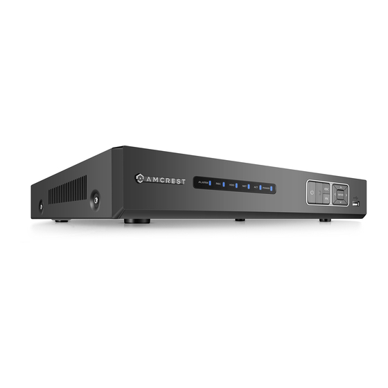
- Page 1 Amcrest AMDV4M4 4MP UltraHD 4CH HDCVI DVR User Manual...
-
Page 2: Table Of Contents
Version 2.0.10 Revised April 12 , 2018 Contents Welcome ....................................4 Important Security Warning .............................. 4 Important Safeguards and Warnings ..........................5 1. Features and Specification ............................. 5 1.1 Overview .................................. 5 1.2 Features ................................... 6 2. Overview and Controls ..............................7 2.1 Front Panel ................................ - Page 3 5.4 Web Access Settings Menu ..........................125 5.5 Web Access Information Menu ........................... 127 5.6 Log Out ................................. 129 6. FAQs/Troubleshooting ............................... 129 Appendix A: Compatible Backup Device List ........................133 Appendix B: Compatible CD/DVD Device List ........................ 139 Appendix C: Compatible Display List ..........................139 Appendix D: Compatible Switch List ..........................
-
Page 4: Welcome
This user manual is applicable to all 4, 8 and 16 channel Amcerst HDCVI DVRs, including any S2, S3, and S4 models. Important Security Warning To keep your Amcrest camera secure and prevent unauthorized access, please make sure to follow the steps below: • Always make sure that your camera has the latest firmware as listed on www.amcrest.com/firmware... -
Page 5: Important Safeguards And Warnings
Be sure to use only the accessories recommended by manufacturer. Before installation, please open the package and check to ensure that all the components are present. Contact the retailer that you purchased from, or Amcrest directly if anything is broken or missing in the package. NOTE: This user manual is applicable to all 4, 8 and 16 channel Amcerst HDCVI DVRs, including any S2, S3, and S4 models. -
Page 6: Features
(trucking), and more. 1.2 Features The Amcrest HDCVI has the following features: • Real-time Monitoring The HDCVI has an analog output port, VGA port, and an HDMI port. You can use a variety of monitors to display the DVR’s interface, and the DVR can support VGA and HDMI output at the same time. -
Page 7: Overview And Controls
• Advanced Network Protocol Support The DVR is UPnP compatible, and includes functionality for use with PPPoE, and DDNS protocols to allow remote and local connection with a large variety of network hardware. Note: There may be slight differences in functionality due to the existence of different product series. 2. -
Page 8: Rear Panel
2.2 Rear Panel 2.2.2 General 720p/1080p 4-Channel System Note: This is for example purposes only, the diagram represents a 4 Channel system however, is applicable to all units provided in the description. The 4-channel system rear panel is as shown below. Please refer to the following table for detailed information: Icon Name... -
Page 9: Device Connection Example
High definition audio and video signal output port. It transmits uncompressed High definition media HDMI high definition video and multiple-channel interface data to the HDMI port of the display device. USB 2.0 port Connect to USB storage device, mouse, burning DVD-ROM etc. Ground end. -
Page 10: Remote Control
2.4 Remote Control The diagram below shows the remote control that comes with the Amcrest HDCVI System. Serial Number Name Function Power button Click it to boot up or shut down the device. Address Click it to input device number, so that you can control Forward Various forward speeds and normal speed playback. - Page 11 In real-time monitor mode, click this button to enter video search menu. Reverse/pause Reverse playback pause mode, click this button to start normal playback. In reverse playback click this button to pause playback. Cancel Go back to previous menu or cancel current operation (close upper interface or control) Record Start or stop record manually...
-
Page 12: Mouse Control
2.5 Mouse Control The following table details the different uses for a computer mouse regarding the DVR’s controls. Left click System pops up password input dialogue box if you have not logged in. In mouse real-time monitor mode, you can go to the main menu. When you have selected one menu item, left click mouse to view menu content. - Page 13 Right click In real-time monitor mode, pops up shortcut menu: one-window, four-window, nine window and sixteen-window, Pan/Tilt/Zoom, color setting, search, record, alarm input, mouse alarm output, main menu. Among which, Pan/Tilt/Zoom and color setting applies for current selected channel. If you are in multiple-window mode, system automatically switches to the corresponding channel.
-
Page 14: Connection And Installation
Please check that all required items for your DVR are present and accounted for. To check what is included with your purchase, go to http://amcrest.com/hdcvi-security-camera-systems.html/ and find the product you purchased, then scroll down and click the “What’s Included” tab. If any item is missing, please contact us as soon as possible so we can send you the missing component. -
Page 15: Connection Port Information
5. Attach the HDD firmly. 6. Connect the HDD cable and power cable. 4. Turn the device upside down and then turn the screws in firmly in the chassis. 8. Secure the screws in the rear 7. Put the cover on in accordance panel and the side panel. - Page 16 The input video signal should have high SNR, low distortion; low interference, natural color and suitable brightness. To guarantee the stability and reliability of the camera signal, the camera should be installed in a cool, dry place away from direct sunlight, flammable materials, explosive substances, etc. The camera and the DVR should have the same grounding to ensure the normal operation of the camera.
- Page 17 3.3.3.2 Audio Output Connection Information The audio output signal parameter is usually over 200mv 1KΩ (BNC or RCA). It can directly connect to a low impedance earphone, active speaker, or amplifier-drive audio output device. If the speaker and the microphone cannot be separated spatially, it may create a feedback loop. In this case you can adopt the following measures: •...
- Page 18 The following interface is based on the 8-channel advanced 1080P (V2) mini 1U Series. Note: The 32-channel alarm interface diagram is shown below, on page 38. ALARM 1 to ALARM 16. The alarms become active in low voltage. 1,2,3,4,5,6, 7,8,9,10,11, 12,13,14,15,16 Three normal open groups (on/off signal) NO1 C1,NO2 C2,...
-
Page 19: Rs485 Port
• RS485 A/B cable is for the A/B cable of the PTZ decoder. T+,T-,R+,R- are four-wire double duplex RS485 port. T+ T-: output wire R+ R-: input wire Relay Specification Model: JRC-27F Silver Material Rating Rated switch capacity 30VDC 2A, 125VAC 1A (Resistance Load) Maximum switch power 125VA 160W... -
Page 20: Dvr Assembly Guide
Note: It is recommended to connect all components of the system as shown below BEFORE mounting any of the cameras. This is to ensure all components are working. If any components are not functioning, please contact Amcrest Support. To set up the DVR hardware, there are 7 major steps: 1. - Page 21 2. Connect a USB mouse to the front of the DVR. 3. Connect an Ethernet cable to your router, and then connect the other end of the cable to the DVR.
- Page 22 4. Connect the camera video extension cable to the camera’s video cable and connect the camera power extension cable to the camera’s power cable. There should be a tag on the video cable to help you make sure the right end of the cable is at hand. 5.
- Page 23 Connect the camera power extension cable to one of the camera power cables, connect this power cable into the power brick, and then plug the cable into an electrical socket.
-
Page 24: Overview Of Navigation And Controls
7. Connect the DVR power cable into the back of the DVR, and then plug in the DVR power adapter into an electrical socket. 4. Overview of Navigation and Controls 4.1 Startup and Shut down 4.1.1 Startup Before initial startup, please make sure: •... -
Page 25: Startup Wizard
• Do not unplug the power cable or click the power on-off button to shut down the device directly when device is running (especially when it is recording.) There are three ways for you to log out. Main menu (RECOMMENDED) From Main Menu->Shut down, select shut down. - Page 26 Main Menu Interface section. • If the password for the administrator account is misplaced, forgotten, or a user is locked out, contact Amcrest Support via one of the following options as a hard password reset may be needed: and use the email form o Visit http://amcrest.com/contacts...
- Page 27 The next screen that comes up is the Record settings screen. Once you are satisfied with the settings on this screen, click the “Next Step” button at the bottom of the screen. The next screen that comes up is the Schedule settings screen. Make sure to click the tabs at the top for Record and Snapshot to configure those settings as well.
- Page 28 The final screen in the setup process is the Network settings screen. Once you are satisfied with the settings on this screen, click the “Finished” button at the bottom of the screen. Once more, note that these settings can be changed at any time by accessing the settings menu.
-
Page 29: Live View
Once the setup process is finished and you have clicked the “Finished” button, you should see the below dialog box: 4.3 Live View When you log in, the system will be in live view mode. You can see the system date, time, channel name and window number. - Page 30 Preview Control Interface Move your mouse near the center at the top of the video of the current channel. You will notice that the system pops up the preview control interface as shown below. If your mouse stays in this area for more than 6 seconds without any action, the control bar will auto-hide. 1.
-
Page 31: Right-Click Menu
Click to take 1-5 snapshots at a time. The snapshot file is saved on the USB device or HDD. You can go to the Search interface to view these snapshots. 4.4 Right-Click Menu By right-clicking the mouse on the screen, the following menu opens up: 4.4.1 Video Viewing Options The DVR supports many different video viewing options of the live streamed channels. - Page 32 Note: The name of the command will be grayed out if the function is not supported. Here you can control PTZ direction, speed, zoom, focus, iris, preset, tour, scan, pattern aux function, light, wiper, rotation, etc. The speed field controls PTZ movement speed. The value ranges from 1 to 8. 8 is the fastest and 1 is the slowest. The remote control’s numeric keypad can be used to enter in a value.
- Page 33 Icon Function Icon Function Preset Flip Tour Reset Pattern Settings Scan Aux on-off button Rotate Go to menu Note: The name of the command will be grayed out if the function is not supported. See below for detailed information on each PTZ function. To configure the functions above, click the Settings button.
- Page 34 To create and manage preset camera configurations, follow the steps below: • Configure the camera positioning as needed. • Click the Set button and then input the preset number. • Click the Set button to save the current preset. • Click Del Preset to delete the current preset.
- Page 35 To create a pattern, click Begin, then use the PTZ controls to move the camera around. Once finished, click End to end and save the pattern. During the use of pattern mode, zoom/focus/iris cannot be modified. 4.4.2.4 Border The border function allows for constraining the area of movement for the cameras during any PTZ function. To set up borders, move the camera using the PTZ controls to the left limit, then click Left to designate that position as the left limit.
-
Page 36: Color Settings
4.4.2.7 Reset The reset button restores the camera to its original configuration settings. 4.4.2.8 Aux On/Off The camera may have an auxiliary function, and this feature enables its use. The aux number corresponds to the device’s slot on the PTZ decoder. 4.4.3 Color Settings Using this screen, the color settings can be configured for the camera display. - Page 37 The following chart shows which settings can be configured by Color Settings: Item Note Period There are two periods in one day. You can set different sharpness, brightness, and contrast setup for different periods. Effective Time Check the box here to enable this function and then set the period time. The value here is used to adjust the sharpness of the video.
-
Page 38: Navigation Bar
4.4.4 Search Please refer to section 4.8.1 for more detailed information. 4.4.5 Manual Recording Please refer to section 4.10.5.3 for more detailed information. 4.5 Navigation Bar To enable Navigation Bar functionality, go to Main Menu -> Settings -> System -> General and check the “Enable Navigation Bar”... -
Page 39: Alarm Status
Click the button and the system goes to the search interface. Please refer to section 4.8.1 for more detailed information. 4.5.6 Alarm Status Click the button and the system goes to the alarm status interface. It is used to view device status and channel status. -
Page 40: Usb Device Auto Popup
4.6 USB Device Auto Popup When you insert the USB device, the system will auto detect it and pop up the following dialogue box. It allows you to conveniently backup files, logs, configurations or update the system. See the image below for the USB Device Popup screen. -
Page 41: Main Menu
4.7 Main Menu The Main Menu Interface is shown below: Below are short descriptions for each of the menu items on the main menu: Operation -> Search: Search and playback recorded video. Operation - > Backup: Backup recorded files onto a CD or USB drive. Operation - >... -
Page 42: Main Menu: Operation
4.8 Main Menu: Operation 4.8.1 Search To access this screen, click the Search button in the Operation row of the Main Menu. The Search screen interface is shown below: Please refer to the following table for more information: Name Function Display Here is where the searched picture or file will be window... - Page 43 • The blue highlighted date means there is picture or file. Otherwise, there is no picture or file. Calendar • In any playback mode, click the date you want to see, and you can see the corresponding recorded file tracers in the time bar. •...
- Page 44 Backward Play In normal play mode, left click the button, the file begins backward play. Click it again to pause current play. In backward play mode, click ►/ to restore normal play. In the playback mode, click it to play the next or the previous section. You can click │/ continuously when you are watching the files from the same channel.
- Page 45 • Select the file(s) you want to backup from the file list. You can mark from the list then click the backup button. Now you can see the backup menu. System supports a customized path setup. After selecting or creating new folder, click the Start button to begin the backup operation.
- Page 46 When the system is in full-screen playback mode, left click the mouse on the screen. Drag your Digital mouse to select a section and then left click the mouse to activate digital zoom. You can right zoom click the mouse to exit. Manually switch During the file playback process, you can switch to another channel via the dropdown list or...
- Page 47 This feature allows for searching through recordings by time stamp. Select recordings from one day, click advanced search, and go to the file list interface. The user can input the time at the top right corner to search recordings by time. See image on the left side of the images below. For example, inputting the time 11:00.00 and then clicking the Search button allows for viewing all of the recorded files after 11:00.00 (The recordings include current times).
- Page 48 While in 1-window playback mode, click mark file list button to go to the marked file list interface. Double click one-mark file and you can begin playback from the marked time. • Marks Manager Click the mark manager button on the Search interface; you will go to the Marks Manager interface. The system can manage all the recorded mark information of the current channel by default.
- Page 49 4.8.2 Backup The DVR supports backup of recorded files to CD-RWs, DVDs, USB devices, eSATA devices, and through network download. In this section, USB and eSATA backup will be discussed. Network download backup options are discussed in Chapter 5 of this user manual. Clicking the backup button from the Main Menu opens the Backup screen.
- Page 50 To start the backup, click the backup button on the bottom right of the screen. Once the backup button is clicked, the backup will begin, and the backup button turns into a stop button that allows for the cancellation of the backup.
-
Page 51: Main Menu: Information
Tip: • During the backup process, the user can click ESC to exit the current interface to use the DVR for other functions. The system will not terminate the backup process. 4.8.3 Shut down From the Main Menu, clicking the Shut down button will result in the appearance of a box with three options: The Shut down option turns off the DVR. -
Page 52: Hdd Information
4.9.1.1. HDD Information • SATA: o This shows how many hard drives the system can support. o 1 here means the system supports a maximum of 1 HDD. The symbol on the next row shows the status of the connected hard drive. ▪... - Page 53 4.9.1.2 Record Info This screen is used to view information on recorded video, specifically recording start time and end time for all media based on each hard drive.
- Page 54 4.9.1.3 BPS On this screen, current video data stream information can be viewed, as well as resolution used for each camera. All data is measured in Kilobytes per Second (KB/s). 4.9.1.4 Version This screen shows version information for the DVR. Here information such as device model, channels, system version, build date, web interface version, and serial number can be found.
- Page 55 4.9.2 Event This screen is used to display device and channel status. 4.9.3. Network This screen is used to display network information. It consists of 3 screens, Online Users, Load, and Test. 4.9.3.1 Online Users This screen is used to monitor and manage users who are online. With the proper system access level, users can be disconnected or blocked.
-
Page 56: Network Load
4.9.3.2 Network Load This screen shows the amount of bandwidth consumed on the network by the DVR. The connection status is shown as offline if the DVR is disconnected from the internet. The bottom panel is a graph that shows the fluctuation in the send and receive speed. - Page 57 Below is an explanation of each of the fields: • Destination IP: Input a valid IPV4 address or domain name to test connection with. • Test: This button is clicked to test the connection with the destination IP address. The test results can display average delay and packet loss rate, and network status can be viewed.
-
Page 58: Main Menu: Settings
Note: The system can only show a maximum of 100 logs on one page. The system can save a maximum of 1024 log files. Using the fields at the top of the page, the user can search for log items, and view details for each one. Start Time and End Time allow the user to narrow the range in which a log item resides, and the Type dropdown box allows for filtering on what type of event the user is looking for. - Page 59 Below is an explanation for each of the fields on the Image Settings screen: • Channel: This dropdown box allows the user to select a channel from the dropdown list to modify. • Period: This dropdown box allows the user to select a period for which to modify the image settings. The user can configure up to 2 periods to encompass the entire 24 hours in the day.
- Page 60 4.10.1.2 Encode This tab is used to set the video encoding settings for each channel. See below for a screenshot of the tab: Below is an explanation of the fields on the Encode settings screen: • Channel: This dropdown box allows the user to select a channel from the dropdown list to modify. •...
- Page 61 4.10.1.3 Snapshot This tab allows for the selection of snapshot settings. See below for a screenshot of the Snapshot tab: Below is a list of snapshot settings that can be modified on this screen: • Snapshot Mode: This dropdown box allows the user to select a snapshot mode. There are two snapshot modes: regular and trigger.
- Page 62 4.10.1.4 Overlay The overlay tab allows the user to change overlay settings for each channel. Below is a screenshot of the overlay tab: Below is an explanation of fields that can be modified on the overlay settings screen: • Channel: This dropdown box allows the user to select a channel from the dropdown list to modify. •...
- Page 63 To confirm settings, click the Save button. To revert to default settings, click the Default button. To revert to default settings, click the Default button near the bottom left hand corner. To copy settings to another channel, click the Copy button near the bottom right hand corner. To confirm settings, click the Save button near the bottom right hand corner.
- Page 64 bottom right hand corner. To apply the settings, click the Apply button near the bottom right hand corner. After completing the setup please click the save button to go back to the previous menu. 4.10.2 Network This menu controls all network related functions for the DVR and governs how the DVR interacts with the network it is connected to.
- Page 65 The P2P settings screen is where users can use a QR code to connect their smartphone or tablet to the DVR. The HDCVI uses an app called Amcrest View, and it is available on both iOS and Android. Below is a screenshot of the P2P settings...
- Page 66 Below is an explanation of the fields on the P2P settings screen: • Enable: This checkbox allows the user to enable the P2P feature for the DVR. • Connect Status: This field shows the status of the P2P connection. Once connected using the app, this field should display the word Online •...
- Page 67 corner. To apply the settings, click the Apply button near the bottom right hand corner. After completing the setup please click the save button to go back to the previous menu. 4.10.2.4 PPPoE PPPoE stands for Point-to-Point Protocol over Ethernet. This screen allows users to configure PPPoE connections. Below is a screenshot of the PPPoE screen: To revert to default settings, click the Default button near the bottom left hand corner.
- Page 68 Below is an explanation of the fields that can be configured on DDNS settings screen when set to Quick DDNS type. Fields with a ‘*’ next to them appear when Quick DDNS is selected: • Enable: This checkbox allows the user to enable DDNS on the DVR. •...
- Page 69 Below is an explanation of fields on the IP Filter settings screen: • Enable: This checkbox allows the user to enable the IP Filter feature. Many of the other fields below cannot be edited if this checkbox is not checked. •...
- Page 70 To revert to default settings, click the Default button near the bottom left hand corner. To test the current settings, click Test near the bottom left hand corner. To confirm settings, click the OK button near the bottom right hand corner. To cancel any modifications, click the Cancel button near the bottom right hand corner. To apply the settings, click the Apply button near the bottom right hand corner.
- Page 71 Event Interval: This field allows the user to define, in seconds, how many events can be triggered concurrently. • Health Enable: This checkbox allows the user to enable the function that causes the system to send out a test email to ensure if the connection is OK or not. •...
- Page 72 • Image Upload Interval: This field allows the user to define, in seconds, how often images can be uploaded to the FTP server. • Channel: This field allows the user to pick a channel to set FTP settings for. • Weekday: This field allows the user to pick a day of the week to set FTP settings for.
- Page 73 Cancel button near the bottom right hand corner. To apply the settings, click the Apply button near the bottom right hand corner. To view a video on how to remotely access your DVR using UPnP, go to http://amcrest.com/videos and view the video titled “How to Gain Remote Access to Your HDCVI DVR with Universal Plug and Play”.
- Page 74 4.10.2.10 SNMP SNMP stands for Simple Network Management Protocol. This protocol is used to provide a basic framework to allow connection between various network devices. Below is a screenshot of the SNMP settings screen: Use of SNMP required additional software to create a Management Information Base (MIB) database. A popular set of tools for this purpose are MIB Builder and MG-SOFT MIB Browser.
- Page 75 • Write-Community: This field allows the user to specify which user community has write access. • Trap Address: This field allows the user to enter the IP address of the PC running the MIB software. • Trap Port: This field allows the user to enter the port number of the PC running MIB software. To revert to default settings, click the Default button near the bottom left hand corner.
- Page 76 Well-known IPv6 multicast addresses Address Description ff02::1 All nodes on the local network segment ff02::2 All routers on the local network segment ff02::5 OSPFv3 All SPF routers ff02::6 OSPFv3 All DR routers ff02::8 IS-IS for IPv6 routers ff02::9 RIP routers ff02::a EIGRP routers ff02::d...
-
Page 77: Alarm Center
Below is an explanation of the fields on the Register settings screen: • Enable: This checkbox allows the user to enable the Register feature for the DVR. • No: This dropdown box allows the user to select the proxy number. Currently the DVR can only configure one proxy. - Page 78 The P2P settings screen is where users can use a QR code to connect their smartphone or tablet to the DVR. The HDCVI uses an app called Amcrest View, and it is available on both iOS and Android. Below is a screenshot of the...
- Page 79 Below is an explanation of the fields on the P2P settings screen: • Enable: This checkbox allows the user to enable the P2P feature for the DVR. • Connect Status: This field shows the status of the P2P connection. Once connected using the app, this field should display the word Online.
-
Page 80: Motion Detect
4.10.3 Event 4.10.3.1 Detect Main Menu -> Settings -> Event -> Video Detect opens the Detection interface. Here there are 3 options, each representing a detection type: Motion Detection, Video Loss, and Tampering. Tips: • The motion detection icon will be present if the motion detection alarm has been triggered on the current channel. - Page 81 Below is a description of the fields on the Motion Detection settings page: • Enable: This checkbox allows the user to enable the motion detection function for a specific channel. To select a channel, click on the drop-down menu provided on the right. •...
- Page 82 period. To copy time periods, click the checkboxes next to the days of the week that you’d like to copy the settings to. Once finished on this screen, click Save to return to the time period settings screen. • Anti-Dither: This field allows the user to set the anti-dither time. The values in this field can range from 5 to 600 seconds.
- Page 83 detection zones will not go into effect. Clicking the escape button to leave the motion detection zone and will not save the zone setup. • Record Channel: This checkbox allows the user to enable the system to record video for that channel when a motion detection alarm is triggered.
- Page 84 Below is a description of the fields on the Video Loss settings page: • Enable: This checkbox allows the user to enable the motion detection function for a specific channel. To select a channel, click on the drop-down menu provided on the right. •...
- Page 85 To specify time zones in greater detail for each day, click the Setup button to the left of the time bar, and the Time Period setup screen will appear. The screenshot below shows the Time Period settings screen: The system allows for the configuration of up to 6 different time periods. Click the checkbox to the left of the time period to enable that time period.
- Page 86 To revert to default settings, click the Default button near the bottom left hand corner. To copy settings to another channel, click Copy near the bottom left hand corner. To test a channel’s motion detection, click Test near the bottom left hand corner. To confirm settings, click the OK button near the bottom right hand corner. To cancel any modifications, click the Cancel button near the bottom right hand corner.
- Page 87 Click and drag on the green bars to specify time zones for motion detection. To edit multiple days at once, either click the checkboxes next to the names, or click the checkbox next to All to edit all the days at once. Once the checkbox is clicked, press save to save and apply your detection settings. Click Cancel to undo any changes and return to the motion detection settings screen.
- Page 88 second, the buzzer, tour, PTZ activation, snapshot, record channel functions will begin another 10 seconds while the screen prompt, alarm upload, email will not be activated again. After 10 seconds, if system detects another alarm signal, it can generate a new alarm since the anti-dither time has expired.
- Page 89 Below is an explanation of the fields on the HDD Abnormality settings screen: • Event Type: This field allows the user to specify which HDD abnormality event type they would like to configure settings for. o No Disk: No hard drive is detected. o Disk Error: The hard drive has an error.
- Page 90 Below is an explanation of the fields on the Network Abnormality settings screen: • Event Type: This field allows the user to specify which Network abnormality event type they would like to configure settings for. Net Disconnected: The network connection has been disconnected. o IP Conflict: There is a device on the network with the same IP address.
- Page 91 4.10.4.1 Schedule This screen is used to specify the recording schedule for both recorded video and snapshots. Below is an explanation of the fields on the Record settings screen: • Channel: This dropdown box allows the user to pick which channel they would like to change video recording settings for.
- Page 92 Click the text next to each period to edit the time you wish to set for that specific period. Next, choose which record type you would like to set for each period. You will also need to select the days you wish to apply these settings.
- Page 93 Note: Prior to setting up a schedule for snapshots in this menu, it is highly recommended to do the following 3 steps. 1. Go to Main Menu -> Settings -> Storage -> Record and enable snapshot for any channels that may be using this feature.
- Page 94 To revert to default settings, click the Default button near the bottom left hand corner. To copy settings to another channel, click Copy near the bottom left hand corner. To confirm settings, click the OK button near the bottom right hand corner. To cancel any modifications, click the Cancel button near the bottom right hand corner.
- Page 95 • Hard Drive List: This shows what hard drives are currently connected to the DVR, and displays information about them. Device Name: This column shows the names of the connected hard disk drives (HDD). Type: This column shows the type of access the DVR has to the hard drive. To change a hard drive’s type, click the downward arrow next to the HDD’s type and select the desired type.
- Page 96 Below is an explanation of all of the fields on the Record settings page: • Main Stream: The main stream is the stream through which the channels transmit data by default. There are 3 settings that can be used for the main stream. Schedule: Channels will record as they have been scheduled, and not in any other capacity.
- Page 97 Below is an explanation of the fields on the HDD Detect settings page: • Type: This dropdown box allows the user to select which type of HDD detection report to run. There are two options: Quick Detect: Quick detect runs a quick hard drive error detection report. Full Detect: Full detect runs a more detailed hard drive error report and may take more time.
- Page 98 The Detect Results tab shows a visual representation of the hard drive scan results. The S.M.A.R.T. tab shows S.M.A.R.T. report results. For more information on S.M.A.R.T., see section 4.9.1.1. The S.M.A.R.T. tab looks like the screenshots below: 4.10.5 System 4.10.5.1 General This screen displays general settings for the DVR.
- Page 99 Below is an explanation of the fields on the General settings screen: • Device ID: This field allows the user to customize the name of the HDCVI. • Device No: This field allows the user to customize the device’s number. •...
- Page 100 4.10.5.2 Date & Time This screen displays date and time settings for the DVR. Below is a screenshot of the Date & Time settings screen: Below is an explanation of the fields on the Date & Time settings screen: • Date Format: This dropdown box allows the user to specify a date and time format for the DVR to use.
- Page 101 • DST Type: This field allows the user to pick whether DST starts on a specific day of the week, or on a specified. • Start Time: This field allows the user to enter a start date and time for DST to begin. •...
- Page 102 • Date: This column shows the date that the holiday occurs on. • Period: This column shows the range in which the holiday occurs. • Edit: This column has a button that allows for the editing of the holiday. • Delete: This column has a button that allows for the deletion of the holiday.
- Page 103 4.10.5.4 Display This screen is used to set display settings for the DVR. Below is a screenshot of the display settings screen: Below is an explanation of the fields on the Display settings screen: • Transparency: This slider allows the user to change the transparency of the menu screens on the DVR. The range goes from 0% to 100%.
- Page 104 Below is an explanation of the fields on the Tour Setup settings screen: • Enable Tour: This checkbox allows the user to enable the tour functionality. An alternate way to enable or disable tour is by clicking on the navigation bar. •...
- Page 105 Below is an explanation of the fields on the Zero-Channel Encoding settings screen: • Enable: This checkbox allows the user to enable the zero-channel encoding functionality. • Compression: This dropdown box allows the user to select the compression settings used by the system for zero-channel encoding.
- Page 106 4.10.5.7 Pan/Tilt/Zoom This screen is used to configure Pan/Tilt/Zoom (PTZ) functionality. Below is a screenshot of the PTZ settings screen: Below is an explanation of the fields on the PTZ settings screen: • Channel: This dropdown box allows the user to pick which channel they would like to change PTZ settings for. •...
-
Page 107: Text Overlay
4.10.5.8 Text Overlay This screen is used to configure Text Overlay settings. This allows the DVR to record data brought in from Automated Teller Machines (ATMs) or Point of Sales (POS) systems and overlay the text onto the recorded video. Below is a screenshot of the Text Overlay settings screen: Below is an explanation of the fields on the Text Overlay settings screen: •... - Page 108 4.10.5.9 Account This menu is used to manage user accounts, user account passwords, and user groups. Below are a few considerations to keep in mind when editing this information: • The DVR comes with 2 usernames by default: o Username: admin Password: admin o Username: default Password: default •...
- Page 109 4.10.5.10 User This screen is used to configure User Account settings. Below is a screenshot of the User Account settings screen: Below is an explanation of the fields on the User Account settings screen: • Number: This number indicates how many users are in the system. Each line item has a number to signify its place in the list.
- Page 110 Note: It is recommended to give the general user fewer rights than an administrative one. When a new user is created, a MAC address can be entered for the user. This can limit the user's ability to logon from another device.
-
Page 111: Auto Maintain
• Delete: This column has a button that allows for the account's properties to be deleted. • Memo: This column indicates any notes about the user group. • Add Group: This button allows the user to add another user group. On the next page is a screenshot of the Add Group screen. - Page 112 Below is an explanation of the fields on the Auto Maintain settings screen: • Auto Reboot System: This dropdown field allows the user to set a day of the week and time to automatically reboot the system to keep the system healthy. •...
- Page 113 Below is an explanation of the fields on the Config Backup settings screen: • Device Name: This dropdown field allows the user to select a device to pull configuration data from. • Refresh: This button refreshes the list of devices connected to the DVR. •...
- Page 114 There are 5 different settings areas that can be reset to default settings: Camera settings, Event settings, Network settings, System settings, and Storage settings. All of these settings can be reset by the use of the All checkbox. The following settings are also reset with a factory reset: •...
-
Page 115: Web Operation
5 Web Operation One of the main features of the Amcrest HDCVI DVR is the ability to access the DVR and all its features through the web. Whether you want to view the live feed from remote location, or you want the ability to display the live feed on multiple computers on your local network, the Amcrest HDCVI DVR can accommodate all those needs. -
Page 116: Remote Web Access
15. Once the main interface opens, click the plug icons next to each camera on the list on the left hand side, and activate the main stream for each of them to enable the live feed. If the process above is not working, please contact Amcrest Support via one of the following options: •... - Page 117 For more information on UPnP, see section 4.10.2.8. For more information on DDNS, see section 4.10.2.4. If the process above is not working, please contact Amcrest Support via one of the following options: •...
- Page 118 5.2.2 Port Forwarding Remote Access Setup Port Forwarding is an alternative method to setting up remote access for the Amcrest HDCVI DVR. This method should only be used if the UPnP/DDNS Remote Access method did not work. For more information on how to setup the DVR using this method, see section 5.2.1.
-
Page 119: Web Access Interface
26. Once the main interface opens, click the plug icons next to each camera on the list on the left hand side, and activate the main stream for each of them to enable the live feed. If the process above is not working, please contact Amcrest Support via one of the following options: •... - Page 120 Logout: This button logs the user out of the system. See section 5.6. 2. Channel List: On this side bar, there is a list of all the channels available, as well as an Open All button. The Open All button enables/disables real-time channel monitoring for all of the channels. To switch between the main stream and the sub stream, click the channel name and select which stream to use.
- Page 121 There are minor differences between the LAN and WAN Live View Interfaces. The interface on the WAN Live View consists of 7 major sections: 1. Menu Bar: There are 6 menu items on the menu bar. Live: This button takes the user to the Live View interface (pictured above) b.
-
Page 122: Playback Interface
5.3.3 Playback Interface This is the interface for the DVR web access playback menu. There are 6 main sections: 1. View Selection: This panel allows the user to view the different channel layouts. 2. Calendar: This panel allows the user to pick a date that they would like to playback video from. 3. - Page 123 This allows the user to select files for download. Select the files by clicking the checkbox next to each file, and then click download to download the files to the PC. Clicking more, opens the advanced download screen where the user can download individual files, download by time frame, or add a watermark to a video.
- Page 124 This is the Watermark screen. This screen allows users to add a watermark to downloaded video, and to verify watermarked videos.
-
Page 125: Web Access Settings Menu
5.3.4 Alarm Interface This is the interface for the DVR's Alarm management menu. There are 4 main sections. See the table below for more information: Number Section Parameter Function Alarm Video loss The system triggers the alarm when video loss occurs. Type Motion detection The system triggers the alarm when motion detection... -
Page 126: Camera Settings
To access the web access settings menu, click the gear icon near the top right hand corner of the web access interface. 5.4.1 Camera Settings 5.4.1.1 Image Settings This screen is allows the user to adjust the image settings for each channel. See below for a screenshot of the image settings screen: Below is an explanation for each of the fields on the Image Settings screen: •... -
Page 127: Web Access Information Menu
• Sharpness: This slider is used to adjust the sharpness of the video. The value ranges from 0 to 100. The larger the value is, the clearer the edges are and vice versa. Note: The higher the value, the higher likelihood of picture noise occurring. -
Page 128: Online Users
The system lists the following information: • System Operation • Account Manager • Configuration Operation • Log Clear • Data Management • File Operation • Alarm Events • Reboot Type • Record Operation Below is an explanation of the fields on the log screen: Parameter Function Type... -
Page 129: Log Out
5.6 Log Out The logged in user can logout by using the button near the top right hand corner of the screen. Once logged out, the DVR Web Access will return to the login screen, where another user may login. Below is a screenshot of the login screen: 6. - Page 130 • The hard drive is broken. • The hard drive cable is damaged. • The hard drive cable connection is loose. • The DVR's main motherboard SATA port is broken. 4. There is no video output on any of the channels. Below are a few possible reasons why this may be occurring: •...
- Page 131 • The corresponding channel may not have any audio input. 10. The timestamp is not displaying the correct time. Below are a few possible reasons why this may be occurring: • The time and date settings may not be configured correctly. •...
- Page 132 The PC may not have DirectX 8.1 or higher. • The PC may not have Windows XP or higher. 23. Forgot local menu operation password or network password Please contact Amcrest support to reset the DVR's password. To contact Amcrest support, please do one of the following:...
-
Page 133: Appendix A: Compatible Backup Device List
• Visit http://amcrest.com/contacts and use the email form • Call Amcrest Support using one of the following numbers Toll Free: (888) 212-7538 International Callers (Outside of US): +1-713-893-8956 USA: 713-893-8956 Canada: 437-888-0177 UK: 203-769-2757 • Email Amcrest Customer Support support@amcrest.com 24. - Page 134 Maxell USB Flash Stick Maxell USB Flash Stick Kingax Super Stick 128M Kingax Super Stick 256M Kingax Super Stick 512M Kingax Super Stick Kingax Super Stick Netac U210 128M Netac U210 256M Netac U210 512M Netac U210 Netac U210 Netac U208 Teclast Ti Cool...
- Page 135 Kingston Sandisk SDHC2 Micro-SD Sandisk Micro-SD Compatible Portable HDD List Please refer to the following sheet for compatible portable HDD brands. Brand Model Capacity YDStar YDstar HDD box Netac Netac Iomega Iomega RPHD-CG" RNAJ50U287 250GB WD Elements WCAVY1205901 1.5TB Newsmy Liangjian 320GB WD Elements...
- Page 136 Compatible SATA HDD List NOTE: Please upgrade the DVR firmware to latest version to ensure the accuracy of the table below. SATA hard drives should be connected to the DVR's SATA port. It is recommended to use a hard drive with a capacity between 500 gigabytes and 4 terabytes.
- Page 137 Seagate Seagate Pipeline HD2 ST2000VM002 SATA Seagate Seagate Pipeline HD2 ST2000VM003 SATA Seagate Seagate Constellation ST3500514NS 500G SATA Seagate Seagate Constellation ST31000524NS SATA Seagate Seagate Constellation ST32000644NS SATA Seagate Seagate Constellation ST2000NM0011 SATA Seagate Seagate Constellation ST1000NM0011 SATA Seagate Seagate Constellation ST500NM0011 500G SATA...
- Page 138 Westem Digital Cariar SE16 WD5000KS 500G SATA Westem Digital Cariar SE16 WD4000KD 400G SATA Westem Digital Cariar SE16 WD3200KS 320G SATA Westem Digital Cariar SE16 WD2500KS 250G SATA Westem Digital WD Caviar SE16 WD2500YS-01SHB0 250G SATA Westem Digital WD Caviar RE16 WD3200YS-01PGB0 320G SATA...
-
Page 139: Appendix B: Compatible Cd/Dvd Device List
Samsung Samsung—HD HD154UI/CE 1.5T SATA Hitachi HitachiCinemaStar™ HCP725050GLA380 500G SATA 5K500 Hitachi HitachiCinemaStar™ HCT721050SLA360 500G SATA 7K1000.B Hitachi HitachiCinemaStar™ HCT721075SLA360 750G SATA 7K1000.B Hitachi HitachiCinemaStar™ HCT721010SLA360 SATA 7K1000.B Maxtor DiamondMax 20 STM3320820AS 320G SATA Maxtor DiamondMax 20 STM3250820AS 250G SATA Appendix B: Compatible CD/DVD Device List NOTE: Please upgrade the DVR firmware to latest version to ensure the accuracy of the table below. -
Page 140: Appendix D: Compatible Switch List
Q7T4 17-inch BENQ(LCD) Q7T3 17-inch BENQ(LCD) LXB-L17C 17-inch LENOVO(LCD) 225BW 22-inch (wide screen) SANGSUNG(LCD) HFNOVO (CRT) LXB-FD17069HB 17-inch HFNOVO (CRT) LXB-HF769A 17-inch HFNOVO (CRT) LX-GJ556D 17-inch 2494HS 24-inch Samsung(LCD) P2350 23-inch Samsung(LCD) P2250 22-inch Samsung(LCD) P2370G 23-inch Samsung(LCD) Samsung(LCD) 2043 20-inch 2243EW 22-inch... -
Page 141: Appendix E: Compatible Wireless Mouse List
5、 FULL-100M H3C-S1024 10/100M self-adaptive TP-LINK TL-SF1016 10/100M self-adaptive TP-LINK TL-SF1008+ 10/100M self-adaptive Appendix E: Compatible Wireless Mouse List Please refer to the following sheet for compatible wireless mouse brands. Brand Model Rapoo 3500 Logitech M215 Shuangfeiyan Tianyao G7-630 Appendix F: Toxic or Hazardous Materials or Elements Toxic or Hazardous Materials or Elements Component Name... - Page 142 All the designs and software here are subject to change without prior written notice. • All trademarks and registered trademarks mentioned are the properties of their respective owners. • If you have any questions or concerns, please contact us at support@amcrest.com, or call us at 888212-7538. Copyright © Amcrest 2018...
Need help?
Do you have a question about the AMDV4M4 and is the answer not in the manual?
Questions and answers