AUTOHELM ST50 PLUS Operation And Installation Manual
Hide thumbs
Also See for ST50 PLUS:
- User manual (17 pages) ,
- Operation and installation (47 pages) ,
- Operation and installation (18 pages)

Related Manuals for AUTOHELM ST50 PLUS


Summary of Contents for AUTOHELM ST50 PLUS
- Page 1 Distributed by Any reference to Raytheon or RTN in this manual should be interpreted as Raymarine. The names Raytheon and RTN are owned by the Raytheon Company.
- Page 2 RADAR Operation and Installation...
- Page 3 ST50 PLUS RADAR Operation and Installation Handbook Autoheims poiicy of continuous improvement and updating may change product specifications without prior notice Copyright Autohelm 1994...
- Page 4 ST50 PLUS RADAR Operation and Installation Handbook Warning This radar equipment must be installed and operated in accordance with the instructions contained in this manual. Failure to do so can result in personal injury and/or navigational inaccuracies. In particular: 1. HIGH VOLTAGE. The radar display unit contains high voltage.
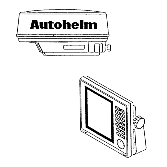
- Page 5 ST50 PLUS RADAR Operation and Installation Handbook ST50 PLUS RADAR Operation and Installation Handbook Package Contents 1. Display Unit 2. Scanner Unit Inter unit Cable (15m) Power Cable Fixing Studs (4 chl) Thumb nuts (4 off) Gasket Template 10. Installation and Operation Handbook 11.
-
Page 6: Table Of Contents
Contents Contents Section 1. Introduction ........... l - l 1.1 General ..............1.2 Equipment Features ..........1.2.1 ST50 Display Unit ........... 1.2.2 Radome Antenna Unit Main Features ....l-4 1.3 About This Manual ..........1.4 Specifications ............1.4.1 General ............1.4.2 Display Unit ............ - Page 7 ST50 PLUS RADAR Operation and lnstalfation Handbook Radar Glossary Radar Glossary Section 3. Operation ............. 3.1 Introduction ............The following is a list of abbreviations and acronyms which may be 3.2 Radar Map ............. used in the text of the manual.
-
Page 8: Section 1. Introduction
Section 1. Introduction Section 1. Introduction 1.1 General Congratulations on selecting the Autohelm ST50 LCD Radar for your radar navigation needs. Whether you purchased this radar because of its compactness, power economy, ease of installation, or long term reliability, one thing is certain;... -
Page 9: Equipment Features
Section 1. Introduction ST50 PLUS RADAR Operation and lnstaNation Handbook 8. Interfaces with Autohelm Seatalk instruments, and NAVAIDS, chart information, making navigation both informative and exciting. including Autohelm’s Smart Heading Sensor magnetic compass. The unique Split Screen Mode allows simultaneous viewing of radar and Seatalk’... -
Page 10: Radome Antenna Unit Main Features
Section 1. Introduction ST50 PLUS RADAR Operation and Installation Handbook The compact design of the display unit is made possible by the use of 1.3 About This Manual custom LSI (Large Scale Integrated circuit) components. An LSI type This manual contains important information to help you get the best of “chip”... -
Page 11: Specifications
ST50 PLUS RADAR Operation and fnstallation 1 - 6 Section 1. Introduction Handbook 1.42 Display Unit 1.4 Specifications Dimensions: Width 208 mm (8.2’) 1.4.1 General Depth 68 mm (2.7’) Height 198 mm (7.8’) Less than 35 m (25 yds) on the... -
Page 12: Radome Antenna
Section 1. Introduction ST50 PLUS RADAR Operation and Installation Handbook l - 8 Cursor, VRM, EBL, Interference Rejection, 1.4.3 Radome Antenna Target Expansion, Target Alarms, LAT/ Dimensions: Diameter of radome 450 mm (17.7’) LONG or TD Readouts, Waypoint t/L, Off Height mm (8.9’) -
Page 13: Section 2. Installation
Section 2. Instal/ation Section 2. Installation 2.1 General Congratulations on selecting the Autohelm ST50 LCD radar to meet all of your radar navigation requirements. Although your ST50 radar is designed to the highest levels of quality and performance, it can only attain those standards when a proper installation of the equipment has been achieved. -
Page 14: Planning The Installation
2 - 3 Section 2. Installation ST50 PLUS RADAR Operation and Installation Handbook 2.3 Planning the Installation The layout for installing the ST50 radar should be planned to give the best operation and service aboard your particular vessel. In general, the Radome Unit should be mounted as high as possible above the waterline. - Page 15 Section 2. Installation ST50 PLUS RADAR Operation and Installation Handbook 2 - 5 that may cause interference, such as motors and generators. 6) Generally speaking, the display should be located in a protected area away from prolonged direct exposure to rain and salt spray.
-
Page 16: Console Mounting Instruction
2 - 6 ST50 PLUS RADAR Operation and Installation Handbook Section 2. lnstaflation 2 - 7 Instructions 2. Unpack the template mounting kit and also confirm that all 2.3.1.1 Console Mounting hardware is present. The procedure below can be used to console mount the ST50 Display. - Page 17 2 - 8 Section 2. Installation Warning It is recommended that the radar antenna be mounted above objects which could interfere with the radar signal such as the flying bridge, large engine stacks, and personnel. This may be difficult on some vessels and in such a case it is recommended that a radar mounting pedestal be used.
- Page 18 ST50 PLUS RADAR Operation and Installation Handbook Section 2. Installation Using the outline drawing of the Scanner base or template in the back Some vessel’s however, may adopt a HIGHER BOW angle when the vessel is at it’s cruising speed that substantially alters and raises the of the manual as a guide, prepare the mounting surface with the four mounting holes as required.
- Page 19 Section 2. installation ST50 PLUS RADAR Operation and installation Handbook The cable entrance is provided at the rear of the radome unit. If the unit Step 1. Loosen the 4 clamping bolls is mounted on a hollow mast, the cable may be run inside the mast and securing the radome and remove the then fed through the radar’s cable entrance.
-
Page 20: Electrical Connection
Section 2. Installation ST50 PLUS RADAR Operation and Installation Handbook 2.4 Electrical Connections , ANTENNA UNIT D I S P L A Y U N I T ; 2.4.1 DC Power Connection T ELK The ST50 is intended for use on DC ships power systems and can operate as long as that DC supply system is maintained from 10.2 to... -
Page 21: External System Interface
ST50 PLUS RADAR Operation and installation Handbook Section 2. Installation Should the power connections be accidently reversed, protective in- The ST50 radar can receive various input signals from Navaids, Flux line fuse F401(3.15A) will blow. Make sure that the input power leads Sensors, Raychart Units, and Seatalk Data networks. -
Page 22: Installing The Xx Heading Sensor
Section 2. Installation ST50 PLUS RADAR Operation and Installation Handbook If for some reason, NMEA 0183 data is not available from any Navaids on the vessel, the radar can accept and operate in full function with the 2.4.2.2 Installing the XX Heading Sensor The sensor should be placed in a location on the vessel where magnetic interference is minimal and where it will remain undisturbed. -
Page 23: Interconnection Xx Heading Sensor
Section 2. Installation ST50 PLUS RADAR Operation and Installation Handbook Notes: The sensor is designed to output the NMEA 0183 “HDM” Drill a 9/64’ hole in the center of each of the three slotsin the base sentence for the radar. The sensor can supply data for up to two (2) of the sensor. -
Page 24: Seatalk/Compass Interface
TERMINAL In order to view Seatalk data on the bottom of the ST50 display, a simple connection to your existing Autohelm capable equipment is all that is required. Once connected, you simply need to select “DISPLAY RADAR SEATALK” by held depressing ml key or from the MAIN menu in order to see the split screen capabilities of the ST50. -
Page 25: Section 3. Operation
Raychart option kit 3.1 Introduction MDYW10417. Congratulations on selecting the Autohelm ST50 LCD Radar to When the Raychart unit is first turned on, the radar will detect the fulfill all of your radar navigation requirements. -
Page 26: Radar Map
ST50 PLUS RADAR Operation and Installation Handbook Section 3. Operation 3 - 2 3.2.2 Effect of Ship’s Movement 3.2 Radar Map Radar Displays can be drawn in two ways to show the ship’s motion, The radar display is a map-like representalion of the area in which the The displays are called “Relative Motion”... -
Page 27: Sea Return
ST50 PLUS RADAR Operation and Installation Handbook Section 3. Operation Buoys and small boats are an example of targets that are sometimes 3.2.6 Blind Sectors or Shadow Effect difficult to differentiate between. Since they bob and toss about in the Not all echoes on the radar are direct returns to the radar antenna. -
Page 28: Side Lobes
ST50 PLUS RADAR Operation and Installation Handbook Section 3. Operation 3 - 6 3.2.8 Radar Interference 3.2.7 Side Lobes A very small part of the RF energy from each transmitted pulse is Whenever two or more radar equipped vessels are operating within radiated outside the single narrow beam, producing side lobe patterns. -
Page 29: Determining Radar Line-Of-Sight Range
Section 3. Operation ST50 PLUS RADAR Operation and Installation Handbook 3 - 8 Indirect echoes may appear when there is a large target, such as a 3.2.10 Determining Radar Line-of-Sight Range passing ship at a short range, or a reflecting surface, such as a funnel When searching for distant echoes, the radar line-of-sight range to the on your own ship in line with the antenna. -
Page 30: Operating Controls
Section 3. Operation ST50 PLUS RADAR Operation and Installation Handbook By pressing and holding down the STBY/XMIT key indication A 5 meter cliff has a radar horizon of 5 nm. Therefore, under standard approximately 2 seconds, the radar will be turned OFF and all conditions, the cliff should begin to appear on the screen when the ship alphanumeric information on-screen will extinguish. - Page 31 Section 3. Operation ST50 PLUS RADAR Operation and Installation Handbook TUNE CONTROL Note: Pressing the [G-l key at the same time while turning the radar to standby will perform a Soft Master Reset to the unit The tune control is used to tune the receiver in the antenna unit in the event that a “lock up”...
- Page 32 Section 3. Operation ST50 PLUS RADAR Operation and Installation Handbook The gain control adjusts the gain of the receiver, by increasing or The sea clutter control, also known as the Sensitivity Time Control decreasing the strength of the incoming video and noise. The gain clutter close to own ship by reducing the nearby gain.
- Page 33 Section 3. Operation ST50 PLUS RADAR Operation and Installation Handbook 3 - 1 6 If the m key is pressed the EBL will be displayed as a “Dashed” You can move the CURSOR to the start point by using arrow keys line and ‘EBL’...
- Page 34 Section 3. Operation ST50 PLUS RADAR Operation and Installation Handbook The Off Center Mode does not operate on the 16 nm range and cannot be used together with the ZOOM mode. The Cursor feature combines the EBL and VRM functions and can...
- Page 35 Section 3. Operation ST50 PLUS RADAR Operation and Installation Handbook 3 - 2 1 You can select each item with keys and change with keys. After setting you can return by pressing[m]key again. The This CONT/DIM key is used to adjust the contrast of LCD or the selected position changes reverse character and the set characters backlight brilliance of LCD and key pad.
- Page 36 3 - 2 3 ST50 PLUS RADAR Operation and Installation Handbook Section 3. Operation GAIN If you are navigating in a port area serviced by a “RACON” beacon, you should turn off the IR mode to see the RACON signals.
- Page 37 3 - 2 4 Section 3. Operation 3 - 2 5 DISPLAY mode can be selected from RADAR rnode or SEATALK By setting the SET UP PAGE to “ON” and pressing them] key, m o d e . the RADAR SET UP MENU will be displayed on the screen as follows.
- Page 38 3 - 26 3 - 2 7 ST50 PLUS RADAR Operation and Installation Handbook Section 3. Operation The POSITION display can be selected from present position L/ The OPERATION PROMPTS can be displayed by setting this MENU item to “ON”, and can be turned off by setting to “OFF”. The Long) or OFF.
- Page 39 Section 3. Operation RADAR...
Need help?
Do you have a question about the ST50 PLUS and is the answer not in the manual?
Questions and answers