Cessna 172R Operating Handbook
Hide thumbs
Also See for 172R:
- Pilot operating handbook (340 pages) ,
- Airplane flight manual supplement (32 pages) ,
- Pilot operating handbook (146 pages)
Table of Contents
Advertisement
Quick Links
Download this manual
See also:
Pilot Operating Handbook
Cessna
A Textron Company
Pilot's Operating Handbook
and
FAA Approved Airplane Flight Manual
Registration No.
This publication includes the material required
be furnished
the pilot by
FAR Part
to
to
23 and constitutes the FAA Approved Airplane Flight Manual.
FAA APPROVAL
PAA
APPROVED
UNDER FAR 21 SUBPART J
The Cessna Aircraft Co
jation Option Manufacturer CE-1
®
COPYRIGHT
1996
Executive Engineer
The Cessna Aircraft Company
Kansas USA
Wichita,
Date: December 10.
1996
0
-
Original Issue
2 December 1996
Member
of GAMA
Advertisement
Table of Contents

Related Manuals for Cessna 172R


Summary of Contents for Cessna 172R
- Page 1 FAR Part 23 and constitutes the FAA Approved Airplane Flight Manual. FAA APPROVAL APPROVED UNDER FAR 21 SUBPART J The Cessna Aircraft Co jation Option Manufacturer CE-1 ® COPYRIGHT 1996 Executive Engineer The Cessna Aircraft Company...
-
Page 2: Revision 7
THIS MANUAL WAS PROVIDED FOR THE ON THE TITLE AIRPLANE IDENTIFIED PAGE 10/31/Qi REVISIONS SUPPLIED BY SUBSEQUENT AIRCRAFT COMPANY CESSNA MUST BE PROPERLY INSERTED. The Cessna Aircraft Company, Aircraft Division... -
Page 3: I/Ii Revision
CESSNA PUBLICATION PART NUMBER MODEL 172R Pilot’s Operating Handbook FAA Approved Airplane Flight Manual Serial Numbers 17280001 and On Original Issue - 2 December 1996 Revision 9-19 July 2004 PART NUMBER: 172RPHUS09 i/ii Revision 9... - Page 4 ■I...
- Page 5 2450 pounds, standard atmospheric conditions, level, hard-surfaced dry runways and no wind. They are calculated values derived from flight tests conducted by The Cessna Aircraft Company under carefully documented conditions and will vary with individual airplanes and numerous factors affecting flight performance. Revision...
- Page 6 The Pilot’s Operating Handbook in the airplane at the time of delivery from The Cessna Aircraft Company contains information applicable to the Model 172R airplane by serial number and registration number shown on the Title Page. This handbook is airplane serial number 17280001 and On. All applicable information is based on data available at the time of publication.
- Page 7 It is the responsibility of the owner maintain this handbook in current status when it is being used for operational purposes. wheneverl Owners should contact their local Cessna Service Station revision status of their handbook is in question. Revisions are distributed owners U.S. Registered aircraft...
-
Page 8: Revision 4
CESSNA COVERAGE/REVISIONS MODEL 172R IDENTIFYING REVISED MATERIAL Additions or revisions the text in an existing section will be identified by a vertical line (revision bar) adjacent the applicable revised area on the outer margin of the page. When technical changes cause unchanged... -
Page 9: Table Of Contents
CESSNA LOG OF EFFECTIVE PAGES MODEL 172R LOG OF EFFECTIVE PAGES The following Log of Effective Pages provides the date of issue for original and revised pages, as well as a listing of all pages in the POH. Pages which are affected by the current revision will be preceeded by an asterisk with the revision level. -
Page 10: Table Of Contents
CESSNA LOG OF EFFECTIVE PAGES MODEL 172R ____ LOG OF EFFECTIVE PAGES ____ (Continued) ____ DATE/REV DATE/REV PAGE R evision 7 ..Revision 4 4-18 Revision 7 ..Revision 7 4-19 ____ R evision 4 4-20 Revision 7 .. -
Page 11: Table Of Contents
CESSNA LOG OF EFFECTIVE PAGES MODEL 172R LOG OF EFFECTIVE PAGES _____ (Continued) ..DATE/REV PAGE DATE/REV ..6- 1/6-2 Revision 8 Feb 28/00 7-17 ----- ..Revision Feb 28/00 7-18 ..R evision 2 Revision 7-19 ..R evision 2 .. -
Page 12: Table Of Contents
CESSNA LOG OF EFFECTIVE PAGES MODEL 172R LOG OF EFFECTIVE PAGES (Continued) _ _ _ _ DATE/REV . . . 28/00 . . . Feb 28/00 Revision 8 ..Feb 28/00 ..Feb 28/00 F eb 28/00 Feb 28/00 .. -
Page 13: Revision 8
LIST OF TEMPORARY REVISIONS CESSNA MODEL 172R, 172R180, AND 172S AIRPLANES NOT INCORPORATING THE NAV III AVIONICS OPTION (G1000) HANDBOOK OPERATING PILOT'S APPROVED AIRPLANE FLIGHT MANUAL 10 August 2005 172PHTR... -
Page 14: Revision
Temporary Revisions MODEL 172 Pilot's Operating Handbook and FAA Approved Airplane Flight Manual Cessna Model 172R, 172R180, 172S Airplanes incorporating the Nav III Avionics Option (G1000). The following list of Temporary Revisions must be incorporated into the Pilot's Operating Handbook and FAA Approved Airplane Flight Manual until the removal instructions have been complied with. - Page 15 172RPHUS NOTE: The accompanying (attached) FAA Approved Temporary Revision applicable to your serial airplane. Please refer to may or may not be page(s) the individual FAA Approved Temporary Revision page(s) to determine your airplane. applicability status for 28 August 2014 U.S.
- Page 17 TEMPORARY REVISIONS 172RNAV l/NAV II MODEL U.S. Pilot’s Operating Handbook and FAA Approved Airplane Flight Manual Model 172R Nav l/Nav Airplanes 17280001 and On THIS IS A LIST OF ALL CURRENT FAA APPROVED TEMPORARY REVISIONS. The following list of into this basic U.S. Pilot’s...
- Page 19 CESSNA CONTENTS MODEL 172R TABLE OF CONTENTS SECTION GENERAL LIMITATIONS EMERGENCY PROCEDURES NORMAL PROCEDURES PERFORMANCE WEIGHT & BALANCE/EQUIPMENT LIST AIRPLANE SYSTEMS DESCRIPTION . & SERVICE HANDLING, & MAINTENANCE SUPPLEMENTS Revision 8 xiii/xiv...
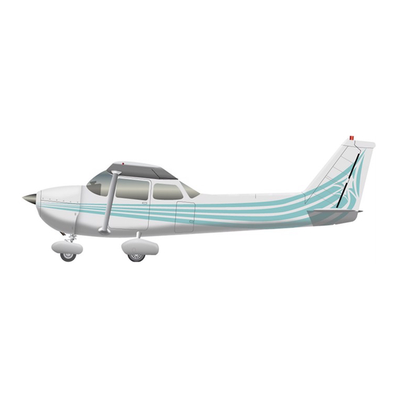
- Page 23 SECTION CESSNA GENERAL MODEL 172R SECTION 1 GENERAL TABLE OF CONTENTS Page Three View - Normal Ground Attitude Introduction Descriptive Data Engine Propeller Fuel Maximum Certificated Weights Standard Airplane Weights Cabin And Entry Dimensions Baggage Space and Entry Dimensions Specific Loadings...
- Page 24 SECTION 1 CESSNA GENERAL MODEL 172R 0510T1005 0510T1005 Three View - Normal Ground Figure 1-1 Attitude (Sheet 1 of 2) Revision...
- Page 25 SECTION CESSNA GENERAL MODEL 172R NOTE 1 : WING SPAN SHOWN WITH STROBE LIGHTS INSTALLED. NOTE 2: WHEEL BASE LENGTH IS 65”. NOTE 3: PROPELLER GROUND CLEARANCE IS 11 1/4”. NOTE 4: WING AREA IS 1 74 SQUARE FEET. NOTE 5:...
-
Page 26: Descriptive Data
This handbook contains 9 sections, and includes the material required to be furnished to the pilot by FAR Part 23. It also contains ■supplemental data supplied by Cessna Aircraft Company. Section 1 provides basic data and information of general interest. also contains... - Page 27 SECTION CESSNA GENERAL MODEL 172R NOTE Isopropyl alcohol or diethylene glycol monomethyl ether (DiEGME) may be added to the fuel supply. Additive exceed 1% for isopropyl alcohol or concentrations shall Refer Section 8 for 0.10% to 0.15% for DiEGME. additional information.
- Page 28 SECTION CESSNA GENERAL MODEL 172R Recommended Viscosity Temperature Range: Temperature MIL-L-6082 MIL-L-22851 or SAE J 1899 SAE J1966 Ashless Dispersant Straight SAE Grade Mineral Oil SAE Grade Above 27°C (80° F) Above 16°C (60°F) -1°C (30°F) 32°C (90°F) -18°C (0°F) to 21 °C (70°F)
- Page 29 SECTION 1 CESSNA GENERAL MODEL 172R Normal Category: Weight in Baggage Compartment, 120 lbs. See note below. Baggage Area 1 (Station 82 to 108): 50 lbs. See below. Baggage Area 2 (Station 108 to 142): note NOTE The maximum combined weight capacity for Baggage Area 1 and Baggage Area 2 is 120 lbs.
- Page 30 SECTION CESSNA GENERAL MODEL 172R SYMBOLS, ABBREVIATIONS AND TERMINOLOGY AIRSPEED TERMINOLOGY AND SYMBOLS GENERAL KCAS Knots Calibrated Airspeed is indicated airspeed corrected for position and instrument error and expressed in knots. Knots calibrated airspeed is equal KTAS in standard atmosphere at sea level.
- Page 31 SECTION 1 CESSNA MODEL 172R GENERAL METEOROLOGICAL TERMINOLOGY Outside Air Temperature is the free air static It may be expressed in either degrees temperature. Celsius or degrees Fahrenheit. Standard Standard Temperature is sea level 5°C at Temperature pressure altitude and decreases by 2°C for each 1 000 feet of altitude.
- Page 32 SECTION CESSNA MODEL 172R GENERAL ENGINE POWER TERMINOLOGY (Continued) Throttle full forward (pushed in, full control travel, Full toward the panel) Also known as "full open" throttle. Throttle Throttle full aft (pulled full control travel, away Closed out, from the panel). Also known as the throttle "idle"...
- Page 33 CESSNA SECTION MODEL 172R GENERAL WEIGHT AND BALANCE TERMINOLOGY Reference Datum is an imaginary vertical plane from Reference Datum which all horizontal distances are measured for balance purposes. Station is a location along the airplane fuselage given Station of the distance from the reference datum.
- Page 34 CESSNA SECTION 1 MODEL 172R GENERAL WEIGHT AND BALANCE TERMINOLOGY (Continued) Center of Gravity Arm is the arm obtained by C.G. individual and dividing adding the airplane's moments sum by the total weight. of Gravity Limits are the extreme center of Center C.G.
- Page 35 CESSNA SECTION 1 MODEL 172R GENERAL IMPERIAL METRIC / / U.S. CONVERSION CHARTS The following charts have been provided help international U.S. supplied with the Pilot’s operators convert measurement Operating Handbook into metric and imperial measurements. The standard followed for measurement units shown, is the...
- Page 36 SECTION 1 CESSNA GENERAL MODEL 172R (Kilograms 2.205 Pounds) (Pounds .454 Kilograms) KILOGRAMS INTO POUNDS KILOGRAMMES EN LIVRES 2.205 4.409 6.614 8.819 11.023 13.228 15.432 17.637 19.842 10 22.046 24.251 26.456 28.660 30.865 33.069 35.274 37.479 39.683 41.888 20 44.093 46.297 48.502 50.706 52.911 55.116 57.320 59.525 61.729 63.934 30 66.139 68.343 70.548 72.753 74.957 77.162 79.366 81.571 83.776 85.980...
- Page 37 CESSNA SECTION MODEL 172R GENERAL (Kilograms 2.205 Pounds) - (Pounds .454 Kilograms) POUNDS KILOGRAMS — d lU — — 190— — 85 180 — — — 75 — — — - — — — — — — - — —...
- Page 38 SECTION 1 CESSNA GENERAL MODEL 172R 3.281 = Feet) (Meters (Feet .305 = Meters) “VI METERS INTO FEET METERES EN PIEDS feet feet feet feet feet feet feet feet feet feet 3.281 9.842 13.123 16.404 19.685 22.956 26.247 29.528 6.562 10 32.808 36.089...
- Page 39 CESSNA SECTION MODEL 172R GENERAL (Meters 3.281 Feet) (Feet .305 Meters) FEET METERS -100 320- 300- 280- 260- 240- 220- 200- 180- 160- 140- 120- 100- Units 10, 100, etc. Figure 1-3 Length Conversions (Sheet 2) Revision 1-17...
- Page 40 CESSNA SECTION 1 MODEL 172R GENERAL Inches) (Inches Centimeters) (Centimeters 2.54 .394 = CENTIMETERS INTO INCHES CENTIMETRES EN POUCES 1.575 1.969 2.362 2.756 3.150 3.543 0.394 0.787 1.181 4.724 5.118 5.512 5.906 6.299 6.693 7.087 7.480 3.937 4.331 9.843 10.236 10.630 11.024 11.417...
- Page 41 CESSNA SECTION 1 MODEL 172R GENERAL (Centimeters Inches) .394 (Inches 2.54 Centimeters) INCHES CENTIMETERS — - 21 - 12 Units 10, 100, etc. 0585T 1 028 Figure 1-4. Length Conversions (Sheet 2) Revision 7 1-19...
- Page 42 CESSNA SECTION 1 MODEL 172R GENERAL (Kilometers x.622=Statute Miles) (Statute Miles x1 .609=Kilometers) (Statute Miles x.869=Nautical Miles) (Nautical Miles x1.15=Statute Miles) (Nautical Miles x1.852=Kilometers) (Kilometers x.54=Nautical Miles) NAUTICAL STATUTE MILES MILES KILOMETERS 100- -180 1 10 -170 90-" -160 85-"...
- Page 43 CESSNA SECTION 1 GENERAL MODEL 172R (Imperial Gallons x 4.546 = Liters) x .22 = Imperial Gallons) (Liters LITERS INTO IMPERIAL GALLONS’ÿ! LITRES EN GALLONS IMPERIAL 1.320 1.540 0.220 0.440 0.660 0.880 1.100 1.760 1.980 2.200 2.420 2.640 2.860 3.080 3.300...
- Page 44 SECTION CESSNA GENERAL MODEL 172R (Imperial Gallons 4.4546 Liters) (Liters Imperial Gallons) 100- IMPERIAL -440 LITERS GALLONS -420 -400 -380 -360 -340 -320 -300 -280 -260 -240 -220 -200 -180 -160 -140 -120 -100 etc. Units 10, 100, 0585T1032 Figure 1-6. Volume Conversions (Sheet 2 of 3)
- Page 45 SECTION 1 CESSNA GENERAL MODEL 172R (Imperial Gallons 1.2 = U.S. Gallons) (U.S. Gallons .833 = imperial Gallons) (U.S. Gallons 3.785 = Liters) .264 = U.S. Gallons) (Liters LTCRS 95--115 95- -360 -110 90- -340 -105 85- -320 85"-100 80- -300 (f®*'...
- Page 46 SECTION 1 CESSNA GENERAL MODEL 172R 0585T1034 Figure Temperature Conversions 1-7. 1-24 Nov 3/97...
- Page 47 SECTION 1 CESSNA MODEL 172R GENERAL PRESSURE CONVERSION HECTOPASCALS (MILLIBARS) TO INCHES MERCURY (inHG) Figure 1-8. Hectopascals Inches Mercury Revision 1-25...
- Page 48 SECTION 1 CESSNA GENERAL MODEL 172R AVGAS Specific Gravity = .72 (Kilograms X 1 .389 (Liters X .72 Kilograms) Liters) (Pounds X .633 = Liters) (Liters X 1 .58 Pounds) LITERS POUNDS KILOGRAMS LITERS 100-i 1-100 135- 95- -150 ISO-'...
- Page 49 CESSNA SECTION 1 GENERAL MODEL 172R Figure 1-1 0. Quick Conversions Revision 7 1-27/1-28...
- Page 53 SECTION 2 CESSNA MODEL 172R LIMITATIONS SECTION 2 LIMITATIONS TABLE OF CONTENTS Page Introduction Airspeed Limitations Airspeed Indicator Markings . . . Powerplant Limitations Powerplant Instrument Markings Weight Limits Normal Category Utility Category Center Of Gravity Limits Normal Category Utility Category...
- Page 55 Section 5. Typel The Cessna Model No. 172R is certificated under FAA Certificate No. 3A12. Revision 4...
-
Page 56: Airspeed Limitations
SECTION 2 CESSNA LIMITATIONS MODEL 172R AIRSPEED LIMITATIONS Airspeed limitations and their operational significance are shown in Figure 2-1 . Maneuvering speeds shown apply normal category operations. The utility maneuvering speed is category 92 KIAS at 2100 pounds. SYMBOL SPEED... -
Page 57: Airspeed Indicator Markings
CESSNA SECTION MODEL 172R LIMITATIONS AIRSPEED INDICATOR MARKINGS Airspeed indicator markings and their color code significance are shown in Figure 2-2. KIAS MARKING VALUE SIGNIFICANCE OR RANGE White Arc 33-85 Full Flap Operating Range. Lower limit is maximum weight landing configuration. Upper limit is maximum speed permissible with flaps extended. -
Page 58: Powerplant Instrument Markings
SECTION CESSNA LIMITATIONS MODEL 172R Fuel Grade: See Fuel Limitations. Oil Grade (Specification): MIL-L-6082 or SAE J1966 Aviation Grade Straight Mineral Oil or MIL-L-22851 or SAE J1899 Ashless Dispersant Oil. Oil must comply with the latest revision and/or supplement for Textron Lycoming Service Instruction No. -
Page 59: Weight Limits
CESSNA SECTION 2 MODEL 172R LIMITATIONS WEIGHT LIMITS NORMAL CATEGORY Maximum Ramp Weight: 2457 lbs. Maximum Takeoff Weight: lbs. 2450 Maximum Landing Weight: 2450 lbs. Maximum Weight in Baggage Compartment: Baggage Area 1 Station 82 to 108:120 lbs. Baggage Area 2 - Station 108 142: 50 lbs. -
Page 60: Maneuver Limits
CESSNA SECTION MODEL 172R LIMITATIONS UTILITY CATEGORY Center of Gravity Range: 35.0 inches aft of datum at 1950 lbs. or less, with Forward: straight line variation 36.5 inches of datum 2100 lbs. inches aft of datum all weights. Aft: 40.5 Reference Datum: Lower portion of front face of firewall. - Page 61 CESSNA SECTION 2 MODEL 172R LIMITATIONS UTILITY CATEGORY This airplane is not designed for purely aerobatic flight. However, in the acquisition of various certificates such as commercial pilot and flight instructor, certain maneuvers are required by the FAA. All of these maneuvers are permitted in this airplane when operated in the utility category.
-
Page 62: Flight Load Factor Limits
CESSNA SECTION 2 MODEL 172R LIMITATIONS FLIGHT LOAD FACTOR LIMITS NORMAL CATEGORY Flight Load Factors (Maximum Takeoff Weight 2450 lbs.): ‘Flaps Up +3.8g, -1 .52g ‘Flaps Down +3.0g ‘The design load factors of the above, and in all 150% the structure meets or exceeds design loads. -
Page 63: Fuel Limitations
CESSNA SECTION MODEL 172R LIMITATIONS FUEL LIMITATIONS Total Fuel: 56 U.S. gallons (2 tanks at 28.0 gallons each). Usable Fuel (all flight conditions): 53.0 U.S. gallons. Unusable Fuel: 3.0 U.S. gallons (1 .5 gallons each tank). NOTE To ensure maximum fuel capacity and minimize cross¬... - Page 64 CESSNA SECTION 2 LIMITATIONS MODEL 172R PLACARDS must be displayed in the form of The following information composite or individual placards. 1. In full view of the pilot: (The "DAY-NIGHT-VFR-IFR" entry, will vary as the airplane is shown on the example below, equipped).
- Page 65 CESSNA SECTION MODEL 172R LIMITATIONS On the fuel selector valve: TAKEOFF BOTH ALL FLIGHT LANDING 53.0 GAL. ATTITUDES FUEL SELECTOR LEFT RIGHT 26.5 GAL. 26.5 GAL. LEVEL LEVEL FLIGHT FLIGHT ONLY ONLY Near fuel tank filler cap: FUEL 100LU MIN. GRADE AVIATION GASOLINE CAP.
- Page 66 SECTION 2 CESSNA LIMITATIONS MODEL 172R In baggage compartment: 120 POUNDS MAXIMUM BAGGAGE FORWARD OF BAGGAGE DOOR LATCH 50 POUNDS MAXIMUM BAGGAGE AFT OF BAGGAGE DOOR LATCH MAXIMUM 120 POUNDS COMBINED FOR ADDITIONAL LOADING INSTRUCTIONS SEE WEIGHT AND BALANCE DATA...
- Page 67 CESSNA SECTION MODEL 172R LIMITATIONS On the Upper Right Side the Aft Cabin Partition: EMERGENCY LOCATOR TRANSMITTER INSTALLED AFT OF THIS PARTITION MUST BE SERVICED IN ACCORDANCE WITH FAR PART 91 .207 On forward face of firewall adjacent the battery: CAUTION 24 VOLTS D.C.
- Page 71 SECTION 3 CESSNA EMERGENCY PROCEDURES MODEL 172R SECTION 3 EMERGENCY PROCEDURES TABLE OF CONTENTS Page Introduction AIRSPEEDS Airspeeds For Emergency Operation EMERGENCY PROCEDURES CHECKLIST Engine Failures Engine Failure During Takeoff Roll Engine Failure Immediately After Takeoff Engine Failure During Flight (Restart Procedures)
- Page 72 CESSNA SECTION 3 MODEL 172R EMERGENCY PROCEDURES TABLE OF CONTENTS (Continued) Page Electrical Power Supply System Malfunctions 3-11 Ammeter Shows Excessive Rate of Charge (Full Scale Deflection) 3-11 Low Voltage Annunciator (VOLTS) Illuminates During Flight Indicates Discharge) 3-11 (Ammeter Vacuum System Failure...
- Page 73 CESSNA SECTION 3 MODEL 172R EMERGENCY PROCEDURES INTRODUCTION Section 3 provides checklist and amplified procedures for coping with emergencies that may occur. Emergencies caused by airplane or engine malfunctions are proper extremely rare if preflight inspections and maintenance are practiced. Enroute weather...
-
Page 74: Emergency Procedures Checklist
SECTION 3 CESSNA EMERGENCY PROCEDURES MODEL 172R EMERGENCY PROCEDURES CHECKLIST Procedures in the Emergency Procedures Checklist portion of are immediate action items this section shown in bold faced type committed which should be memory. ENGINE FAILURES ENGINE FAILURE DURING TAKEOFF ROLL Throttle IDLE. - Page 75 CESSNA SECTION 3 MODEL 172R EMERGENCY PROCEDURES ENGINE FAILURE DURING FLIGHT (Restart Procedures) 1. Airspeed 65 KIAS. 2. Fuel Shutoff Valve ON (push full in). 3. Fuel Selector Valve BOTH. 4. Auxiliary Fuel Pump Switch 5. Mixture RICH (if restart has not occurred).
- Page 76 SECTION 3 CESSNA EMERGENCY PROCEDURES MODEL 172R PRECAUTIONARY LANDING WITH ENGINE POWER 1 . Passenger Seat Backs MOST UPRIGHT POSITION. and Seat Belts SECURE. 2. Seats 3. Airspeed 60 KIAS. 4. Wing Flaps 20°. 5. Selected Field FLY OVER, noting terrain and obstructions, then retract flaps upon reaching a safe altitude and airspeed.
- Page 77 SECTION 3 CESSNA MODEL 172R EMERGENCY PROCEDURES FIRES DURING START ON GROUND Ignition Switch START, Continue Cranking to get a start which would suck the flames and accumulated fuel into the engine. If engine starts: Power 1700 RPM for a few minutes.
- Page 78 SECTION 3 CESSNA EMERGENCY PROCEDURES MODEL 172R ELECTRICAL FIRE IN FLIGHT 1. Master Switch OFF. Cabin Air, Heat - CLOSED. 2. Vents, Fire Extinguisher ACTIVATE (if available). 4. Avionics Master Switch OFF. 5. All Other Switches (except ignition switch) OFF.
- Page 79 SECTION 3 CESSNA EMERGENCY PROCEDURES MODEL 172R WING FIRE Landing/Taxi Light Switches OFF. 2. Navigation Light Switch OFF. OFF. 3. Strobe Light Switch OFF. 4. Pitot Heat Switch NOTE flames away from the fuel Perform a sideslip to keep the tank and cabin.
- Page 80 SECTION 3 CESSNA EMERGENCY PROCEDURES MODEL 172R 10. Approach at 65 to 75 KIAS depending upon the of the amount accumulation. Perform a landing level attitude. STATIC SOURCE BLOCKAGE Instrument Reading Suspected) (Erroneous Static Pressure Alternate Source Valve PULL ON.
- Page 81 SECTION 3 CESSNA EMERGENCY PROCEDURES MODEL 172R ELECTRICAL POWER SUPPLY SYSTEM MALFUNCTIONS AMMETER SHOWS EXCESSIVE RATE OF CHARGE (Full Scale Deflection) Alternator OFF. CAUTION WITH THE ALTERNATOR SIDE OF THE MASTER SWITCH OFF, COMPASS DEVIATIONS OF AS MUCH AS 25° MAY OCCUR.
- Page 82 SECTION 3 CESSNA EMERGENCY PROCEDURES MODEL 172R VACUUM SYSTEM FAILURE ILeft Vacuum (L VAC) Annunciator or Right Vacuum (VAC R) |Annunciator Illuminates. CAUTION VACUUM WITHIN NORMAL FAILURE OPERATING LIMITS, OCCURRED IN THE VACUUM SYSTEM AND PANEL PROCEDURES PARTIAL REQUIRED FOR CONTINUED FLIGHT.
- Page 83 CESSNA SECTION 3 MODEL 172R EMERGENCY PROCEDURES AMPLIFIED EMERGENCY PROCEDURES The following Amplified Emergency Procedures elaborate upon information contained in the Emergency Procedures Checklists portion of this section. These procedures also include information not readily adaptable a checklist format, and...
- Page 84 SECTION 3 CESSNA EMERGENCY PROCEDURES MODEL 1 72R After an engine failure in flight, the most important course of action is to continue flying the airplane. Best glide speed as shown in Figure 3-1 should be established as quickly as possible. While...
-
Page 85: Landing Without Elevator Control
CESSNA SECTION 3 MODEL 172R EMERGENCY PROCEDURES FORCED LANDINGS If all attempts to restart the engine fail and a forced landing is imminent, select a suitable field and prepare for the landing as discussed under the Emergency Landing Without Engine Power checklist. - Page 86 CESSNA SECTION 3 EMERGENCY PROCEDURES MODEL 172R At the landing flare (round-out), the nose down moment resulting power reduction is an adverse factor and the airplane may land from on the nose wheel. Consequently, at flare, the elevator trim control...
- Page 87 CESSNA SECTION 3 MODEL 172R EMERGENCY PROCEDURES accuracy of the turn by observing the compass 3. Check heading which should be the reciprocal of the original heading. necessary, adjust heading primarily with skidding motions 4. If rather than rolling motions so that the compass will read more accurately.
- Page 88 SECTION 3 CESSNA EMERGENCY PROCEDURES MODEL 172R RECOVERY FROM SPIRAL DIVE IN THE CLOUDS is encountered in the clouds, proceed as follows: If a spiral Retard throttle to idle position. Stop the turn by using coordinated aileron and rudder control...
- Page 89 SECTION 3 CESSNA EMERGENCY PROCEDURES MODEL 172R When using the alternate static source, refer to the Alternate Stat¬ ic Source Airspeed Calibration table in Section 5, Performance, for additional information. Maximum airspeed and altimeter variation from normal is 4 knots and 30 feet over the normal operating range with the window(s) closed.
- Page 90 SECTION 3 CESSNA EMERGENCY PROCEDURES MODEL 172R ROUGH ENGINE OPERATION OR LOSS OF POWER SPARK PLUG FOULING A slight engine roughness in flight may be caused by one or more spark plugs becoming fouled by carbon or lead deposits. This may be verified by turning the ignition switch momentarily from or R position.
- Page 91 Temporary Revision for Cessna Pilot's Operating Handbook and FAA Approved Airplane Flight Manual Publication Affected: Model 172R (172RPHUS09), 172R180 (172R180PHUS03), 172S (172SPHUS05) Pilot's Operating Handbook and FAA Approved Airplane Flight Manual. Serial Numbers Affected: Airplanes 17280001 172S8001 and On not incorporating the Nav III Avionics Option (G1000).
- Page 92 Revision for Cessna Pilot's Operating Handbook and Temporary FAA Approved Airplane Flight Manual APPROVED BY fWT21 8WWT U CFR HJJfTKNE) UNDER CMmNaatCo. Autnrtnfeft DOWSOS»«E Opfan oo»w*»rjJÿ DATE OF APPROVAL 172PHTR02...
- Page 93 CESSNA SECTION MODEL 172R EMERGENCY PROCEDURES EXCESSIVE FUEL VAPOR INDICATIONS Excessive fuel vapor is most likely generated during ground operations when operating higher altitudes, in unusually warm temperatures or with more volatile fuel blends. Operation or near idle RPM (low fuel flow) for extended periods will increase the chances of fuel vapor generation.
- Page 94 CESSNA SECTION 3 MODEL 172R EMERGENCY PROCEDURES ELECTRICAL POWER SUPPLY SYSTEM MALFUNCTIONS Malfunctions in the electrical power supply system can be by periodic monitoring of the ammeter and low voltage detected lannunciator cause of these malfunctions is (VOLTS); however, the usually difficult to determine.
-
Page 95: Other Emergencies
SECTION 3 CESSNA MODEL 172R EMERGENCY PROCEDURES INSUFFICIENT RATE OF CHARGE NOTE The low voltage annunciator (VOLTS) may come on and indications ammeter discharge may occur during low RPM conditions with an electrical load on the such as system, a low RPM taxi. Under these conditions, the during ■... - Page 99 SECTION CESSNA NORMAL PROCEDURES MODEL 172R SECTION 4 NORMAL PROCEDURES TABLE OF CONTENTS Page Introduction AIRSPEEDS Airspeeds For Normal Operation CHECKLIST PROCEDURES Preflight Inspection Cabin Empennage Right Wing, Trailing Edge Right Wing rNose Left Wing 4-10 Left Wing, Leading Edge...
- Page 100 SECTION CESSNA NORMAL PROCEDURES MODEL 172R TABLE OF CONTENTS (Continued) Landing 4-17 4-17 Normal Landing 4-17 Short Field Landing Balked Landing 4-17 4-17 After Landing 4-17 Airplane Securing AMPLIFIED PROCEDURES 4-18 Inspection Preflight 4-19 Starting Engine 4-20 Duty Cycle Recommended Starter...
- Page 101 SECTION CESSNA NORMAL PROCEDURES MODEL 172R TABLE OF CONTENTS (Continued) Page Landing 4-32 Normal Landing 4-32 Short Field Landing 4-33 Crosswind Landing 4-33 Balked Landing 4-33 Cold Weather Operation 4-34 Winterization Kit 4-35 Hot Weather Operation 4-36 Noise Characteristics And Noise Reduction...
- Page 103 SECTION CESSNA PROCEDURES NORMAL MODEL 172R INTRODUCTION provides checklist and amplified procedures for the Section conduct of normal operation. Normal procedures associated with optional systems can be found in the Supplements, Section 9. AIRSPEEDS AIRSPEEDS FOR NORMAL OPERATION Unless otherwise noted, the following speeds are based on a maximum weight of 2450 pounds and may be used for any lesser weight.
- Page 104 SECTION CESSNA NORMAL PROCEDURES MODEL 1 72R NOTE Visually check airplane for general condition during walk- around inspection. Airplane should be parked in a normal ensure that fuel ground attitude (refer Figure 1-1) to accurate sampling. Use of the drain valves allow for...
- Page 105 SECTION CESSNA PROCEDURES NORMAL MODEL 172R CHECKLIST PROCEDURES PREFLIGHT INSPECTION © CABIN REMOVE. Check for pitot blockage. Pitot Tube Cover Pilot's Operating Handbook AVAILABLE IN THE AIRPLANE. 3. Airplane Weight and Balance CHECKED. 4. Parking Brake SET. 5. Control Wheel Lock -- REMOVE.
- Page 106 SECTION 4 CESSNA NORMAL PROCEDURES MODEL 172R Annunciator Panel Test Switch RELEASE. Check that appropriate annunciators remain on. NOTE When Master Switch is turned some annunciators will flash for approximately 10 seconds before illuminating steadily. When panel TST switch is toggled...
- Page 107 SECTION 4 CESSNA PROCEDURES NORMAL MODEL 172R Main Wheel Tire -- CHECK for proper inflation and general wear, etc...). condition (weather checks, tread depth and DRAIN at least a Fuel Tank Sump Quick Drain Valves cupful of fuel (using sampler cup) from each sump...
- Page 108 SECTION CESSNA NORMAL PROCEDURES MODEL 172R 2. Engine Oil Dipstick/Filler Cap CHECK oil level, then check dipstick/filler cap SECURE. Do operate with less than five quarts. Fill to eight for extended flight. quarts 3. Engine Cooling Air Inlets -- CLEAR of obstructions.
-
Page 109: Before Starting Engine
SECTION CESSNA NORMAL PROCEDURES MODEL 172R © LEFT WING Leading Edge Fuel Tank Vent Opening CHECK for blockage. Stall Warning Opening CHECK for blockage. To check the over the place a clean handkerchief vent opening and system, apply suction; a sound from the warning horn will confirm system operation. - Page 110 SECTION CESSNA NORMAL PROCEDURES MODEL 172R STARTING ENGINE (With Battery) Throttle OPEN INCH. 2. Mixture - IDLE CUTOFF. 3. Propeller Area CLEAR. 4. Master Switch 5. Flashing Beacon NOTE 6, 7, If engine is warm, omit priming procedure of steps 8 below.
- Page 111 Temporary Revision for Cessna Pilot’s Operating Handbook and FAA Approved Airplane Flight Manual Publication Affected: Model 172R. 172R180, and 172S Pilot’s Operating Handbook and FAA Approved Airplane Flight Manual. Serial Numbers Affected: Airplanes incorporating SB04-24-01. Description of Change: New Starting Engine Procedure.
- Page 113 Revision lor Cessna Pilot's Operating Handbook and Temporary Approved Airplane Flight Manual STARTING ENGINE (Continued) NOTE If engine floods has been primed much), (engine verify auxiliary fuel pump mixture idle off, to full, and motor (crank) cutoff, open throttle 1/2 engine.
- Page 115 SECTION CESSNA NORMAL PROCEDURES MODEL 172R External Power) STARTING ENGINE (With OPEN 1/4 INCH. 1. Throttle Mixture IDLE CUTOFF. 3. Propeller Area CLEAR. Switch OFF. 4. Master 5. External Power CONNECT airplane receptacle. 6. Master Switch 7. Flashing Beacon NOTE...
- Page 116 SECTION CESSNA NORMAL PROCEDURES MODEL 172R b. Taxi and Landing Light Switches provide an initial electrical load on the system). c. Engine RPM REDUCE to idle. (Minimum alternator output occurs at idle.) ON (with taxi and landing lights switched d. Master Switch on).
- Page 117 Page 4-15, BEFORE Section 4, Normal Procedures, Description of Change: TAKEOFF, revise Steps 12 and 13. Insert this temporary revision in the Model 172R Instructions: Filing Serials 17280001 and On basic Pilot’s Nav l/Nav Operating Handbook and FAA Approved Airplane Flight Manual adjacent to page 4-14.
- Page 119 TEMPORARY REVISION FOR CESSNA PILOT’S OPERATING HANDBOOK AND FAA APPROVED AIRPLANE FLIGHT MANUAL BEFORE TAKEOFF Throttle Control CHECK IDLE Throttle Control 1000 RPM or LESS 172RPHUS-09 TR03...
- Page 121 SECTION CESSNA NORMAL PROCEDURES MODEL 172R BEFORE TAKEOFF 1 . Parking Brake SET. Passenger Seat Backs MOST UPRIGHT POSITION. 3. Seats and Seat Belts CHECK SECURE. 4. Cabin Doors CLOSED and LOCKED. 5. Flight Controls -- FREE and CORRECT. 6. Flight Instruments CHECK and SET.
- Page 122 SECTION CESSNA NORMAL PROCEDURES MODEL 172R SHORT FIELD TAKEOFF Wing Flaps 1 0°. 2. Brakes APPLY. Throttle FULL OPEN. LEAN obtain maximum Mixture RICH (above 3000 feet, RPM). 5. Brakes RELEASE. Elevator Control SLIGHTLY TAIL LOW. 7. Climb Speed 57 KIAS (until all obstacles cleared).
- Page 123 SECTION 4 CESSNA NORMAL PROCEDURES MODEL 172R BEFORE TAKEOFF Parking Brake -- SET. Passenger Seat Backs MOST UPRIGHT POSITION. 3. Seats and Seat Belts -- CHECK SECURE. 4. Cabin Doors CLOSED and LOCKED. 5. Flight Controls FREE and CORRECT. 6. Flight Instruments CHECK and SET.
- Page 124 SECTION CESSNA NORMAL PROCEDURES MODEL 172R SHORT FIELD TAKEOFF 1. Wing Flaps --10°. 2. Brakes APPLY. Throttle FULL OPEN. 4. Mixture RICH (above 3000 feet, LEAN obtain maximum RPM). 5. Brakes RELEASE. 6. Elevator Control SLIGHTLY TAIL LOW. 57 KIAS (until all obstacles are cleared).
-
Page 125: After Landing
SECTION 4 CESSNA NORMAL PROCEDURES MODEL 172R LANDING NORMAL LANDING Airspeed 65-75 KIAS (flaps UP). Wing Flaps -- AS DESIRED (0°-10° below 110 KIAS, 10°-30° below 85 KIAS). 60-70 KIAS (flaps DOWN). 3. Airspeed Touchdown - MAIN WHEELS FIRST. 5. Landing Roll LOWER NOSE WHEEL GENTLY. - Page 126 SECTION 4 CESSNA NORMAL PROCEDURES MODEL 172R AMPLIFIED PROCEDURES PREFLIGHT INSPECTION The Preflight Inspection, described in Figure 4-1 and adjacent checklist, is required prior to each flight. If airplane has been in extended storage, has had major maintenance, or has been...
- Page 127 SECTION CESSNA NORMAL PROCEDURES MODEL 172R or in snow or If the airplane has been operated from muddy fields obstructions slush, check the main and nose gear wheel fairings for a gravel or cinder field will require and cleanliness. Operation from...
- Page 128 SECTION CESSNA NORMAL PROCEDURES MODEL 172R Should the engine tend die after starting, on the auxiliary turn fuel pump temporarily and adjust the throttle and/or mixture as necessary the engine running. In the event of over to keep priming flooding, turn off the auxiliary fuel pump, open the throttle from 1/2 to full open, and continue cranking with the mixture full lean.
- Page 129 SECTION 4 CESSNA PROCEDURES NORMAL MODEL 172R LEANING FOR GROUND OPERATIONS For all ground operations, after starting the engine and when the engine is running smoothly: the throttle to 1 200 RPM. b. lean the mixture for maximum RPM. an RPM appropriate for...
- Page 130 SECTION CESSNA NORMAL PROCEDURES MODEL 172R jflM liiiiiiiisx lUSE lUSE UP AILERON UP AILERON WING AND NEUTRAL ELEVATOR CODE WIND DIRECTION NOTE tail winds require caution. Strong quartering and sharp the throttle Avoid sudden bursts of braking when the airplane is in this situation.
- Page 131 HANDBOOK TEMPORARY REVISION FOR CESSNA PILOT’S OPERATING AND FAA APPROVED AIRPLANE FLIGHT MANUAL Model 172R Nav I/ll Serials 17280001 and On, Publication Affected: Handbook basic Pilot's Operating Manual, Revision dated Approved Airplane Flight 19 July 2004. Airplanes 17280001 thru 17281356 equipped with Airplane Serial Numbers Affected: Nav l/Nav II avionics option.
- Page 133 TEMPORARY REVISION FOR CESSNA PILOT'S OPERATING HANDBOOK AND FAA APPROVED AIRPLANE FLIGHT MANUAL BEFORE TAKEOFF WARM UP If the engine idles smoothly with the throttle against the idle stop, (approximately 675 RPM) and accelerates smoothly, the engine is ready for takeoff.
- Page 135 SECTION 4 CESSNA NORMAL PROCEDURES MODEL 172R BEFORE TAKEOFF WARM UP If the engine idles (approximately 600 RPM) and accelerates smoothly, the airplane is ready for takeoff. Since the engine is closely cowled for efficient in-flight engine cooling, precautions should be taken avoid overheating during prolonged engine operation on the ground.
- Page 136 SECTION 4 CESSNA NORMAL PROCEDURES MODEL 172R LANDING LIGHTS If landing lights be used enhance the visibility of the airplane in the traffic it is recommended that only pattern enroute, the taxi light be used. This will extend the service life of the landing light appreciably.
- Page 137 CESSNA SECTION 4 MODEL 172R NORMAL PROCEDURES WING FLAP SETTINGS Normal takeoffs are accomplished with wing flaps 0°-10°. Using 10° wing flaps reduces the ground roll and total distance over an obstacle by approximately 10 percent. Flap deflections greater than 10° are not approved for takeoff. If 10° wing flaps are used...
- Page 138 The Cruise Performance charts in Section 5 provide the pilot with detailed information concerning the cruise performance of the Model 172R in still air. Power and altitude, as well as winds aloft, have a influence on the time and fuel needed to complete any flight.
- Page 139 CESSNA SECTION 4 MODEL 172R NORMAL PROCEDURES POWER POWER POWER ALTITUDE KTAS NMPG KTAS NMPG KTAS NMPG Sea Level 12.3 13.4 14.5 4000 feet 12.8 13.9 14.9 8000 feet 13.3 14.3 15.3 Figure 4-3. Cruise Performance Table LEANING USING THE EGT INDICATOR...
- Page 140 CESSNA SECTION 4 MODEL 172R NORMAL PROCEDURES NOTE The EGT indicator requires several seconds to respond mixture adjustments and changes in exhaust gas temperature. More rapid changes in nor desirable. EGT indication are neither necessary Determining peak EGT and setting the desired...
- Page 141 SECTION CESSNA PROCEDURES NORMAL MODEL 172R FUEL VAPOR PROCEDURES vapor become susceptible to fuel The engine fuel system formation on the ground during warm weather. This will generally 80°F.| occur outside ambient air temperature is above when the The situation is further aggravated by the fact that the engine fuel speeds.
- Page 142 Cessna 172R. The cabin should be clean and all loose equipment (including the microphone and rear seat belts) should be stowed or secured. For a...
- Page 143 CESSNA SECTION MODEL 172R NORMAL PROCEDURES The normal entry is made from a power off stall. As the stall approached, the elevator control should be smoothly pulled to the full aft position. Just prior to reaching the stall "break", rudder...
- Page 144 SECTION 4 CESSNA NORMAL PROCEDURES MODEL 172R NOTE a visual determination of the If disorientation precludes direction of rotation, the symbolic airplane in the turn coordinator may be referred for this information. Variations in basic airplane rigging or in weight and balance due...
- Page 145 SECTION CESSNA NORMAL PROCEDURES MODEL 172R SHORT FIELD LANDING For a short field landing in smooth air conditions, make power approach at 62 KIAS with 30° flaps using enough to control should be used the glide path. (Slightly higher approach speeds under turbulent air conditions.) After all approach obstacles are...
-
Page 146: Cold Weather Operation
SECTION 4 CESSNA NORMAL PROCEDURES MODEL 172R COLD WEATHER OPERATION consideration should be given to the operation of the Special or prior airplane fuel system during the winter season to any flight cold temperatures. Proper preflight draining of the fuel system especially important and will eliminate any free water accumulation. - Page 147 CESSNA SECTION 4 MODEL 172R NORMAL PROCEDURES When using an external power source, the master switch must be the OFF position before connecting the external power source to the airplane receptacle. See Section 7, Ground Service Plug Receptacle for external power source operations.
-
Page 148: Hot Weather Operation
NOISE CHARACTERISTICS AND NOISE REDUCTION The certificated noise level for the Model 172R at 2450 pounds maximum weight is 73.3 dB(A). No determination has been made by the Federal Aviation Administration that the noise levels of this are or should be acceptable or unacceptable... - Page 149 rcnruntnHHbc...
- Page 150 PERFORMANCE...
- Page 151 CESSNA SECTION 5 MODEL 172R PERFORMANCE SECTION 5 PERFORMANCE TABLE OF CONTENTS Page Introduction Use of Performance Charts Sample Problem Takeoff Cruise Fuel Required Landing Demonstrated Operating Temperature Figure 5-1, Airspeed Calibration Normal Static Source Airspeed Calibration Alternate Static Source...
-
Page 153: Sample Problem
CESSNA SECTION 5 MODEL 172R PERFORMANCE INTRODUCTION Performance data charts on the following pages are presented so that you may know what to expect from the airplane under various conditions, and also, to facilitate the planning of flights in detail and with reasonable accuracy. - Page 154 SECTION CESSNA PERFORMANCE MODEL 172R CRUISE CONDITIONS: Total distance 320 Nautical Miles Pressure altitude 5500 Feet Temperature 20° Expected wind 10 Knot Headwind enroute LANDING CONDITIONS: Field pressure altitude 2000 Feet Temperature 25°C Field length 3000 Feet TAKEOFF The takeoff distance chart, Figure 5-5, should be consulted, keeping in mind that distances shown are based on the short field technique.
- Page 155 CESSNA SECTION 5 MODEL PERFORMANCE 172R clear a Total distance 50-foot obstacle, zero wind 2290 Decrease in total distance (2290 feet X 13%) -298 Corrected total distance clear 50-foot obstacle 1 992 Feet CRUISE The cruising altitude should be selected based on a consideration of trip length, winds aloft, and the airplane's performance.
- Page 156 SECTION 5 CESSNA PERFORMANCE MODEL 172R FUEL REQUIRED The total fuel requirement for the flight may be estimated using the performance information in Figure 5-7 and Figure For this 5-8. sample problem, Figure 5-7 shows that a climb from 2000 feet 6000 feet requires 1 .4 gallons of fuel.
- Page 157 SECTION CESSNA MODEL 172R PERFORMANCE The resultant cruise distance is: Total distance Climb distance Cruise distance With an expected 10 knot headwind, the ground speed for cruise is predicted to be: 99 Knots Therefore, the time required for the cruise portion of the trip is: 308 Nautical Miles = 3.1 Hours...
-
Page 158: Demonstrated Operating Temperature
SECTION CESSNA PERFORMANCE MODEL 172R LANDING A procedure similar takeoff should be used for estimating the landing distance destination airport. Figure 5-11 presents at the landing distance information for field technique. The the short feet and 30 °C are as follows:... -
Page 159: Airspeed Calibration
CESSNA SECTION MODEL 172R PERFORMANCE AIRSPEED CALIBRATION NORMAL STATIC SOURCE CONDITION: Power required for level flight or maximum rated RPM dive. FLAPS KIAS 50 60 70 80 90 100 110 120 130 140 150 160 KCAS 56 62 70 79 89 98 107 117 126 135 145 154 FLAPS 10°... - Page 160 CESSNA SECTION PERFORMANCE MODEL 172R AIRSPEED CALIBRATION ALTERNATE STATIC SOURCE HEATER AND WINDOWS CLOSED OFF, VENTS FLAPS UP NORMAL KIAS ALTERNATE KIAS FLAPS 10° 90 100 110 NORMAL KIAS 99 108 ALTERNATE KIAS 40 FLAPS 30° NORMAL KIAS ALTERNATE KIAS 38...
- Page 161 CESSNA SECTION MODEL 172R PERFORMANCE F A H R E N H E I T D E G R E E S DEGREES CELSIUS Figure 5-2. Temperature Conversion Chart Dec 2/96 5-11...
- Page 162 CESSNA SECTION 5 MODEL 172R PERFORMANCE STALL SPEEDS AT 2450 POUNDS Conditions: Power Off MOST REARWARD CENTER OF GRAVITY ANGLE OF BANK FLAP 30° 45° 60° SETTING KIAS KCAS KIAS KCAS KIAS KCAS KIAS KCAS 10° 30° MOST FORWARD CENTER OF GRAVITY...
-
Page 163: Wind Components
CESSNA SECTION 5 MODEL 172R PERFORMANCE WIND COMPONENTS NOTE Maximum demonstrated crosswind velocity is knots (not limitation). NOTE Maximum demonstrated crosswind component is 15 knots (not a limitation). 0585C1003 Figure 5-4. Crosswind Components Revision 7 5-13... - Page 164 SECTION 5 CESSNA PERFORMANCE MODEL 172R SHORT FIELD TAKEOFF DISTANCE AT 2450 POUNDS CONDITIONS: Flaps 10° Full Throttle Prior Brake Release Paved, level, dry runway Zero Wind Lift Off: 51 KIAS Speed Ft: 57 KIAS at 50 o°c 1( )°C 20°C...
- Page 165 CESSNA SECTION MODEL 172R PERFORMANCE MAXIMUM RATE-OF-CLIMB AT 2450 POUNDS CONDITIONS: Flaps Up Full Throttle PRESS CLIMB RATE OF CLIMB A 1 T CDCcrt ML 1 jrCCL/ -20°C o°c KIAS 20°C 40°C S.L. 2000 4000 6000 8000 10,000 12,000 NOTE: 1.
- Page 166 CESSNA SECTION MODEL 172R PERFORMANCE TIME, FUEL AND DISTANCE TO CLIMB AT 2450 POUNDS CONDITIONS: Flaps Up Full Throttle Standard Temperature FROM SEA LEVEL RATE PRESS CLIMB TEMP FUEL TIME SPEED DIST CLIMB °C USED KIAS S.L. 1000 2000 3000...
-
Page 167: Cruise Performance
CESSNA SECTION 5 MODEL 172R PERFORMANCE CRUISE PERFORMANCE CONDITIONS: 2450 Pounds Recommended Lean Mixture At All Altitudes (Refer to Section Cruise) 20°C STANDARD 20°C ABOVE BELOW PRESS STANDARD TEMP TEMPERATURE STANDARD TEMP BHP KTAS GPH BHP KTAS GPH BHP KTAS GPH —... - Page 168 SECTION CESSNA PERFORMANCE MODEL 172R CRUISE PERFORMANCE CONDITIONS: 2450 Pounds Recommended Lean Mixture At All Altitudes (Refer to Section 4, Cruise) 20°C BELOW STANDARD 20°C ABOVE PRESS TEMP STANDARD TEMPERATURE STANDARD TEMP BHP KTAS GPH BHP KTAS GPH KTAS GPH...
- Page 169 CESSNA SECTION MODEL 172R PERFORMANCE RANGE PROFILE 45 MINUTES RESERVE 53 GALLONS USABLE FUEL CONDITIONS: Pounds 2450 Recommended Lean Mixture for Cruise At All Altitudes Standard Temperature Zero Wind RANGE - NAUTICAL MILES NOTES: 1. This chart allows for the fuel used for engine...
- Page 170 SECTION CESSNA PERFORMANCE MODEL 172R ENDURANCE PROFILE 45 MINUTES RESERVE GALLONS USABLE FUEL CONDITIONS: 2450 Pounds Recommended Lean Mixture for Cruise At All Altitudes Standard Temperature NOTE: This chart allows the fuel used for engine start, taxi, takeoff climb, and the time during climb.
- Page 171 CESSNA SECTION 5 MODEL 172R PERFORMANCE SHORT FIELD LANDING DISTANCE AT 2450 POUNDS CONDITIONS: Flaps 30° Power Off Maximum Braking Paved, level, dry runway Zero Wind Speed at 50 62 KIAS o°c 10°C 20°C 30°C 40°C Grnd Grnd Total Total...
- Page 173 SECTION 5 CESSNA PERFORMANCE MODEL 172R SHORT FIELD LANDING DISTANCE AT 2450 POUNDS CONDITIONS: Flaps 30° Power Off Maximum Braking Paved, level, dry runway Zero Wind KIAS Speed at 50 Ft: 62 40°C o°c 10°C 20°C 30°C Total Grnd Total Grnd Total Grnd Total...
- Page 177 CESSNA SECTION 6 MODEL 172R WEIGHT & BALANCE/EQUIPMENT LIST SECTION 6 WEIGHT & BALANCE/ EQUIPMENT LIST TABLE OF CONTENTS Page Introduction Airplane Weighing Procedures JWN Weight And Balance Baggage Tie-Down 6-17 Comprehensive Equipment List Revision 6- 1/6-2...
-
Page 179: Airplane Weighing Procedures
Procedures for calculating the weight and for various operations are also provided. A comprehensive moment list of all Cessna equipment available for this airplane is included the back of this section. It should be noted that specific information regarding the weight,... - Page 180 CESSNA SECTION 6 MODEL 172R WEIGHT BALANCE / EQUIPMENT LIST & AIRPLANE WEIGHING FORM REFERENCE DATUM (FIREWALL FRONT FACE, •NOTE- LOWER PORTION) STA 0.0 IT IS THE RESPONSIBILITY OF THE PILOT TO ENSURE THAT THE AIRPLANE IS LOADED PROPERLY. 150-...
- Page 181 CESSNA SECTION 6 MODEL 172R WEIGHT BALANCE EQUIPMENT LIST & LOCATING CG WITH AIRPLANE ON LANDING GEAR FORMULA for Longitudinal CG: (NOSE GEAR NET WEIGHT) ) X (B) INCHES (A)- AFT OF NOSE AND MAIN LANDING GEAR WEIGHT DATUM TOTALED (...
-
Page 182: Weight And Balance
CESSNA SECTION 6 MODEL 172R / EQUIPMENT LIST WEIGHT & BALANCE 3. Weighing: errors caused a. Weigh airplane in a closed hangar to avoid currents. level and brakes released, record the b. With the airplane weight shown on each scale. Deduct the... - Page 183 783BG 168,2 40.2*1 Moment 6/647.21 Gross Weight 2450 Useful Load *NOTE* This is NOT an official Weight and Balance for ,ÿhii For the actual weight and balance, please refer the Weight ■ ■. ecUal -r ’ For tbs form in this POH *NOTE* All weights are in pounds...
- Page 185 140 NORTH AIRPORT DRIVE, H4NR191N KIMBALL, Ml 48074 Tel: 810-364-2722 A/C Tail#: N783BG CESSNA A/C Make Register Name : BOWLING GREEN FLIGHT CENTER LLC 172R A/C Model Name 2 A/C Serial # 17281021 905 E POE RD Address 1 2762...
- Page 187 (410)888-9050 (419) 866-9047 SUPPLEMENTAL EQUIPMENT LIST and/or WEIGHT AND BALANCE DATA AIRCRAFT MAKE: CESSNA DATE: 12-Mar-07 AIRCRAFT MODEL 172R REGISTRATION N783BG SERIAL NUMBER 17281021 REGISTERED OWNER BOWLING GREEN UNIVERSITY TECHNOLOGY ANNEX BOWLING GREEN. OH 43403 STARTING WEIGHT AND BALANCE DATA...
- Page 189 rVr\ rluni 0 IC'-J uwill|nuu ..ICIICI.U5AI IIMIUhv kilKUA "H.l I'lHill'K »-.»< IIV1.M USOl -CUT HERE BALANCE/EQUIPMENT LIST REVISION WEIGHT Sky-Tec Sorinl Beginning _ _ _ _ _ DATE: NAME: MODEL AIRCRAFT MAKE/TYPE: Lycoming »: »: fr 3 <3 SERIAL REGISTRATION lbs.
- Page 190 Form Tracking Number Approving Nation Avaition Authority AUTHORIZED RELEASE CERTIFICATE /Country FN-370519 AIRWORTHINESS APPROVAL TAG FAA Form 8130-3 FAA/United States 5. Work Order/Contract/ 4. Ogranization Name and Address Invoice Number Sky-Tec 350 Howard Clemmons Granbury, Texas 76048 (PQ0852SW) FN-370519 10. Quanity 6.
- Page 191 WEIGHT AND BALANCE SUPPLIMENTAL EQUIPMENT LIST MAKE AND MODEL: Cessna 172R REGISTRATION NO. : N783BG OWNER: Flight Management, LLC SERIAL NO. 17281021 Item Description Weight Moment Old Weight 1701.1 40.26 68480.61 Dated 12-19-01 Equipment Removed -16.5 46.1 -760.6 Cessna Item:...
- Page 192 • » •...
- Page 193 Tel. (419) « FAX: (419) < SUPPLEMENTAL EQUIPMENT LIST and/oc WEIGHT AND BALANCE DATA AIRCRAFT MAKE: CESSNA DATE: 19-Dec-Ol AIRCRAFT MODEL: 172R «: REGISTRATION N24730 SERIAL NUMBER; 17281021 REGISTERED OWNER: FLIGHTMANAGEMENT BRIDGETON LANE 43551 PERRYSBURG STARTING WEIGHT AND BALANCE DATA MOMENT...
- Page 195 WEIGHT & BALANCE AND INSTALLED EQUIPMENT DATA CESSNA AIRCRAFT COMPANY Cessna SINGLE ENGINE DIVISION A Textron Company SERIAL & REGISTRATION WEIGHT MODEL MOMENT (ibsj N24730 (in) 172R 17281021 (lb-in) (calculated) EMPTY WEIGHT 642.0 39.853 STANDARD 65,439 INSTALLED EQUIPMENT Net Change from Standard...
- Page 197 Tjlnla jntor Authorization Inspection Standards Fit. Manufacturer Inspector Transport person Approved Group Repair Station Alrworthlnoss Canada Designee Authorized Individ Signature Designation CORWIN. THOMAS A. XXER854K 2001. DECEMBER /19JVH FAA Form SECTION 6 MODEL 172R WEIGHT & BALANCE / EQUIPMENT LIST...
- Page 198 /«= NOTICE DescrtpUoo of Wort AecocnpaiiKd nqulrod. .tec* acftflOoiuf ate.* /ten#* */» nationality and registration mark and data work cample KR-87 ADF RECEIVER SYSTEM ACCORDANCE WITH HONEYWELL MANUAL 0664)0184-0005, REV DATED 12/1996 INDUSTRY' ÿ WIDARDSÿ FAA AC 43.13.2A CHAPTER 2 &...
- Page 199 CESSNA SECTION 6 MODEL 172R WEIGHT & BALANCE / EQUIPMENT LIST LOADING ARRANGEMENTS Pilot or passenger center of gravity on adjustable seats positioned for average occupant. Numbers parentheses indicate forward and aft limits of occupant center of gravity range. Arm measured to the center of the areas shown.
- Page 200 SECTION CESSNA WEIGHT & BALANCE / EQUIPMENT LIST MODEL 172R — CABIN HEIGHT MEASUREMENTS DOOR OPENING DIMENSIONS WIDTH WIDTH HEIGHT HEIGHT (TOP) (BOTTOM) (FRONT) (REAR) CABIN DOORS 321/2” 37” 39” 40I/2” BAGGAGE DOOR 151/4” 151/4” 22” 21” 0585X1023 Figure 6-4. Internal...
- Page 201 Ufcd&NA SfcU I IUIN MODEL 172R WEIGHT & BALANCE / EQUIPMENT LIST CABIN WIDTH MEASUREMENTS INSTRUMENT PANEL REAR DOORPOST BULKHEAD STATIONS (C.G. ARMS) • LWR WINDOW LINE CABIN FLOOR 0585X1023 Figure 6-4. Internal Cabin Dimensions (Sheet 2 of 2) Dec 2/96...
- Page 202 CESSNA SECTION MODEL 172R & BALANCE / EQUIPMENT LIST WEIGHT WEIGHT AND MOMENT TABULATION SAMPLE YOUR ITEM DESCRIPTION AIRPLANE AIRPLANE Moment Moment Weight Weight (Lb-ins. (Lb-ins. (lbs.) (lbs.) /1000) /1000) Basic Empty Weight (Use data pertaining airplane your equipped. presently...
- Page 203 CESSNA SECTION 6 MODEL 172R WEIGHT & BALANCE / EQUIPMENT LIST YOUR YOUR YOUR AIRPLANE AIRPLANE AIRPLANE Moment Moment Moment Weight Weight Weight (Lb-ins. (Lb-ins. (Lb-ins. (lbs.) (lbs.) (lbs.) /1000) /1000) /1000) NOTE When several loading configurations are representative of your...
- Page 204 CESSNA SECTION 6 MODEL 172R WEIGHT & BALANCE / EQUIPMENT LIST LOAD MOMENT/1000 (KILOGRAM MILLIMETERS) ( K I L O G R A M S ) ( P O U N D S ) W E I G H T...
- Page 205 SECTION 6 CESSNA MODEL 172R WEIGHT & BALANCE / EQUIPMENT LIST LOADED AIRPLANE MOMENT/1000 (KILOGRAM-MILLIMETERS) 1000 1100 1200 1300 2500 ( K I L O G R A M S ) W E I G H T A I R P L A N E...
- Page 206 SECTION 6 CESSNA WEIGHT & BALANCE / EQUIPMENT LIST MODEL 172R AIRPLANE C.G. LOCATION - MILLIMETERS AFT OF DATUM (STA. 0.0) 875.. 925. .1025 1075 1125 1175 1225 2500 2400 2300 2200 2100 2000 1900 1800 1700 1600 1500 34 35 36 37 38 39 40 41 42 43 44 45 46 47 48 AIRPLANE C.G.
- Page 207 The following figure (Figure 6-9) is a comprehensive list of all Cessna equipment which is available for the Model 172R airplane. This comprehensive equipment list provides the following information in column form: In the ITEM No. a coded number. The first...
- Page 208 SECTION CESSNA WEIGHT BALANCE & / EQUIPMENT LIST MODEL 172R ITEM EQUIPMENT LIST DESCRIPTION REF DRAWING INS. 11- PLACARDS AND MARKINGS 11-01-R IFR DAY & NIGHT LIMITATIONS PLACARD 0505087-3 43.0 11-02-S PAINT, OVERALL EXTERIOR 0504051 19.2* 95.4* OVERALL WHITE 18.4 93.6...
- Page 209 SECTION 6 CESSNA WEIGHT & BALANCE / EQUIPMENT LIST MODEL 172R ITEM LIST DESCRIPTION DRAWING EQUIPMENT INS. - AVN GROUND INSTL 3930357 15.0 - MISC HARDWARE 16.0 ELECTRICAL POWER ALTERNATOR, 28 VOLT 9910591-5 10.0 24-01 -R -29.0 24-02- R BATTERY, 24 VOLT, 12.75 A.H. MANIFOLD C61 4002-01 23.2...
- Page 210 SECTION 6 CESSNA WEIGHT & BALANCE / EQUIPMENT LIST MODEL 172R ITEM LIST DESCRIPTION REF DRAWING EQUIPMENT INS. 25-1 8-R PILOTS OPERATING HANDBOOK AND FAA 0500832-1 50.0 APPROVED AIRPLANE FLIGHT MANUAL IN PILOTS SEAT BACK CASE) (STOWED 25-1 9-S FUEL SAMPLING CUP S2107-1 14.3...
- Page 211 CESSNA SECTION 6 MODEL 172R WEIGHT BALANCE / EQUIPMENT LIST & ITEM EQUIPMENT LIST DESCRIPTION REF DRAWING INS. 32-03-R WHEEL TIRE, 5.00 X 5 NOSE 0543062-17 9.5* -6.8* CLEVELAND WHEEL ASSY, 1241156-12 -6.8 6-PLY BLACKWALL C262003-0202 TIRE, -6.8 TUBE C262023-0101 -6.8...
- Page 212 SECTION CESSNA WEIGHT & BALANCE / EQUIPMENT LIST MODEL 172R ITEM EQUIPMENT LIST DESCRIPTION REF DRAWING INS. 34-12-S MODE C TRANSPONDER INSTL 3930404-1 4.1* 18.7* KT 76C TRANSPONDER 066-01156-0101 13.5 TRANS CAL BLIND ENCODER 3930402-1 10.9 TRANSPONDER ANTENNA 3960191-1 85.3...
- Page 213 SECTION 6 CESSNA MODEL 172R WEIGHT & BALANCE / EQUIPMENT LIST ITEM EQUIPMENT LIST DESCRIPTION REF DRAWING INS. PROPELLER 61-01-R PROPELLER FIXED PITCH ASSY. 0550320-14 38.8* -38.2* PROPELLER, 75 INCH MCCAULEY C235/LFA7570 35.0 -38.4 PROP SPACER ADAPTER, 3.5 INCH -36.0...
- Page 214 SECTION CESSNA WEIGHT BALANCE & / EQUIPMENT LIST MODEL 172R ITEM LIST DESCRIPTION REF DRAWING EQUIPMENT INS. 23-02-S NAV/COM INSTL 3930404-1 52.7 MODE C TRANSPONDER INSTL 3930404-1 15.2 (34-11-S) TRAINER AVIONICS PACKAGE 98-02-A (NET CHG 3900C04-1 21.3* 21.5’ OVER STD AVN...
- Page 217 UfcSSNA ShUllON 7 MODEL 172R AIRPLANE & SYSTEMS DESCRIPTION SECTION 7 -fÿ AIRPLANE SYSTEMS DESCRIPTION & TABLE OF CONTENTS Page Introduction Airframe Flight Controls 7-9§ rTrim System Instrument Panel Pilot Side Panel Layout Center Panel Layout Copilot Side Panel Layout...
- Page 218 CESSNA SECTION 7 MODEL 172R AIRPLANE & SYSTEMS DESCRIPTION TABLE OF CONTENTS (Continued) Page 7-19 Engine 7-19 Engine Controls 7-19 Engine Instruments New Engine Break In And Operation 7-21 7-21 Engine Lubrication System Ignition And Starter System 7-22 Air Induction System...
- Page 219 CESSNA SECTION 7 SYSTEMS DESCRIPTION MODEL 172R AIRPLANE & TABLE OF CONTENTS (Continued) Page Lighting Systems 7-37 Exterior Lighting 7-37 Interior Lighting 7-37 Cabin Heating, Ventilating And Defrosting System 7-39 Pitot-Static System And Instruments 7-41 Airspeed Indicator 7-42 Vertical Speed Indicator...
- Page 221 SECTION 7 MODEL 172R AIRPLANE & SYSTEMS DESCRIPTION INTRODUCTION This section provides description and operation of the airplane and its systems. Some equipment described herein is optional and Supplements,! not be installed in airplane. Refer to the Section 9 for...
-
Page 222: Flight Controls
SECTION 7 CESSNA AIRPLANE & SYSTEMS DESCRIPTION MODEL 172R The empennage (tail assembly) consists of conventional verti¬ stabilizer, rudder, horizontal stabilizer, elevator. The vertica stabilizer consists of a spar, formed sheet metal ribs and reinforce a wraparound skin panel, formed leading... - Page 223 SECTION 7 CESSNA AIRPLANE SYSTEMS DESCRIPTION MODEL 172R & 0585X1017 Figure 7-1. Flight Control and Trim Systems (Sheet 1 of 2) Dec 2/96...
- Page 224 SECTION CESSNA AIRPLANE SYSTEMS DESCRIPTION & MODEL 172R ELEVATOR TRIM Dec 2/96...
-
Page 225: Instrument Panel
CESSNA SECTION MODEL 172R AIRPLANE SYSTEMS DESCRIPTION & INSTRUMENT PANEL The instrument panel (Refer to Figure 7-2) is of all-metal construction, and is designed in allow related groups segments to instruments, switches and controls to be removed without removing the entire panel. For specific... - Page 226 SECTION 7 CESSNA AIRPLANE & SYSTEMS DESCRIPTION MODEL 172R Revision 7-10...
- Page 227 CESSNA SECTION 7 MODEL 172R AIRPLANE SYSTEMS DESCRIPTION & Oil Temperature and Oil 23. Hour Meter Indicator Pressure Vacuum Gage Glove Box Ammeter Fuel Quantity Indicator Cabin Heat Control EGT/Fuel Flow Indicator Cabin Air Control Digital Clock / O.A.T. Flap...
-
Page 228: Ground Control
SECTION 7 CESSNA AIRPLANE SYSTEMS DESCRIPTION MODEL 172R & PANEL LAYOUT ELT switch, and room for The RH panel contains the hour meter, expansion of indicators and other avionics equipment. Below this cabin air controls, sub panel are the glove box, cabin heat and wing flap switch. -
Page 229: Wing Flap System
CESSNA SECTION 7 MODEL 172R AIRPLANE & SYSTEMS DESCRIPTION WING FLAP SYSTEM The single-slot wing flaps Figure 7-3), are type (Refer to extended or retracted by positioning the wing flap switch lever on the instrument panel the desired flap deflection position. The... -
Page 230: Landing Gear System
CESSNA SECTION 7 SYSTEMS DESCRIPTION MODEL 172R AIRPLANE & LANDING GEAR SYSTEM The landing gear is of the tricycle with a steerable nose type, main wheels. Wheel fairings are optional equipment wheel and for both the main and nose wheels. Shock absorption is provided by... - Page 231 CESSNA SECTION 7 MODEL 172R AIRPLANE & SYSTEMS DESCRIPTION The rear passengers' seat consists of a fixed, one piece seat bot¬ tom and a three-position, reclining back. The reclining back is ad- justed by a lever located below the center of the seat frame. To ad¬...
- Page 232 SECTION CESSNA AIRPLANE SYSTEMS DESCRIPTION MODEL 172R & VERTICAL (HEIGHT) ADJUSTMENT CRANK SEAT BACK ANGLE BUTTON FORE AND AFT BUCKLE ADJUSTMENT PRESS TO (NON ADJUSTABLE) LEVER RELEASE (PUSH BUTTON) LIFT TO PUSH BUTTON RELEASE RELEASE 0514T1004 Figure 7-4. Crew Seats,...
- Page 233 CESSNA SECTION 7 MODEL 172R AIRPLANE & SYSTEMS DESCRIPTION A manually adustable seat belt/shoulder harness assembly is available for all seats. To use the manually adjustable seat belt/shoulder harness, fasten and adjust the seat belt/shoulder harness first. Lengthen the seat belt as required by pulling on the release strap on the belt.
-
Page 234: Control Locks
SECTION 7 CESSNA AIRPLANE SYSTEMS DESCRIPTION & MODEL 172R NOTE Accidental opening of a cabin door in flight due to improper closing does constitute a need to land the airplane. The up the airplane in a best procedure is to set... - Page 235 CESSNA SECTION 7 MODEL 172R AIRPLANE & SYSTEMS DESCRIPTION ENGINE The airplane is powered by a horizontally opposed, four cylinder, overhead valve, air cooled, fuel injected engine with a wet sump lubrication The engine is a Lycoming Model IO-360-L2A system.
- Page 236 SECTION 7 CESSNA AIRPLANE SYSTEMS DESCRIPTION MODEL 172R & Oil pressure signals are generated from an oil pressure pressure line is routed from the line/transducer combination. An oil case the rear engine baffle. At the upper front of the engine pressure line is connected transducer.
- Page 237 CESSNA SECTION 7 MODEL 172R AIRPLANE SYSTEMS DESCRIPTION & The EGT uses a thermocouple in the in the system engine exhaust (tailpipe) to supply a voltage proportional exhaust gas temperature. The EGT indicator responds to the voltage developed by the thermocouple. As the mixture is leaned (from full rich), the...
- Page 238 SECTION 7 CESSNA SYSTEMS DESCRIPTION MODEL 172R AIRPLANE & IGNITION AND STARTER SYSTEM engine-driven Engine ignition is provided by magnetos, spark plugs in each cylinder. The right magneto fires the lower right and upper left spark plugs, and the left...
-
Page 239: Fuel System
CESSNA SECTION 7 MODEL 172R AIRPLANE & SYSTEMS DESCRIPTION EXHAUST SYSTEM Exhaust gas from each cylinder passes through riser assemblies a muffler and tailpipe. Outside air is pulled in around shrouds form| which are constructed around the outside of the muffler to heating chambers which supply heat to the cabin. - Page 240 CESSNA SECTION 7 AIRPLANE & SYSTEMS DESCRIPTION MODEL 172R FUEL LEVEL TOTAL USABLE FUEL TOTAL TOTAL FUEL TANKS (QUANTITY UNUSABLE ALL FLIGHT EACH TANK) CONDITIONS Full (28.0) 56.0 53.0 Figure 7-5. Fuel Quantity Data in U.S. Gallons FUEL DISTRIBUTION Fuel flows by gravity from the two wing tanks to a three-position selector valve, labeled BOTH, RIGHT and LEFT and reservoir tank.
- Page 241 CESSNA SECTION MODEL 172R AIRPLANE SYSTEMS DESCRIPTION & FUEL INDICATING Fuel quantity is measured by two float type fuel quantity transmitters (one in each tank) and indicated by an electrically operated fuel quantity indicator on the left side of the instrument panel.
- Page 242 SECTION 7 CESSNA AIRPLANE & SYSTEMS DESCRIPTION MODEL 172R FUEL VENTING Fuel system venting is essential to system operation. Blockage of the system will result in decreasing fuel flow and eventual engine'-' Venting is accomplished by an interconnecting line from stoppage.
- Page 243 CESSNA SECTION 7 MODEL 172R AIRPLANE & SYSTEMS DESCRIPTION FUEL QUANTITY INDICATORS FUEL FUEL QUANTITY QUANTITY TRANSMITTER TRANSMITTER LEFT- .RIGHT FUEL FUEL TANK TANK VENT (WITH CHECK VALVE) FUEL RESERVOIR TANK AUXILIARY- FUEL PUMP -o-tfr FUEL SHUTOFF- VALVE KNOB ENGINE-DRIVEN...
- Page 245 CESSNA SECTION 7 MODEL 172R AIRPLANE & SYSTEMS DESCRIPTION FUEL QUANTITY INDICATORS FUEL FUEL QUANTITY QUANTITY TRANSMITTER TRANSMITTER LEFT RIGHT FUEL FUEL TANK TANK VENT (WITH CHECK VALVE) AUXILIARY PUMPS AUXILIARY FUEL SWITCH FUEL PUMP FUEL CHECK FUEL SHUTOFF v---...
- Page 246 CESSNA SECTION MODEL 172R AIRPLANE SYSTEMS DESCRIPTION & NOTE less, prolonged fuel tanks 1/4 full When uncoordinated flight such as slips or skids can uncover the fuel tank outlets. Therefore, if operating with one fuel tank full or dry or if operating on...
-
Page 247: Brake System
SECTION 7 CESSNA AIRPLANE & SYSTEMS DESCRIPTION MODEL 172R BRAKE SYSTEM The airplane has a single-disc, hydraulically actuated brake gear wheel. Each each main landing brake is connected, by a hydraulic line, cylinder attached to each of the pilot's master rudder pedals. - Page 248 SECTION 7 CESSNA AIRPLANE & SYSTEMS DESCRIPTION MODEL 172R Figure 7-7. Electrical Schematic (Serials 17280001 thru 17280983) (Sheet 1 of 2) Dec 30/00 7-30...
- Page 249 CESSNA SECTION 7 MODEL 172R AIRPLANE SYSTEMS DESCRIPTION & '""'VQ— TO HSI & GYRO GYRO •INSTRUMENTS AND IGNITION <3— INST TO AUTO-PILOT(4) SWITCH AUTO PILOT FUEL PUMP 3— FUEL TRANSPONDER PUMP XPOND LANDING 3— ADF (2,3,4) LIGHT LAND #— TO FLASHING 3—...
- Page 250 CESSNA SECTION MODEL 172R SYSTEMS DESCRIPTION AIRPLANE & ■V Figure 7-7A. Electrical Schematic (Serials 17280984 and On)(Sheet 1 of 2) 7-30B Revision 7...
- Page 251 CESSNA SECTION 7 MODEL 172R AIRPLANE SYSTEMS DESCRIPTION & 0— TO GLARESHIELD LT OVERHEAD LTS CABIN COURTESY LTS LTS/ TO AVN FAN POWER AVN FAN »T0 INSTRUMENTS 0— TO GPS INST AND IGNITION SWITCH <P—TO FUEL 0*— PUMP TO HSI...
- Page 252 CESSNA SECTION 7 MODEL 172R AIRPLANE & SYSTEMS DESCRIPTION The airplane uses a power distribution module located (J-Box), on the left forward side of the firewall, house all relays used throughout the airplane electrical In addition, the alternator system. control unit and the external power...
- Page 253 CESSNA SECTION 7 MODEL 172R AIRPLANE SYSTEMS DESCRIPTION & MASTER SWITCH switch is a split rocker type switch labeled MASTER, master The| and is ON in the up position and OFF in the down position. right half of the switch,...
- Page 254 CESSNA SECTION 7 AIRPLANE SYSTEMS DESCRIPTION MODEL 172R & AVIONICS MASTER SWITCH Electrical power for each Avionics Bus is supplied from a primary Electrical Bus. For airplane serial numbers 17280001 through 17280983, except for certain non-U.S. certified airplanes, both Avionics Buses are controlled by a single-section rocker-type Avionics Master switch.
- Page 255 CESSNA SECTION 7 MODEL 172R AIRPLANE SYSTEMS DESCRIPTION & LOW VOLTAGE ANNUNCIATION The low voltage warning annunciator is incorporated in annunciator panel and activates when voltage falls below volts. 24.5 If low voltage is detected, the red annunciation VOLTS will flash for approximately 10 seconds before illuminating steadily.
- Page 256 CESSNA SECTION 7 AIRPLANE SYSTEMS DESCRIPTION MODEL 172R & EXTERNAL POWER RECEPTACLE An external power receptacle is integral the power distribution module and allows the use of an external electrical power source for cold weather starting, and during lengthy maintenance work on electrical and avionics equipment.
-
Page 257: Lighting Systems
CESSNA SECTION MODEL 172R AIRPLANE & SYSTEMS DESCRIPTION LIGHTING SYSTEMS EXTERIOR LIGHTING Exterior lighting consists of navigation lights on the wing tips and of the a dual landing/taxi light configuration located in rudder, the left wing leading edge, a flashing beacon mounted on... - Page 258 CESSNA SECTION 7 AIRPLANE & SYSTEMS DESCRIPTION MODEL 172R IGlareshield lighting is provided by either a fluorescent light or a series of LED lights recessed into the lower surface of the controlled by rotating the GLARESHIELD glareshield. This light is LT dimmer, located below the nav indicators.
- Page 259 CESSNA SECTION MODEL 172R AIRPLANE SYSTEMS DESCRIPTION & CABIN HEATING, VENTILATING AND DEFROSTING SYSTEM The temperature and volume of airflow into the cabin can be regulated by manipulation of the push-pull CABIN HT and CABIN AIR controls (Refer to Figure 7-8). Both controls are the double¬...
- Page 260 CESSNA SECTION 7 AIRPLANE & SYSTEMS DESCRIPTION MODEL 172R EXHAUST RAM AIR HEATER MUFFLER VALVE SHROUD CABIN AIR CONTROL CABIN HEAT CONTROL DEFROSTER OUTLETS (2ÿ FORWARD CABIN LOWER VENTILATING OUTLET 0585C1015 Figure 7-8. Cabin Heating, Ventilating and Defrosting System. 7-40...
- Page 261 CESSNA SECTION 7 MODEL 172R AIRPLANE & SYSTEMS DESCRIPTION PITOT-STATIC SYSTEM AND INSTRUMENTS The pitot-static system supplies ram air pressure the airspeed indicator and static pressure the airspeed indicator, vertical speed indicator and altimeter. The is composed of a heated pitot...
- Page 262 CESSNA SECTION 7 MODEL 172R AIRPLANE & SYSTEMS DESCRIPTION AIRSPEED INDICATOR The airspeed indicator is calibrated in knots. It incorporates a airspeed window which allows airspeed read off the to be true true face of the dial. In addition, the indicator incorporates a window at airspeed, and o’clock position.
- Page 263 CESSNA SECTION 7 MODEL 172R AIRPLANE & SYSTEMS DESCRIPTION ALTIMETER Airplane altitude is depicted by a barometric type altimeter. A knob near the lower left portion of the indicator provides adjustment of the instrument’s barometric scale to the current altimeter setting.
- Page 264 SECTION 7 CESSNA AIRPLANE SYSTEMS DESCRIPTION & MODEL 172R OVERBOARD /VENT LINES CODE INLET AIR LOW VACUUM VACUUM PUMPS SWITCHES (CONNECTED TO DISCHARGE ANNUNCIATOR PANEL) MANIFOLD VACUUM SYSTEM CHECK VALVE AIR FILTER DIRECTIONAL INDICATOR 0585C1014 Figure 7-9. Vacuum System 7-44...
- Page 265 CESSNA SECTION 7 MODEL 172R AIRPLANE & SYSTEMS DESCRIPTION VACUUM GAGE located| The vacuum gage is gage, part of ammeter/vacuum on the lower left corner of the instrument panel. It is calibrated in inches of mercury and indicates vacuum air available for operation of the attitude and directional indicators.
-
Page 266: Stall Warning System
5 to 10 conditions. knots above stall in all flight STANDARD AVIONICS Standard avionics for the Model 172R airplanes include the following equipment: Nav/Com Radio with Kl KX-155A 208 or Kl 209A... -
Page 267: Avionics Support Equipment
CESSNA SECTION 7 MODEL 172R AIRPLANE & SYSTEMS DESCRIPTION AVIONICS SUPPORT EQUIPMENT Avionics operations are supported by the avionics cooling fan, microphone and headset installations and static discharge wicks. AVIONICS COOLING FAN An avionics cooling fan is installed on the left side of the interior firewall. - Page 268 SECTION 7 CESSNA AIRPLANE & SYSTEMS DESCRIPTION MODEL 172R NOTE To ensure audibility and clarity when transmitting with the handheld microphone, always hold it as closely as possible the lips, then key the microphone and speak directly into it. Avoid covering opening on back side of microphone for optimum noise canceling.
-
Page 269: Cabin Features
CESSNA SECTION MODEL 172R AIRPLANE SYSTEMS DESCRIPTION & CABIN FEATURES EMERGENCY LOCATOR TRANSMITTER (ELT) A remote switch/annunciator is installed on the top center location of the copilot’s instrument panel for control of the ELT from the flight crew station. The... - Page 270 SECTION 7 CESSNA AIRPLANE & SYSTEMS DESCRIPTION MODEL 172R WARNING VENTILATE THE CABIN PROMPTLY AFTER SUCCESSFULLY EXTINGUISHING THE FIRE TO REDUCE THE GASES PRODUCED BY THERMAL DECOMPOSITION. Anticipate approximately eight seconds of discharge duration. Fire extinguishers should be recharged by a qualified fire extinguisher agency after each use.
- Page 273 Cessna Owner Advisories United States Airplane Owners International Airplane Owners Publications Airplane File Airplane Inspection Periods FAA Required Inspections Cessna Inspection Programs Cessna Customer Care Program 8-9| Pilot Conducted Preventive Maintenance Alterations Or Repairs Ground Handling Towing Parking 8-10 Tie-Down...
- Page 274 SECTION 8 CESSNA MAINTENANCE HANDLING, SERVICE & MODEL 172R TABLE OF CONTENTS (Continued) Capacity of Engine Sump 8-15 Oil and Oil Filter Change Fuel 8-16 Approved Fuel Grades (and Colors) 8-16 'Fuel Capacity 8-16 Fuel Additives 8-16 Fuel Contamination 8-20>=?v...
- Page 275 Cessna. Other modifications may void warranties on the airplane since Cessna has no way of knowing the full effect on the overall airplane. Operation of an airplane that has been modified may be a...
-
Page 276: Identification Plate
The code may be used in conjunction with an applicable Illustrated Parts Catalog if finish and trim information is needed. CESSNA OWNER ADVISORIES Cessna Owner Advisories are sent to Cessna Aircraft FAA Registered owners of record no charge to inform them about mandatory and/or beneficial aircraft service requirements and product changes. - Page 277 Cessna Owner Advisories, please complete and return an Owner Advisory Application. Receipt of a valid Owner Advisory Application will establish your Cessna Owner Advisory service for one year, after which you will be rsent a renewal notice. It is important that you respond promptly to update your address for this critical service.
-
Page 278: Airplane File
Information Manual (contains Pilot’s Operating Handbook Information) • Maintenance Manual, Wiring Diagram Manual Illustrated Parts Catalog Your local Cessna Sen/ice Station has a Customer Care Supplies all available and Publications Catalog covering items, many of hand. The Service Station can which the Service Station keeps on place an order for any item which is not in stock. -
Page 279: Airplane Inspection Periods
United States should check with their own aviation officials to determine their individual requirements. Cessna recommends that these items, plus the Pilot’s Checklists, Customer Care Program Handbook and Customer Care Card, be carried in the airplane all times. - Page 280 100 hour inspection depending on which program you choose establish for your airplane. While these important inspections will be performed for you by any Cessna Service Station, in most cases you will prefer to have the Cessna Service Station from whom you purchased the airplane accomplish this work.
-
Page 281: Alterations Or Repairs
Your local Cessna Service Station should be contacted further information or for required maintenance which must be accomplished by appropriately licensed personnel. ALTERATIONS OR REPAIRS It is essential that... -
Page 282: Ground Handling
SECTION CESSNA HANDLING, SERVICE & MAINTENANCE MODEL 172R GROUND HANDLING TOWING The airplane is most easily and safely maneuvered by hand with the tow bar attached to the nose wheel (the bar is stowed on the side of the baggage area). When towing with a vehicle, do exceed the nose gear turning angle of 30°... - Page 283 CESSNA SECTION MODEL 172R HANDLING, SERVICE & MAINTENANCE TIE-DOWN Proper tie-down procedure is the best precaution against damage to the parked airplane by winds. To tie-down the gusty strong airplane proceed as follows: securely, Set the parking brake and install the control wheel lock.
- Page 284 SECTION CESSNA HANDLING, SERVICE & MAINTENANCE MODEL 172R To assist in raising and holding the nose wheel off the ground, ground anchors should be utilized at the tail tie down point. NOTE Ensure that the nose will be held off the ground...
- Page 285 Maintenance Manual outlines all items which require attention at specific intervals plus those items which require servicing, inspection, and/or testing at special intervals. Since Cessna Service Stations conduct all service, inspection, and test procedures in accordance with applicable Maintenance Manuals, it is recommended that...
- Page 286 SECTION 8 CESSNA HANDLING, SERVICE & MAINTENANCE MODEL 172R Depending on various flight operations, your local Government Aviation Agency may require additional service, inspections, or tests. For these regulatory requirements, owners should check with local aviation officials where the airplane is being operated.
- Page 287 CESSNA SECTION MODEL 172R HANDLING, SERVICE & MAINTENANCE CAPACITY OF ENGINE SUMP The engine lubrication system has a total capacity of 9 quarts of oil, with the oil filter accounting for 1 quart of that total. The engine oil sump (crankcase) has a capacity of 8 The engine quarts.
- Page 288 SECTION 8 CESSNA SERVICE HANDLING, MAINTENANCE MODEL 172R & FUEL APPROVED FUEL GRADES (AND COLORS) 1 0OLL Grade Aviation Fuel (Blue). 100 Grade Aviation Fuel (Green). NOTE Isopropyl alcohol or diethylene glycol monomethyl ether (DiEGME) may be added to the fuel supply in quantities not or 0.15% (DiEGME) of total volume.
- Page 289 CESSNA SECTION 8 MODEL 172R HANDLING, SERVICE MAINTENANCE & One exception to this can be encountered when operating under rthe combined effect of: (1) use of certain fuels, with (2) high humidity conditions on the ground (3) followed by flight at high...
- Page 290 SECTION CESSNA SERVICE & MAINTENANCE HANDLING, MODEL 172R Fuel Figure 8-1 . Mixing Ratio Feb 28/00 8-18...
- Page 291 CESSNA SECTION 8 MODEL 172R HANDLING, SERVICE & MAINTENANCE 2. An alternate method that may be used is to premix the complete alcohol dosage with some fuel in a clean separate container (approximately gallon capacity) and then transferring this mixture to the tank prior to the fuel operation.
- Page 292 Maintenance Manual. Only the proper fuel, as recommended in this handbook, should be used, and fuel additives be used unless approved by Cessna and the Federal should Aviation Administration. Revision 8 8-20...
-
Page 293: Landing Gear
CESSNA SECTION MODEL 172R HANDLING, SERVICE MAINTENANCE & LANDING GEAR Consult the following table for servicing information on the landing gear. COMPONENT SERVICING CRITERIA Nose Wheel 6-Ply Rated Tire) 34.0 PSI (5.00-5, Main Wheel (6.00-6, 4-Ply Rated Tire) 28.0 PSI... - Page 294 Do not use a canvas cover on the windshield unless freezing rain or sleet is anticipated since the cover may scratch the plastic surface. PAINTED SURFACES The painted exterior surfaces of your new Cessna have a durable, long lasting finish. Generally, the painted surfaces be kept bright by washing...
- Page 295 CESSNA SECTION 8 MODEL 172R HANDLING, SERVICE MAINTENANCE & When the airplane is parked outside in cold climates and it is necessary to remove ice before flight, care should be taken protect the painted surfaces during ice removal with chemical liquids.
- Page 296 SECTION 8 CESSNA HANDLING, SERVICE MAINTENANCE & MODEL 172R INTERIOR CARE To remove dust and loose dirt from the upholstery and carpet, clean the interior regularly with a vacuum cleaner. Blot up any spilled liquid promptly with cleansing tissue or rags.
- Page 299 GARMIN Ltd. or its subsidiaries Gannin International 151“ 1200 E. Street, Olathe, K S 66062 USA FAA APPROVED AIRPLANE FLIGHT MANUAL SUPPLEMENT SUPPLEMENTAL AIRPLANE FLIGHT MANUAL 400W SERIES GARMIN GPS-WAAS NAVIGATION SYSTEM as installed C-CSSM 77 £ Make and Model Airplane A/7r3SC- /7J8'fcai...
- Page 301 GARM1N Ltd. its subsidiaries do Garni in International 151" 1200 E. Street, Olathe, KS 66062 AIRPLANE FLIGHT MANUAL SUPPLEMENT SUPPLEMENTAL AIRPLANE FLIGHT MANUAL Garmin 400W Series Navigation System REVISIONS LOG OF *egc Approved Rev. Date Description 11-20-07 Scvcd-Youjjef Hashemi Complete Supplement Br..
- Page 303 GARMIN Ltd. or its subsidiaries Garmin International “ 1 200 E. 1 5 Street, Olathe, KS 66062 USA AIRPLANE FLIGHT MANUAL SUPPLEMENT or SUPPLEMENTAL AIRPLANE FLIGHT MANUAL for a Garmin 400W Series Navigation System TabJcofCon tents SECTION PAGE Section I. GENERAL Garmin 400W Series GPS/WAAS 1 .2 Operation...
- Page 305 GARMIN subsidiaries Ltd. Gannin International 151“ Street. Olathe, KS 66062 1200 E. AIRPLANE FLIGHT MANUAL SUPPLEMENT SUPPLEMENTAL AIRPLANE FLIGHT MANUAL Gannin 400W Navigation Series System Section I. GENERAL Garmin 400W GPS/WAAS Nav Series The Gannin 400W Scries GPS/WAAS Navigator is a panel-mounted primary product that contains GPS/WAAS receiver for GPS approved...
- Page 307 GARMIN Lid. or its subsidiaries Garmin Internationa! 51“ Street, Olathe, KS 66062 USA 1200 E. AIRPLANE FLIGHT MANUAL SUPPLEMENT or SUPPLEMENTAL AIRPLANE FLIGHT MANUAL Garmin 400W Series Navigation System Operation GPS/WAAS TSO-C 1 46a Class 3 Operation: The Garmin 400W Series SA01933LA-D, uses GPS unit, when...
- Page 309 GARMIN Ltd. subsidiaries Internationa) Garmin 151“ Street, Olathe, KS 66062 1200 AIRPLANE FLIGHT MANUAL SUPPLEMENT SUPPLEMENTAL AIRPLANE FLIGHT MANUAL for a Garmin 400W Series Navigation System Section 2. LIMITATIONS Pilot's Guide number and revision listed The GARMIN 400W Scries Pilot’s Guide, part applicable revisions), be immediately available for the later...
- Page 311 GARM1N Lid. or its subsidiaries Garmin International 151“ 1200 E. Street. Olathe. KS 66062 AIRPLANE FLIGHT MANUAL SUPPLEMENT AIRPLANE FLIGHT MANUAL SUPPLEMENTAL a Garmin 400W Series Navigation System Navigation Database The 400W Series unit the TSO database card must be installed.
- Page 313 GARMIN subsidiaries Ltd. or its Garmin International 151“ Street, Olathe, KS 66062 USA 1200 E. AIRPLANE FLIGHT MANUAL SUPPLEMENT FLIGHT MANUAL SUPPLEMENTAL AIRPLANE for a Garmin 400W Series Navigation System Table 2 Approved Terrain Database Cards Part Number Description Data Terrain.
- Page 315 GARMIN Lid. or its subsidiaries Garmin International 151“ 1200 E. Street, Olathe, KS 66062 USA AIRPLANE FLIGHT MANUAL SUPPLEMENT or SUPPLEMENTAL AIRPLANE FLIGHT MANUAL for a Garmin 400W Series Navigation System Autopilot Coupling IFR installations of a Garmin 400W Series unit allow the lly all operator to phases of flight based on the navigation information presented to the pilot;...
- Page 317 or its subsidiaries GARMIN Ltd. do Garmin international 151” 1200 Street, Olathe, KS 66062 USA AIRPLANE FLIGHT MANUAL SUPPLEMENT FLIGHT SUPPLEMENTAL AIRPLANE MANUAL Garmin 400W Series Navigation System the 400 W Series unit, the If an optional weather receiver is interfaced only and may weather information displayed is limited to supplemental...
- Page 319 subsidiaries GARMIN Lid. Garmin International 151“ 1200 E. Street, Olathe, KS 66062 USA AIRPLANE FLIGHT MANUAL SUPPLEMENT or SUPPLEMENTAL AIRPLANE FLIGHT MANUAL for a Garmin 400W Scries Navigation System Section 3. EMERGENCY PROCEDURES Emergency Procedures change. Abnormal Procedures If the Garmin 400W Series unit GPS navigation information is not available, or is invalid,...
- Page 321 GARMIN Ltd. or its subsidiaries do G arm in International 1200 E. 15 Street, Olathe. KS 66062 USA AIRPLANE FLIGHT MANUAL SUPPLEMENT or SUPPLEMENTAL AIRPLANE FLIGHT MANUAL Garmin 400W Series Navigation System may be used execute the missed approach, otherwise means navigation should be utilized.
- Page 323 ARM IN Ltd. subsidiaries Garmin International 1“ 1200 H. 1 5 Street, Olathe, KS 66062 USA AIRPLANE FLIGHT MANUAL SUPPLEMENT SUPPLEMENTAL AIRPLANE FLIGHT MANUAL a Garmin 400W Series Navigation System PROCEDURES Section 4. NORMAL the 400W Series unit Pilot’s Guide defined in paragraph 2.
- Page 325 GARMIN Ltd. or its subsidiaries do Garmin lnlcmational 151“ 1200 H. Street, Olathe. KS 66062 USA AIRPLANE FLIGHT MANUAL SUPPLEMENT SUPPLEMENTAL AIRPLANE FLIGHT MANUAL for a Garmin 400W Series Navigation System Approaches without Vertical Guidance 400W Series unit supports Localizer Performance approaches Published LP mtnimums be controlling...
- Page 327 G ARM IN Ltd. or its subsidiaries Garmin International 1" 1200 E. 15 Street, Olathe, KS 66062 AIRPLANE FLIGHT MANUAL SUPPLEMENT SUPPLEMENTAL AIRPLANE FLIGHT MANUAL Garniin 400W Series Navigation System “Enable the autopilot unit will be configured PROMPT the pilot approach outputs”...
- Page 329 GARMIN Lid. or its subsidiaries Garmin International 51“ 1200 E. 1 Street, Olathe, KS 66062 USA AIRPLANE FLIGHT MANUAL SUPPLEMENT FLIGHT MANUAL SUPPLEMENTAL AIRPLANE for a Garmin 400W Series Navigation System use APR LNAV Analog only autopilots should mode for coupling commands approaches.
- Page 331 GNS 400W/500W Series SW v3.30 Upgrade Supplement supplement provides information regarding new features of software ersion 3.30 for 400W/500W Series units. The Pilot’s Guide and Garmin Displays Addendum have been revised for SW v3.30. The following Pilot’s Guides revisions are required with SW per the v3.30, AFMS:...
- Page 333 3. If User Heading is selected, the flashing cursor will highlight the Heading field. Turn the small right knob to the desired heading. 4. Press ENT when finished. WAAS LP Approach Type Added -The WAAS LP Approach type and annunciation description has been added. LP approach capability is or later.
- Page 335 non-precision limits, the 500W-series unit will HAL limits cannot meet notify the pilot with abort the approach. The 500W-series a message unit will terminal limits of navigation 1 .0 NM revert to to support the missed approach. 6. As you cross the destination sequences With FAF,...
- Page 337 400W/500W Series Optional Displays Pilot’s Guide Addendum Canadian NEXRAD Coverage Added SW Version 3.30 adds the ability to display Canadian NEXRAD on the moving map pages and the XM Weather page. The display has been modified to specify whether the NEXRAD displayed is U.S.
- Page 339 WAS THE LATEST REVISION AS OF THE DATE IT WAS SUPPLEMENTS" SOME CHANGES MAY HAVE BY CESSNA; HOWEVER, SHIPPED OCCURRED AND THE OWNER SHOULD VERIFY THIS IS THE LATEST, MOST UP-TO-DATE VERSION BY CONTACTING CESSNA CUSTOMER SUPPORT AT (316) 517-5800. REVISION EQUIPMENT SUPPLEMENT NAME SUPP.
- Page 340 ’ CESSNA LOG OF APPROVED MODEL 172R SUPPLEMENTS LOG OF APPROVED SUPPLEMENTS SUPPLEMENT NAME REVISION EQUIPMENT SUPP. LEVEL INSTALLED Reserved Canadian Supplement Bendix/King KCS-55A Slaved Compass System with KI-525A Horizontal Situation Indicator (HSI) Argentine Supplement KAP 140 Bendix/King Axis Autopilot...
- Page 341 CESSNA SECTION MODEL 172R SUPPLEMENTS SUPPLEMENTS INTRODUCTION The supplements in this section contain expanded operational f0**' procedures for both standard and optional equipment installed in the airplane. Operators should refer each supplement ensure that all limitations and procedures appropriate for their airplane are observed.
- Page 343 CESSNA SECTION MODEL 172R SUPPLEMENTS SUPPLEMENTS INTRODUCTION The supplements in this section contain expanded operational procedures for both standard and optional equipment installed in the airplane. Operators should refer each supplement ensure that all limitations and procedures appropriate for their airplane are observed.
- Page 345 Cessra A Textron Company Pilot's Operating Handbook and FAA Approved Airplane Flight Manual CESSNA MODEL 172R AIRPLANES 172R80001 AND ON SUPPLEMENT 1 BENDIX/KING KX 155A VHF NAV/OOMM or Kl with 209A INDICATOR HEAD SERIAL REGISTRATION NO. This supplement must be inserted into...
- Page 346 SECTION SUPPLEMENTS CESSNA SUPPLEMENT 1 FM APPROVED MODEL 172R SUPPLEMENT BENDIX/KING KX 155A VHF NAV/COMM with Kl Kl 209A INDICATOR HEAD The following Log of Effective Pages provides the date of issue for original and revised pages, as well as a listing of all pages in the Supplement.
- Page 347 CESSNA SECTION SUPPLEMENTS MODEL 172R SUPPLEMENT 1 - FAA APPROVED SUPPLEMENT BENDIX/KING KX 155A VHF NAV/COMM with or K! 209A INDICATOR HEAD Kl 208 SECTION 1 GENERAL The Bendix/King KX 155A VHF Nav/Comm, shown in Figure 1 consists of a panel-mounted receiver-transmitter and a Kl 208 or Kl 209A Indicator.
- Page 348 SECTION 9 SUPPLEMENTS CESSNA SUPPLEMENT - FAA APPROVED MODEL 172R The Comm portion incorporates an automatic squelch. override the automatic squelch, the Comm volume control knob is pulled Push the knob back out. to reactivate the automatic squelch. A "T" will be displayed during transmit and "R" during valid signal reception.
- Page 349 CESSNA SECTION 9 - SUPPLEMENTS MODEL 172R SUPPLEMENT FAA APPROVED f t # Figure 1. Bendix/King KX 155A VHF NAV/COMM with Kl 208 or Kl 209A Indicator Head (Sheet 1 of 7) Dec 2/96 S1-5...
- Page 350 SECTION - SUPPLEMENTS CESSNA SUPPLEMENT 1 - FAA APPROVED MODEL 172R NAV FUNCTION DISPLAYS 103. EO MODE: ACTIVE/BEARING, CDI FORMAT ID 3. ED — FLAG VOR MODE: ACTIVE/BEARING, FLAG DISPLAY 090n 09. ED VOR MODE: ACTIVE "BEARING TO” FUNCTION DISPLAY 03.
- Page 351 SUPPLEMENTS CESSNA SECTION 9 MODEL 172R SUPPLEMENT 1 FAA APPROVED 1. OPERATING COMM FREQUENCY DISPLAY Displays COMM ACTIVE and COMM STANDBY frequencies with a "T" indicate TRANSMIT and an "R" to indicate between them to RECEIVE modes of operation. The right...
- Page 352 SECTION SUPPLEMENTS CESSNA SUPPLEMENT FAA APPROVED MODEL 172R NAWFREQUENCY TRANSFER BUTTON Interchanges the NAV Active and STANDBY frequencies. Depressing the NAV frequency transfer button for 2 seconds or more cause to go will the display ACTIVE ENTRY into the mode. Only the...
- Page 353 CESSNA SECTION - SUPPLEMENTS MODEL 172R SUPPLEMENT 1 FAA APPROVED Another push of the mode button will cause the NAV display ACTIVE/BEARING from format ACTIVE/RADIAL format. In the RADIAL mode, the frequency inc/dec knobs channel the ACTIVE frequency window and...
- Page 354 SECTION 9 SUPPLEMENTS CESSNA SUPPLEMENT 1 - FAA APPROVED MODEL 172R 9. COMM FREQUENCY SELECTOR KNOB (INNER) - This smaller knob is designed change the indicated frequency steps of 50-kHz when it is pushed in, and in 25-kHz steps when it is pulled For 8.33 kHz...
- Page 355 CESSNA - SUPPLEMENTS SECTION MODEL 172R SUPPLEMENT 1 FAA APPROVED 12. COMM FREQUENCY TRANSFER BUTTON ( <— > Interchanges the frequencies in the USE and STANDBY desired operating displays. To tune the radio frequency, the desired frequency must be entered into the standby display and then the transfer button must be pushed.
- Page 356 SECTION SUPPLEMENTS CESSNA - FAA SUPPLEMENT APPROVED MODEL 172R SECTION 2 LIMITATIONS There is no change to the airplane limitations when this avionic equipment is installed. SECTION 3 EMERGENCY PROCEDURES There is no change the airplane emergency procedures when this avionic equipment is installed.
- Page 357 CESSNA SECTION 9 - SUPPLEMENTS MODEL 172R SUPPLEMENT 1 FAA APPROVED 6. Mic Button: a. To transmit Press button and speak in microphone. /fp*s NOTE During COMM a lighted "T" will appear transmission, between the "COMM" and "STBY" displays to...
- Page 358 SECTION 9 SUPPLEMENTS CESSNA SUPPLEMENT 1 FAA APPROVED MODEL 172R GLIDESLOPE OPERATION The glideslope receiver is automatically channeled when a localizer frequency is selected. A separate warning flag is provided indicate usable signal conditions. PILOT CONFIGURATION This mode can be accessed by pressing and holding the NAV...
- Page 359 CESSNA SECTION SUPPLEMENTS MODEL 172R SUPPLEMENT FAA APPROVED Subsequent presses of the MODE button sequences through SWRV, BRIM, SIDE, and then back SWRV. Pressing the NAV Transfer Button momentarily exits Pilot configuration mode. The NAV returns to its pre-Pilot Config...
- Page 361 Textron Company Pilot's Operating Handbook and FAA Approved Airplane Flight Manual CESSNA MODEL 172R AIRPLANES 172R80001 AND ON SUPPLEMENT 2 BENDIX/KING KT 76C TRANSPONDER WITH BLIND ENCODER SERIAL NO. REGISTRATION NO. This supplement must be inserted into Section 9 of the Pilot’s Operating Handbook and FAA Approved Airplane Flight Manual.
- Page 362 SECTION SUPPLEMENTS CESSNA SUPPLEMENT FAA APPROVED MODEL 172R SUPPLEMENT 2 BENDIX/KING KT 76C TRANSPONDER with BLIND ENCODER The following Log of Effective Pages provides the date of issue for original and revised pages, as well as a listing of all pages in the Supplement.
- Page 363 CESSNA SECTION SUPPLEMENTS MODEL 172R SUPPLEMENT FAA APPROVED SUPPLEMENT BENDIX/KING KT 76C TRANPONDER with BLIND ENCODER SECTION 1 GENERAL Figure| The Bendix/King Transponder (Type KT 76C), shown in 1, is the airborne component of an Air Traffic Control Radar Beacon System (ATCRBS).
- Page 364 SECTION SUPPLEMENTS CESSNA SUPPLEMENT 2 - FAA APPROVED MODEL 172R programming sequence, described in Section 4, allows preprogram any single code such as “1200” into the KT the pilot 76C. Pressing the VFR button instantly returns the KT 76C preprogrammed code without having to manually enter "1200".
- Page 365 CESSNA SECTION SUPPLEMENTS MODEL 172R - FAA APPROVED SUPPLEMENT 2 1. IDENT BUTTON (IDT) When depressed, selects special identifier pulse to be transmitted with transponder reply effect immediate identification of the airplane on the ground controller’s display. ("R" will illuminate steadily for approximately 18 seconds.
- Page 366 - SUPPLEMENTS SECTION CESSNA SUPPLEMENT - FAA APPROVED MODEL 172R 3. MODE ANNUNCIATORS Displays the operating mode of theÿv transponder. “R” is 4. REPLY INDICATOR (R) illuminated momentarily when a valid interrogation and during transponder is replying the 18 ±2 seconds following the initiation of an Ident.
- Page 367 CESSNA SECTION SUPPLEMENTS MODEL 172R SUPPLEMENT 2 FAA APPROVED SECTION 2 LIMITATIONS There is no change to the airplane limitations when this avionic equipment is installed. SECTION 3 EMERGENCY PROCEDURES TO TRANSMIT AN EMERGENCY SIGNAL: . Mode Selector Knob ALT.
- Page 368 SECTION 9 SUPPLEMENTS CESSNA SUPPLEMENT FAA APPROVED MODEL 172R 2. Mode Selector Knob NOTES • During normal operation with Mode Selector Knob in ON position, reply indicator indicating flashes, transponder replies to interrogations. • Mode A reply codes are transmitted in ALT also;...
- Page 369 CESSNA - SUPPLEMENTS SECTION MODEL 172R SUPPLEMENT 2 FAA APPROVED TO PROGRAM VFR CODE: Mode Selector Knob - SBY. Numeric Keys 0-7 SELECT desired VFR code. IDT Button - PRESS AND HOLD. - PRESS (while still holding IDT a. VFR Code Button...
- Page 371 Textron Company Pilot's Operating Handbook and FAA Approved Airplane Flight Manual CESSNA MODEL 172R 172R80001 AND ON AIRPLANES SUPPLEMENT POINTER MODEL 3000-11 OR MODEL 4000-11 EMERGENCY LOCATOR TRANSMITTER SERIAL NO. REGISTRATION NO, This supplement be inserted into Section must 9 of the Pilot’s...
- Page 372 SECTION SUPPLEMENTS CESSNA SUPPLEMENT FAA APPROVED MODEL 172R SUPPLEMENT 4 POINTER MODEL 3000-11 OR MODEL 4000-11 EMERGENCY LOCATOR TRANSMITTER (ELT) following Log of Effective Pages provides the date of issue for original and revised pages, as well as a listing of all pages in the Supplement.
- Page 373 CESSNA SECTION SUPPLEMENTS MODEL 172R SUPPLEMENT FAA APPROVED SUPPLEMENT POINTER MODEL 3000-11 OR MODEL 4000-11 EMERGENCY LOCATOR TRANSMITTER (ELT) SECTION 1 GENERAL This supplement provides information which must be observed- when operating Pointer Model 3000-11 or Model 4000-11 Emergency Locator Transmitter.
- Page 374 SECTION 9 - SUPPLEMENTS CESSNA SUPPLEMENT FAA APPROVED MODEL 172R In accordance with FAA regulations, the ELTs battery pack must be replaced after years shelf or service life or for any of the /!aÿ\ following reasons: a. After the transmitter has been used in an emergency situation (including any inadvertent activation of unknown duration).
- Page 375 CESSNA SECTION SUPPLEMENTS MODEL 172R SUPPLEMENT 4 - FAA APPROVED OFF/RESET Deactivates transmitter during handling, following rescue and the automatic to reset activation function. (The red annunciator in the center of the switch/annunciator remote should extinguish). 5. REMOTE SWITCH/ANNUNCIATOR (3-position rocker...
- Page 376 SECTION 9 SUPPLEMENTS CESSNA SUPPLEMENT FAA APPROVED MODEL 172R 4. MASTER FUNCTION SELECTOR SWITCH (3-position toggle switch): Activates transmitter instantly. Used for test purposes and if "G" switch is inoperative. The ON position bypasses the automatic activation switch. (The red annunciator in the...
- Page 377 CESSNA SECTION - SUPPLEMENTS MODEL 172R SUPPLEMENT FAA APPROVED SECTION 3 EMERGENCY PROCEDURES Before performing a forced landing, especially in remote mountainous areas, activate the ELT transmitter by positioning the switch/annunciator ON position. The annunciator remote to the center of the rocker switch should be illuminated.
- Page 378 SUPPLEMENTS CESSNA SECTION 9 SUPPLEMENT FAA APPROVED MODEL 172R SECTION 4 NORMAL PROCEDURES As long as the switch/annunciator is in the AUTO position remote selector switch remains in the AUTO and the ELT master function position, the ELT automatically activates when the unit...
- Page 379 CESSNA SECTION SUPPLEMENTS MODEL 172R SUPPLEMENT FAA APPROVED Place the ELT master function selector switch in the OFF/RESET position. 8. Reposition ELT function selector switch to AUTO. master 9. Reconnect cable ELT. antenna WARNING A TEST WITH THE ANTENNA CONNECTED SHOULD BE APPROVED AND CONFIRMED BY THE NEAREST CONTROL TOWER.
- Page 381 <3 Textron Company Pilot's Operating Handbook and FAA Approved Airplane Flight Manual CESSNA MODEL 172R 72R80001 AND AIRPLANES 1 SUPPLEMENT 6 BENDIX/KING KR87 AUTOMATIC DIRECTION FINDER SERIAL NO. REGISTRATION NO.. This supplement be inserted into Section 9 Pilot’s must of the...
- Page 382 SECTION 9 SUPPLEMENTS CESSNA SUPPLEMENT - FAA APPROVED MODEL 172R SUPPLEMENT 6 BENDIX/KING KR 87 AUTOMATIC DIRECTION FINDER (ADF) The following Log of Effective Pages provides the date of issue and revised pages, as well as a listing of all pages in for original the Supplement.
- Page 383 CESSNA SECTION 9 SUPPLEMENTS MODEL 172R SUPPLEMENT FAA APPROVED SUPPLEMENT BENDIX/KING KR 87 AUTOMATIC DIRECTION JP*. FINDER (ADF) SECTION 1 GENERAL The Bendix/King Digital ADF is a panel-mounted, digitally tuned automatic direction finder. It is designed to provide continuous 1-...
- Page 384 - SUPPLEMENTS SECTION CESSNA SUPPLEMENT APPROVED MODEL 172R Figure 1. KR Automatic Direction Finder (ADF) (Sheet 1 of 4) S6-4 Dec 2/96...
- Page 385 CESSNA SECTION 9 SUPPLEMENTS MODEL 172R SUPPLEMENT 6 FAA APPROVED 1. ANT/ADF MODE ANNUNCIATOR - Antenna (ANT) is selected by the "out" position of the ADF button. This mode improves the audio reception and is usually used for station identification. The...
- Page 386 CESSNA SECTION 9 SUPPLEMENTS MODEL 172R SUPPLEMENT 6 - FAA APPROVED 5- FLIGHT TIMER AND ELAPSED TIMER MODE ANNUNCIATION Either the elapsed time (ET) or flight time (FLT) mode is annunciated here. 6. FREQUENCY SELECT KNOBS Selects the standby frequency when...
- Page 387 CESSNA SECTION 9 SUPPLEMENTS MODEL 172R SUPPLEMENT 6 FAA APPROVED LINE - Indicates relative or 1 3.LUBBER magnetic heading of the aircraft. The heading must be manually input by the pilot with the heading (HDG) knob. COMPASS CARD Manually rotatable card that indicates...
- Page 388 SECTION 9 SUPPLEMENTS CESSNA SUPPLEMENT 6 FAA APPROVED MODEL 172R SECTION 2 LIMITATIONS There is no change airplane limitations when the KR 87 ADF installed. SECTION 3 EMERGENCY PROCEDURES There are no the basic airplane emergency changes to procedures when the KR 87 ADF is installed.
- Page 389 CESSNA SECTION SUPPLEMENTS MODEL 172R SUPPLEMENT 6 FAA APPROVED TO OPERATE BFO: OFF/VOL Control 2. BFO Button PRESS on. ADF Selector Buttons audio control panel) SET to desired mode. VOL Control ADJUST to desired listening level. NOTE A 1000-Hz tone and Morse Code identifier is heard in the audio output when a CW signal is received.
- Page 390 SECTION SUPPLEMENTS CESSNA MODEL 172R SUPPLEMENT 6 FAA APPROVED TO OPERATE ELAPSED TIME TIMER-COUNT UP MODE: OFFA/OL Control 2. FLT/ET Mode Button PRESS (once or twice) until ET is annunciated. PRESS momentarily to reset elapsed timer SET/RST Button zero. NOTE...
- Page 391 CESSNA SECTION SUPPLEMENTS MODEL 172R SUPPLEMENT FAA APPROVED ADF OPERATION NOTES: ERRONEOUS ADF BEARING DUE TO RADIO FREQUENCY PHENOMENA: In the U.S., the FCC, which assigns AM radio frequencies, occasionally will assign the same frequency more than one station in an area. Certain conditions, such as Night Effect, may cause signals from such stations to overlap.
- Page 392 SECTION SUPPLEMENTS CESSNA SUPPLEMENT - FAA APPROVED MODEL 172R SECTION 5 PERFORMANCE There is no change to the airplane performance when this avionic equipment is installed. However, the installation of an externally mounted antenna or related external will result antennas, in a minor reduction in cruise performance.
- Page 393 Cessr c l Textron Company Pilot's Operating Handbook and FAA Approved Airplane Flight Manual CESSNA MODEL 172R AIRPLANES 172R80001 AND ON SUPPLEMENT 7 BENDIX/KING KAP 140 SINGLE AXIS AUTOPILOT SERIAL NO. REGISTRATION This supplement be inserted into Section 9 must...
- Page 394 SUPPLEMENTS CESSNA SECTION 9 SUPPLEMENT FAA APPROVED MODEL 172R SUPPLEMENT 7 BENDIX/KING KAP 140 SINGLE AXIS AUTOPILOT Use the Log of Effective Pages determine the current status this supplement. Pages affected by the current revision indicated by an asterisk (*) preceeding the page number.
- Page 395 CESSNA SECTION SUPPLEMENTS MODEL 172R SUPPLEMENT 7 FAA APPROVED SUPPLEMENT 7 BENDIX/KING KAP140 SINGLE AXIS AUTOPILOT SERVICE BULLETIN CONFIGURATION LIST The following is a list of Service Bulletins that are applicable operation of the airplane, and have been incorporated into this supplement.
- Page 397 CESSNA SECTION SUPPLEMENTS MODEL 172R SUPPLEMENT FAA APPROVED SUPPLEMENT 7 BENDIX/KING KAP SINGLE AXIS AUTOPILOT SECTION GENERAL The Bendix/King KAP 140 is an all-electric, single-axis (aileron control) autopilot that provides lateral and directional control. system Components are a coordinator, an aileron...
- Page 398 CESSNA SECTION SUPPLEMENTS MODEL 172R FAA APPROVED SUPPLEMENT The following circuit breakers are used to protect the listed elements the KAP 140 single axis autopilot: FUNCTIONS LABEL Supplies power the KC 140 AUTO PILOT Computer and the autopilot. power Supplies...
- Page 399 CESSNA SECTION 9 SUPPLEMENTS MODEL 172R SUPPLEMENT 7 FAA APPROVED NAV/COMM 1 CONTROL PANEL and Indicators (Sheet Revision 3 S7-7...
- Page 400 SECTION SUPPLEMENTS CESSNA SUPPLEMENT 7 FAA APPROVED MODEL 172R 1. ROLL (R) AXIS ANNUNCIATOR When illuminated, indicates a failure in the roll axis and prevents engagement disengages the autopilot. AUTOPILOT ENGAGE/DISENGAGE (AP) BUTTON When pushed* or pressed and held (approx 0.25 seconds)**,...
- Page 401 CESSNA SECTION 9 SUPPLEMENTS MODEL 172R SUPPLEMENT 7 APPROVED NAVIGATION (NAV) MODE SELECTOR BUTTON When pushed, will select the Navigation mode. This mode provides automatic beam and tracking of VOR, LOC, or GPS capture signals as selected for presentation on the NAV#1 CDI or HSI (if installed).
- Page 402 CESSNA SUPPLEMENTS SECTION MODEL 172R SUPPLEMENT FAA APPROVED the autopilot disconnect horn. .WARN C/B Power 12. AUTOPILOT ENGAGE AP Illuminates Annunciation** whenever the autopilot is engaged. Flashes during pilot initiated or automatic disengagement. incorporating Airplane serials 17280001 thru 17281118 Bulletin KC140-M1.
- Page 403 CESSNA SECTION 9 SUPPLEMENTS MODEL 172R FAA APPROVED SUPPLEMENT 7 SECTION 3 EMERGENCY PROCEDURES two step procedure listed under paragraph 1 should be among the basic airplane emergency procedures that committed It is important that the pilot be proficient to memory.
- Page 404 SECTION 9 SUPPLEMENTS CESSNA SUPPLEMENT APPROVED MODEL 172R AMPLIFIED EMERGENCY PROCEDURES following paragraphs supply additional presented information for the purpose of providing the pilot with a more complete understanding of the recommended course of action for an emergency situation. WARNING...
- Page 405 CESSNA SECTION 9 SUPPLEMENTS MODEL 172R FAA APPROVED SUPPLEMENT 7 NOTE An exception to this HDG annunciation which will flash for 5 seconds along with steady NAVARM, APRARM, or REVARM annunciation remind the pilot the HDG to set bug for course datum use.
- Page 406 SECTION 9 SUPPLEMENTS CESSNA FAA APPROVED MODEL 172R SUPPLEMENT 7 SECTION 4 NORMAL PROCEDURES PREFLIGHT (PERFORM PRIOR TO EACH FLIGHT): Allow time for the 1. GYROS coordinator come up turn speed, as evidenced by the coordinator flag being pulled turn from view.
- Page 407 CESSNA SECTION 9 SUPPLEMENTS MODEL SUPPLEMENT 7 172R FAA APPROVED AUTOPILOT ENGAGEMENT: AP Button -- PRESS. Note ROL annunciator on. If no other modes are selected the autopilot will operate in the ROL mode. NOTE Aircraft heading may change in ROL mode due turbulence.
- Page 408 SECTION SUPPLEMENTS CESSNA FAA APPROVED SUPPLEMENT MODEL 172R NOTE All angle intercepts compatible with radar vectors may be accomplished by selecting ROL mode PRIOR pressing the NAV button. The HDG bug still be positioned must agree with the OBS course to provide course datum autopilot when using a DG (Directional Gyro).
- Page 409 CESSNA SECTION 9 SUPPLEMENTS MODEL 172R SUPPLEMENT 7 FAA APPROVED APPROACH (APR) COUPLING: (To enable glideslope coupling on an ILS and more precise tracking on instrument approaches). 1. When equipped with DG: a. NAV #1 OBS Knob SELECT desired approach course.
- Page 410 SECTION 9 SUPPLEMENTS CESSNA SUPPLEMENT 7 FAA APPROVED MODEL 172R CD I needle is less than 2 2) If the 3 dots from center, HDG mode will disengage upon selecting APR mode; the APR annunciator will illuminate and the capture/track sequence will automatically begin.
- Page 411 CESSNA SECTION 9 SUPPLEMENTS MODEL 172R SUPPLEMENT 7 - FAA APPROVED NOTE • When REV is selected, the autopilot will flash HDG for 5 seconds to remind the pilot to reset the HDG the localizer FRONT COURSE INBOUND heading. If heading mode was in use the time of REV button selection, a 45°...
- Page 412 SECTION 9 SUPPLEMENTS CESSNA SUPPLEMENT FAA APPROVED MODEL 172R 2) If the D-Bar is less than 2 to 3 dots from center, the mode will disengage upon selecting REV mode; the REV annunciator will illuminate and the capture/track sequence will automatically begin.
- Page 413 Cessna A Textron Company Pilot's Operating Handbook and FAA Approved Airplane Flight Manual CESSNA MODEL 172R AIRPLANES 172R80001 AND ON SUPPLEMENT 8 WINTERIZATION KIT SERIAL NO. REGISTRATION NO.. This supplement be inserted into Section 9 of the Pilot's Operating must Handbook and FAA Approved Airplane Flight Manual when the Winterization Kit is installed.
- Page 414 SECTION SUPPLEMENTS CESSNA SUPPLEMENT FAA APPROVED MODEL 172R SUPPLEMENT 8 WINTERIZATION KIT following Log of Effective Pages provides the date of issue original and revised pages, as well as a listing of all pages in Supplement. Pages which are by the...
- Page 415 CESSNA SECTION 9 SUPPLEMENTS MODEL 172R FAA APPROVED SUPPLEMENT 8 SUPPLEMENT WINTERIZATION KIT SECTION 1 GENERAL The winterization kit consists cover plates (with placards) which attach the air intakes in the cowling nose cap, a placard silk screened on the instrument panel, and insulation for the crankcase breather line.
- Page 416 SECTION 9 SUPPLEMENTS CESSNA SUPPLEMENT FAA APPROVED MODEL 172R SECTION 3 EMERGENCY PROCEDURES There is change to the airplane emergency procedures when winterization kit is installed. SECTION NORMAL PROCEDURES There is no change the airplane normal procedures when the winterization kit is installed.
- Page 417 A Textron Company Pilot's Handbook and Operating FAA Approved Airplane Flight Manual CESSNA MODEL 172R AIRPLANES 1 72R80001 AND ON SUPPLEMENT 9 DAVTRON MODEL 803 CLOCK/O.A.T. SERIAL NO. REGISTRATION NO, This supplement must be inserted into Section of the Pilot’s...
- Page 418 SECTION SUPPLEMENTS CESSNA SUPPLEMENT FAA APPROVED MODEL 172R SUPPLEMENT DAVTRON MODEL 803 CLOCK/O.A.T. The following Log of Effective Pages provides date of issue for original and revised pages, as well as a listing of all pages in the Supplement. Pages which are affected by the...
- Page 419 CESSNA SECTION - SUPPLEMENTS FAA APPROVED MODEL 172R SUPPLEMENT 9 SUPPLEMENT DIGITAL CLOCK/O.A.T. SECTION 1 GENERAL The Davtron Model 803 digital clock combines the features of a clock, outside air temperature gauge (O.A.T.) and voltmeter in a single unit. The unit is designed for ease of operation with the use of three buttons.
- Page 420 SECTION 9 SUPPLEMENTS CESSNA SUPPLEMENT 9 FAA APPROVED MODEL 172R UPPER BUTTON Figure 1. Clock/OAT Gauge SECTION 4 NORMAL PROCEDURES TEST MODE The unit may be tested by holding the SELECT button down for three seconds. Proper operation is indicated by the display 88:88 and activation of all four annunciators.
- Page 421 CESSNA - SUPPLEMENTS SECTION 9 MODEL 172R SUPPLEMENT FAA APPROVED CLOCK OPERATIONS The lower portion of the LCD window is dedicated clock and timing operations. Pushing the SELECT button will sequence the window from universal time (UT) local time (LT)
- Page 422 SECTION - SUPPLEMENTS CESSNA SUPPLEMENT 9 FAA APPROVED MODEL 172R SETTING FLIGHT TIME FLASHING ALARM Use the SELECT button select flight time (FT). Simultaneously press both the SELECT and the CONTROL buttons enter the set mode. The tens of hours digit will flashing.
- Page 423 Cessna A Textron Company Pilot's Operating Handbook and FAA Approved Airplane Flight Manual CESSNA MODEL 172R AIRPLANES 172R80001 AND ON SUPPLEMENT 12 CANADIAN SUPPLEMENT SERIAL NO. REGISTRATION NO.. This supplement must be inserted into Section 9 of the Pilot’s Operating...
- Page 424 SECTION SUPPLEMENTS CESSNA SUPPLEMENT 12 FAA APPROVED MODEL 172R SUPPLEMENT 12 CANADIAN SUPPLEMENT The following Log of Effective Pages provides the date of issue for original and revised pages, as well as listing of all pages in Supplement. Pages which are affected by the...
- Page 425 SUPPLEMENTS MODEL 172R SUPPLEMENT 12 - FAA APPROVED SUPPLEMENT CANADIAN SUPPLEMENT SECTION t " GENERAL This supplement is required for Canadian operation of Cessna Model 172R. SECTION 2 LIMITATIONS The following placard must installed. Near the fuel tank filler cap: FUEL 100LL/ 100 MIN.
- Page 426 SECTION SUPPLEMENTS CESSNA FAA APPROVED SUPPLEMENT 12 MODEL 172R SECTION 3 EMERGENCY PROCEDURES There is no change to the airplane emergency procedures when used Canadian operation. SECTION 4 NORMAL PROCEDURES There is no change to basic airplane normal operating procedures when used for Canadian operation.
- Page 427 Cessna Textron Company Pilot's Operating Handbook and FAA Approved Airplane Flight Manual CESSNA MODEL 172R AIRPLANES 17280831 AND ON SUPPLEMENT 15 BENDIX/KING KAP140 2 AXIS AUTOPILOT SERIAL NO. REGISTRATION NO. This supplement must be inserted into Section 9 of the Pilot's Operating...
- Page 428 CESSNA SECTION 9 SUPPLEMENTS FAA APPROVED MODEL 172R SUPPLEMENT 15 SUPPLEMENT 15 BENDIX/KING KAP 140 AXIS AUTOPILOT Use the Log of Effective Pages determine the current status Pages affected by revision are this supplement. current indicated by an asterisk (*) preceding the page number.
- Page 429 SECTION 9 SUPPLEMENTS CESSNA SUPPLEMENT FAA APPROVED MODEL 172R SUPPLEMENT 15 BENDIX/KING KAP 140 2 AXIS AUTOPILOT SERVICE BULLETIN CONFIGURATION LIST are applicable following is a list of Service Bulletins that operation of the airplane, and have been incorporated into this supplement.
- Page 431 CESSNA SECTION 9 SUPPLEMENTS MODEL 172R FAA APPROVED SUPPLEMENT 15 SUPPLEMENT BENDIX/KING KAP 140 AXIS AUTOPILOT SECTION GENERAL The KAP Axis Autopilot provides the pilot with the 140, 2 following features: Vertical Speed mode (VS); Altitude hold (ALT); Wing Level (ROL);...
- Page 432 SECTION 9 SUPPLEMENTS CESSNA SUPPLEMENT 15 FAA APPROVED MODEL 172R excess of C. Pitch accelerations in or less than +1 .4g +0.6g only when produced by a failure causing servo runaway. The pilot maneuver the aircraft and trip the monitor.
- Page 433 CESSNA SECTION SUPPLEMENTS MODEL 172R FAA APPROVED SUPPLEMENT 15 NAV/COMM 1 mm Hff 32s” rifaO <ELECTRICAQ BLJS WARN TURN COORDINATOR C / B 07851026 Figure 1. Bendix/King 2-Axis KAP 140 Autopilot Schematic Revision 1 S15-7...
- Page 434 SECTION 9 SUPPLEMENTS CESSNA SUPPLEMENT 15 - FAA APPROVED MODEL 172R KAP 1 40 WITHOUT ALTITUDE PRESELECT When illuminated, 1. PITCH AXIS (P) ANNUNCIATOR indicates failure of pitch axis and will either disengage the autopilot or allow engagement of the pitch axis.
- Page 435 SUPPLEMENTS CESSNA SECTION 9 FAA APPROVED MODEL 172R SUPPLEMENT 15 When 4. HEADING (HDG) MODE SELECTOR BUTTON which commands the pushed, will select the Heading mode, maintain the heading selected airplane to turn to and on the Directional Gyro or HSI (if installed). A...
- Page 436 SECTION 9 SUPPLEMENTS CESSNA SUPPLEMENT 15 FAA APPROVED MODEL 172R 9. VERTICAL SPEED (UP/DN) MODE BUTTONS The action of these buttons depends on the vertical mode present when pressed. If VS mode is active plus any lateral mode) and the UP button is pressed, the autopilot will modify the displayed VS command (FPM) in the up direction.
- Page 437 SECTION 9 SUPPLEMENTS CESSNA MODEL 172R FAA APPROVED SUPPLEMENT 15 Selects the OMNI BEARING SELECT (OBS) KNOB desired course be tracked by the autopilot. (Note: The HDG bug also be positioned the proper course must and track the selected radial or desired track).
- Page 438 SECTION 9 SUPPLEMENTS CESSNA SUPPLEMENT 15 FAA APPROVED MODEL 172R NOTE Numbered items apply the KAP 140 with Altitude Preselect. Other controls and indicators shown are the same as those on the KAP 140 without Altitude Preselect (refer Figure 2).
- Page 439 SECTION 9 - SUPPLEMENTS CESSNA SUPPLEMENT 15 FAA APPROVED MODEL 172R When pushed, will 3. ALTITUDE (ARM) BUTTON When ALT ARM is toggle altitude arming on off. autopilot will capture the altitude alerter annunciated, the displayed altitude (provided the aircraft is climbing or the displayed altitude).
- Page 440 SECTION 9 SUPPLEMENTS CESSNA SUPPLEMENT 15 FAA APPROVED MODEL 172R SECTION 2 LIMITATIONS The following autopilot limitations must be adhered The entire preflight test procedure outlined under Section paragraph A of this supplement, including steps 1 through 7, be successfully completed prior to each flight. Use of...
- Page 441 SUPPLEMENTS SECTION 9 CESSNA SUPPLEMENT 15 - FAA APPROVED MODEL 172R SECTION 3 EMERGENCY PROCEDURES four step procedure listed under paragraph A should be among the basic airplane emergency procedures that are committed memory. It is important that the pilot be proficient in accomplishing this manual.
- Page 442 SECTION 9 SUPPLEMENTS CESSNA SUPPLEMENT 15 FAA APPROVED MODEL 172R AMPLIFIED EMERGENCY PROCEDURES following paragraphs presented to supply additional information for the purpose of providing the pilot with a more complete understanding of the recommended course of action for~ an emergency situation.
- Page 443 CESSNA SECTION 9 SUPPLEMENTS MODEL 172R SUPPLEMENT 15 FAA APPROVED 3. Note that the emergency procedure for any malfunction is essentially the same: immediately grasp the control wheel and regain airplane control while pressing and holding the A/P DISC/TRIM INT switch down, and retrim the airplane as needed.
- Page 444 CESSNA SECTION 9 SUPPLEMENTS SUPPLEMENT 15 FAA APPROVED MODEL 172R 2. If annunciation continues, Airplane Control Wheel GRASP the autopilot and check for an FIRMLY, disengage of pitch trim condition. Manually retrim as required. CONTINUE if satisfied that the 3. AUTOPILOT OPERATION...
- Page 445 CESSNA SECTION 9 SUPPLEMENTS MODEL 172R SUPPLEMENT 15 FAA APPROVED 3. Flashing GS Indication of a flagged glideslope. (GS will rearm automatically if a valid GS signal is received.) NOTE To continue tracking the localizer, observe appropriate minimums for a nonprecision approach.
- Page 446 SECTION 9 SUPPLEMENTS CESSNA SUPPLEMENT 15 FAA APPROVED MODEL 172R NOTE The following procedures apply to airplane serials 17280831 thru incorporating Honeywell 17281118 Service Bulletin KC140-M1, and serials 17281119 and on. The following voice messages will be annunciated as conditions warrant: 1.
- Page 447 CESSNA SECTION SUPPLEMENTS MODEL 172R SUPPLEMENT 15 FAA APPROVED NOTE Upon applying power to the autopilot, the red P warning on the face of the autopilot may illuminate indicating that the pitch axis cannot be engaged. This condition should lasting temporary, approximately 30 seconds.
- Page 448 SECTION 9 SUPPLEMENTS CESSNA APPROVED MODEL 172R SUPPLEMENT 15 NOTE If red "P R" light is observed after holding RH switch for 5 seconds, the trim monitor system has be continued if the failed. flight may AUTOPILOT Circuit Breaker is pulled the OFF position until repairs can be made.
- Page 449 CESSNA SECTION 9 SUPPLEMENTS MODEL 172R SUPPLEMENT 15 FAA APPROVED 4. FLASHING BARO SETTING (if installed) SET proper baro setting manually (or press BARO present value). to accept 5. AUTOPILOT ENGAGE by pressing*, or pressing and holding** AP button. 6. FLIGHT CONTROLS...
- Page 450 SECTION 9 SUPPLEMENTS CESSNA SUPPLEMENT 15 FAA APPROVED MODEL 172R NOTE Autopilot tracking performance will be degraded in turbulence. BEFORE TAKEOFF: a. A/P DISC/TRIM INT Switch PRESS. b. BARO setting (if installed) CHECK. CAUTION CONTINUE TO SET MANUALLY THROUGHOUT THE FLIGHT EACH TIME THE ALTIMETER BARO...
- Page 451 CESSNA SECTION 9 SUPPLEMENTS MODEL 172R SUPPLEMENT 15 FAA APPROVED NOTE Avoid autopilot into a climb condition that engagement either be maintained, or is on the performance limits cannot of the airplane for its power and weight configuration. c. AP Button PRESS*, or PRESS and HOLD**.
- Page 452 CESSNA SECTION 9 SUPPLEMENTS SUPPLEMENT 15 FAA APPROVED MODEL 172R 3. CLIMB OR DESCENT: BARO setting (if installed) CHECK. b. Using Vertical Trim: VERTICAL SPEED Control PRESS either the UP or DN button select aircraft vertical speed within the min command limits +1 500 /-2000 ft.
- Page 453 CESSNA SECTION 9 - SUPPLEMENTS MODEL 172R SUPPLEMENT 15 - FAA APPROVED NOTE Altitude preselect recommended on captures nonprecision approaches MDA. capture Glideslope coupling will preclude a preselect altitude on an ILS. capture b. Altitude (ALT) Hold Button: 1) ALT Hold Selector Button PRESS.
- Page 454 CESSNA SECTION 9 SUPPLEMENTS SUPPLEMENT 15 FAA APPROVED MODEL 172R 5. HEADING HOLD: a. Heading Selector Knob SET BUG to desired heading. b. HDG Mode Selector Button PRESS. Note HDG mode annunciator ON. Autopilot will automatically turn the aircraft to the selected heading.
- Page 455 CESSNA SECTION 9 SUPPLEMENTS MODEL 172R SUPPLEMENT 15 FAA APPROVED NOTE All angle intercepts compatible with radar vectors be accomplished by selecting ROL mode PRIOR pressing the NAV button. The HDG bug must still be positioned to agree with the OBS course to provide...
- Page 456 SECTION SUPPLEMENTS CESSNA SUPPLEMENT 15 FAA APPROVED MODEL 172R 7. APPROACH (APR) COUPLING: (To enable glideslope coupling on an ILS and more precise tracking on instrument approaches). When equipped with DG: 1) BARO setting - CHECK (if installed). 2) OBS Knob SELECT desired approach course.
- Page 457 CESSNA SECTION SUPPLEMENTS MODEL 172R SUPPLEMENT 15 FAA APPROVED b. When equipped with HSI: 1) BARO Setting (if installed) CHECK. 2) Course Bearing Pointer -- desired course. 3) Heading Selector Knob SET BUG to provide desired intercept angle. Selector Button PRESS.
- Page 458 SECTION 9 - SUPPLEMENTS CESSNA FAA APPROVED SUPPLEMENT 15 MODEL 172R NOTE When REV is selected, the autopilot will flash HDG for 5 seconds remind the pilot the HDG bug to reset localizer FRONT COURSE INBOUND heading. heading mode was...
- Page 459 SECTION 9 SUPPLEMENTS CESSNA SUPPLEMENT FAA APPROVED MODEL 172R dots from a) If the D-Bar is than 2 to 3 center, greater the autopilot will annunciate REVARM; when the point is reached the ARM computed capture and the selected back course annunciator will go will be automatically captured and tracked.
- Page 460 SECTION 9 SUPPLEMENTS CESSNA SUPPLEMENT 15 - FAA APPROVED MODEL 172R 10. MISSED APPROACH a. A/P DISC/TRIM INTER Switch PRESS to disengage AP. b. MISSED APPROACH EXECUTE. c. If autopilot is desired: Elevator Trim VERIFY or SET. 2) Airspeed and Rate of Climb STABILIZED.
- Page 461 Cessna ATaxtron Company Pilot's Operating Handbook and FAA Approved Airplane Flight Manual CESSNA MODEL 172R AIRPLANES 17280852 AND ON SUPPLEMENT 19 BENDIX/KING KLN GLOBAL POSITIONING SYSTEM (IFR) SERIAL NO. REGISTRATION NO. This supplement be inserted into Section 9 of the Pilot's Operating...
- Page 462 SECTION - SUPPLEMENTS CESSNA SUPPLEMENT 19 - FAA APPROVED MODEL 172R SUPPLEMENT 19 BENDIX/KING KLN GLOBAL POSITIONING SYSTEM (IFR) The following Log of Effective Pages provides the date of issue for original and revised pages, as well as a listing of all pages in Supplement.
- Page 463 SECTION 9 - SUPPLEMENTS CESSNA SUPPLEMENT 19 - FAA APPROVED MODEL 172R SUPPLEMENT 19 BENDIX/KING KLN 94 GLOBAL POSITIONING SYSTEM (IFR) SERVICE BULLETIN CONFIGURATION LIST The following is a list of Service Bulletins that are applicable to the operation of the aiiplane, and have been incorporated into this supplement.
- Page 464 SECTION 9 SUPPLEMENTS CESSNA FAA APPROVED SUPPLEMENT 19 MODEL 172R SUPPLEMENT BENDIX/KING KLN 94 GLOBAL POSITIONING SYSTEM (IFR) SECTION 1 GENERAL The KLN 94 GPS (Global Positioning System) is a three- dimensional precision navigation system based on 24 earth orbiting satellites.
- Page 465 SUPPLEMENTS SECTION 9 CESSNA FAA APPROVED SUPPLEMENT 19 MODEL 172R The database card is an electronic memory containing information on airports, navaids, intersections, DP’s, STAR’S, approaches, special use airspace, and other items of instrument interest to the pilot. new aeronautical database Every 28 days, Bendix/King receives information from Jeppesen Sanderson for each database region.
- Page 466 SECTION SUPPLEMENTS CESSNA MODEL 172R SUPPLEMENT 19 FAA APPROVED NOTE may use operations Aircraft using for oceanic means of the other approved replace long range navigation. A single KLN 94 GPS installation may routes also be used short oceanic which require only means of long-range navigation.
- Page 467 CESSNA SECTION SUPPLEMENTS MODEL 172R SUPPLEMENT 19 FAA APPROVED 1. GPS MESSAGE (MSG) ANNUNCIATOR LIGHT will prompt (a large “M" on message begin flashing whenever the the left side of the screen) on the KLN 94 GPS unit begins flashing to alert the pilot that a message is waiting. Press the Message (MSG) key on the GPS to display the message.
- Page 468 SECTION 9 SUPPLEMENTS CESSNA SUPPLEMENT 19 FAA APPROVED MODEL 172R WARNING TURN ANTICIPATION AUTOMATICALLY DISABLED FOR FAF WAYPOINTS AND THOSE USED EXCLUSIVELY IN DP/STARS WHERE OVERFLIGHT IS REQUIRED. FOR WAYPOINTS SHARED BETWEEN DP/STARS AND PUBLISHED ROUTE SEGMENTS (REQUIRING OVERFLIGHT IN THE DP/STARS), PROPER...
- Page 469 CESSNA SECTION 9 SUPPLEMENTS MODEL 172R SUPPLEMENT 19 APPROVED NAV/GPS SWITCH Toggles from Nav 1 to GPS and vice versa to control the type of navigation data to be displayed on the CDI (Course Deviation Indicator). The No. 1 CDI Omni...
- Page 470 SECTION SUPPLEMENTS CESSNA FAA APPROVED MODEL 172R SUPPLEMENT 1. HSI ANNUNCIATOR LIGHT This label is present when the optional HSI is installed. The HSI course pointer provides course datum to the autopilot. The NAV 2. NAVIGATION SOURCE (NAV) ANNUNCIATOR annunciator will illuminate steady to inform the pilot that NAV 1 information is being displayed on the NAV 1 CDI.
- Page 471 SECTION 9 - SUPPLEMENTS CESSNA SUPPLEMENT 19 FAA APPROVED MODEL 172R NOTE Manual CDI course centering in OBS mode using the control knob can be difficult, especially at long Indicator distances. Centering the Course Deviation can best be accomplished by pressing the (CDI) needle manually setting the No.
- Page 472 SECTION SUPPLEMENTS CESSNA SUPPLEMENT 19 FM APPROVED MODEL 172R SECTION 2 LIMITATIONS The KLN 94 GPS Pilot’s Guide, P/N 006-18207-0000, dated September 2000 (or later applicable revision) must be available flight crew whenever IFR GPS navigation is used. The to the...
- Page 473 CESSNA SECTION - SUPPLEMENTS MODEL 172R SUPPLEMENT 19 FAA APPROVED 3) APR ACTV mode be annunciated Final must Approach Fix. 4) Accomplishment of ILS, LOC, LOC-BC, LDA, SDF, and MLS approaches are authorized. 5) When an alternate airport is required by the applicable operating rules, it must be served by an approach based on other than GPS or Loran-C navigation.
- Page 474 CESSNA SECTION 9 SUPPLEMENTS SUPPLEMENT 19 FAA APPROVED MODEL 172R NOTE Honeywell's Preflight, Version 2.0 or later computer based prediction program may be used for the RAIM prediction. Alternate methods should be submitted for approval in accordance with Advisory Circular AC90-96.
- Page 475 CESSNA SECTION 9 SUPPLEMENTS MODEL 172R SUPPLEMENT 19 FAA APPROVED SECTION 4 NORMAL PROCEDURES OPERATION Normal operating procedures are outlined in the KLN 94 GPS Pilot's Guide, P/N 006-18207-0000, dated September 2000 later applicable revision). A 94 Quick Reference, P/N 006-18228-...
- Page 476 SECTION 9 SUPPLEMENTS CESSNA SUPPLEMENT 19 FAA APPROVED MODEL 172R NOTE The special use airspace alert will automatically be disabled prior an instrument approach to flying reduce the potential for message congestion. Prior to arrival, select a STAR if appropriate from the APT 7 page.
- Page 477 CESSNA SECTION 9 SUPPLEMENTS MODEL 172R SUPPLEMENT 19 FAA APPROVED 3. At or within from the airport: a. Verify automatic annunciation of APRARM. b. Note automatic CDI needle scaling change from ±5.0 ±1 .0 nm over the next 30 seconds.
- Page 478 SECTION SUPPLEMENTS CESSNA FAA APPROVED SUPPLEMENT MODEL 172R 5. At or before 2 from the FAF inbound: a. Select the FAF as the active if not accomplished waypoint, already. b. Select LEG operation. 6. Approaching the FAF inbound (within 2 nm): a.
- Page 479 CESSNA SECTION 9 SUPPLEMENTS MODEL 172R SUPPLEMENT 19 FAA APPROVED GENERAL NOTES • The aeronautical database be up date for instrument must approach operation. • Only one approach can be in the flight plan at a time. • Checking RAIM prediction for your approach while en...
- Page 480 CESSNA SUPPLEMENTS SECTION MODEL 172R FAA APPROVED SUPPLEMENT 19 • The DME arc IAF identifier may be unfamiliar. Example: D098G where 098 stands for the 098° radial off the referenced VOR, alphabet indicating a 7 DME and G is the seventh letter in the arc.
- Page 481 Cessra A Textron Company Pilot's Operating Handbook and Approved Airplane Flight Manual CESSNA MODEL 172R AIRPLANES 17280984 AND ON SUPPLEMENT 20 BENDIX/KING KMA 28 AUDIO SELECTOR PANEL SERIAL NO. REGISTRATION NO.. This supplement be inserted into Section 9 of the Pilot's Operating...
- Page 482 CESSNA SUPPLEMENTS SECTION MODEL 172R SUPPLEMENT 20 FAA APPROVED SUPPLEMENT 20 28 AUDIO SELECTOR PANEL BENDIX/KING KMA The following Log of Effective Pages provides the date of issue pages, as well as a listing of all pages in for original and revised...
- Page 483 CESSNA SECTION 9 - SUPPLEMENTS MODEL 172R SUPPLEMENT 20 FAA APPROVED SUPPLEMENT BENDIX/KING KMA 28 AUDIO SELECTOR PANEL SECTION 1 GENERAL The Bendix/King KMA a combination 28 Audio Selector Panel is audio selector panel, cabin intercom, audio amplifier and marker beacon receiver.
- Page 484 SUPPLEMENTS CESSNA SECTION 9 MODEL 172R SUPPLEMENT 20 - FAA APPROVED NOTE In this stereo installation, all headset locations are wired in parallel. a monaural headset is plugged in at any location, one intercom channel will be shorted. Although no...
- Page 485 CESSNA SECTION 9 SUPPLEMENTS MODEL 172R SUPPLEMENT 20 FAA APPROVED 1. MARKER BEACON ANNUNCIATOR LIGHTS - The three-light marker beacon receiver built into the KMA 28 gives a visual and aural signal when the ship's antenna passes over a MHz beacon. The blue,...
- Page 486 CESSNA SECTION SUPPLEMENTS MODEL 172R FAA APPROVED SUPPLEMENT Push button audio selection is 3. RECEIVE AUDIO SELECT BUTTONS (“COM 1", “COM 2“), receivers available for two Communications Navigation receivers (“NAV 1" and "NAV 2“), the internal Marker Beacon receiver ("MKR"), one DME, ADF, one additional auxiliary (“SPR").
- Page 487 CESSNA SECTION 9 SUPPLEMENTS MODEL 172R SUPPLEMENT 20 - FAA APPROVED telephone mode is available on TELEPHONE MODE (TEL) this installation. Moving the mic selector switch SPLIT MODE (COM 1/2 OR COM 2/1) into “split mode”. This places the pilot COM 1/2 places the KMA Com 2.
- Page 488 SECTION 9 SUPPLEMENTS CESSNA MODEL 172R SUPPLEMENT 20 FAA APPROVED INTERCOM MODE SELECT (ISO-ALL-CREW) A three-position mode switch that allows the pilot to tailor the intercom function to best meet cockpit situation. current (Up Position ) The pilot is isolated from the intercom and is...
- Page 489 CESSNA SECTION SUPPLEMENTS MODEL 172R SUPPLEMENT 20 - FAA APPROVED 11. VOLUME CONTROL/POWER SWITCH/EMERGENCY OPERATION KNOB The KMA 28 unit is turned on and off by pushing the volume knob. In the OFF EMG (Emergency) position, the pilot connected directly to Com 1. This allows communication capability regardless of power is removed or turned unit condition.
- Page 490 SECTION 9 SUPPLEMENTS CESSNA SUPPLEMENT 20 FAA APPROVED MODEL 172R SECTION 2 LIMITATIONS 1. PUSH OFF/EMG operation is prohibited during normal operations. Use of the Entertainment audio input (and PED) is prohibited during takeoff and landing. 3. Use of the Entertainment audio input (and PED) is prohibited...
- Page 491 CESSNA SECTION SUPPLEMENTS MODEL 172R SUPPLEMENT 20 FAA APPROVED SECTION NORMAL PROCEDURES AUDIO CONTROL SYSTEM OPERATION: 1. MIC Selector Switch Turn to desired transmitter. 2. SPEAKER and Audio Select Button(s) -- SELECT desired receivers). NOTES Rotation of the MIC selector switch selects the Com audio automatically.
- Page 492 SECTION 9 - SUPPLEMENTS CESSNA SUPPLEMENT 20 FAA APPROVED MODEL 172R NOTE Disconnect the audio cable from the Entertainment audio use. input jack whenever the PED is not in NOTE Passenger briefing should specify that Entertainment audio use is permitted only during the...
- Page 493 Cessna A Textron Company Pilot's Operating Handbook and FAA Approved Airplane Flight Manual CESSNA MODEL 172R AND ON AIRPLANES 17280984 SUPPLEMENT 22 12 VOLT CABIN POWER SYSTEM SERIAL NO._ REGISTRATION NO. This supplement must be inserted into Section 9 of the Pilot's Operating Handbook and FAA Approved Airplane Right Manual when the 12 Volt Cabin Power System is installed.
- Page 494 CESSNA SECTION 9 SUPPLEMENTS SUPPLEMENT FAA APPROVED MODEL 172R SUPPLEMENT 22 12 VOLT CABIN POWER SYSTEM The following Log of Effective Pages provides the date of issue for original and revised pages, as well as a listing of all pages in are affected by the the Supplement.
- Page 495 CESSNA SECTION 9 - SUPPLEMENTS MODEL 172R SUPPLEMENT 22 - FAA APPROVED SUPPLEMENT VOLT CABIN POWER SYSTEM SECTION 1 GENERAL The 12 Volt Cabin Power System provides passenger access to fixed direct current (DC) voltage for powering portable electronic devices (PED). The remote power outlet (RPO), labeled "CABIN on the lower 12V", is located...
- Page 496 CESSNA SECTION SUPPLEMENTS 22 - FAA APPROVED MODEL 172R SUPPLEMENT Figure 2. Mating Plug The mating plug is a plastic 9-pin circular connector with quick disconnect push button release (Hypertronics D02PBMRTH-0025 or equivalent) (See Figure 2). Adapter cable assemblies are available that feature the ARINC 628 plug with a standard automotive or similar).
- Page 497 CESSNA SECTION SUPPLEMENTS MODEL 172R SUPPLEMENT 22 - FAA APPROVED Power is supplied the 12-volt Cabin Power System from a DC DC power converter located in the tailcone of the aircraft. The power converter receives VDC power from the "CABIN LTS/PWR"...
- Page 498 SECTION SUPPLEMENTS CESSNA SUPPLEMENT 22 FAA APPROVED MODEL 172R SECTION 4 NORMAL PROCEDURES The pilot be familiar with the location of the 12 Volt Cabin must Power System connector and with the operation of locking and release features common to the connector and power/adapter cables.
- Page 499 SECTION 9 - SUPPLEMENTS CESSNA FAA APPROVED MODEL 172R SUPPLEMENT 22 NOTE During passenger briefing, it must be explained that use of the PED (portable electronic device) is not permitted during takeoffs and landings. NOTE Disconnect the power/adapter cable from the Cabin Power System connector whenever the PED (portable electronic in use.
Need help?
Do you have a question about the 172R and is the answer not in the manual?
Questions and answers