Table of Contents
Advertisement
Advertisement
Table of Contents

Related Manuals for Partner RP-700


Summary of Contents for Partner RP-700
- Page 1 USER’S MANUAL Thermal Receipt Printer RP-700 Partner Tech Corporation...
-
Page 2: Safety Instruction
If users need further data about this product, please feel free to contact Partner Tech Corporation or your local dealer. No part of this document may be reproduced or transmitted in any form by any means, electronic or mechanical, for any purpose without the express written permission of Partner Tech Corporation. Copyright Copyright ©... - Page 3 RP-700User’s Manual 2. Caution Install the printer on a flat and stable place. Reserve adequate space around the printer so that convenient operation and maintenance can be performed. Keep the printer away from water source, and avoid direct exposure to sun light, strong light and heat of fire.
-
Page 4: Table Of Contents
RP-700User’s Manual Contents 1 INTRODUCTION .............................- 1 - 1.1 O ............................- 1 - UTLINE 1.2 F ............................- 1 - EATURES 2 SPECIFICATION .............................- 2 - 2.1 T ......................... - 2 - ECHNICAL SPECIFICATION 2.2 C ......................... - 3 - UTTER PARAMETERS 2.3 P ......................... - Page 5 RP-700User’s Manual 5.1 C ................ - 15 - LEANING THE PRINT HEAD AND THE PLATEN ROLLER 5.2 C ......................- 15 - LEANING THE MARK SENSOR 5.3 C ..............- 15 - LEARING THE JAMMED PAPER AND THE CUTTER ERROR 6 INTERFACE SIGNAL ...........................
-
Page 6: Introduction
1 Introduction 1.1 Outline RP-700 is developed for high-end thermal receipt printing market, which is widely used.RP-700 can be connected with other devices via serial, USB, MFi(BT) andEthernet. It provides drivers for operation systems such as Windows 2000 / XP /Server 2003 / Vista / Server2008 / Win7 / Win8 /Win8.1 / Win10/Server 2012, POSReady2009 / POSReady7, Linux, Mac and... -
Page 7: Specification
RP-700User’s Manual 2 Specification 2.1 Technical specification Item Parameter Print method Direct thermal line printing Resolution 203 × 203DPI; 203 × 180DPI Paper width 57.5/80/82.5mm Printing Print width Max.80mm Print speed Max.250mm/s Flash LOGO Max. 1M bytes Command buffer area 64K bytes, 4K bytes or 45 bytes USB2.0 (full speed) Serial interface... -
Page 8: Cutter Parameters
RP-700User’s Manual Paper thickness 0.06mm~0.10mm thermal paper Input 100-240VAC, 50-60Hz Power Output 24V ± 5% DC, average current 2A supply External or not External power adapter Power switch Support Button Support Human-machine interface Support, including POW ER LED and ERROR LED Buzzer Support, 24V buzzer ≥150Km (standard test sample with 12.5% duty ratio) -
Page 9: Parameters Of Marked Paper
Table 2.3-1 Recommended thermal paper model 2.3.2 Parameters of marked paper RP-700 can support marked paper printingand set the cutting and initial printing position accurately. The marked paper not only should meet the specifications of thermal paper roll, but also should meet the following requirements: L1 mark height: 3mm≤... -
Page 10: Appearance And Components
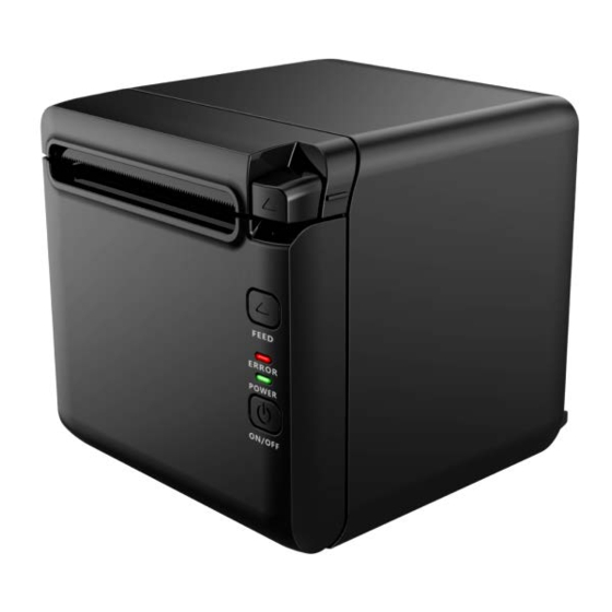
RP-700User’s Manual 3 Appearance and components 3.1 Appearance and modules Fig. 3.1-1 Schematic drawing of appearance and modules 1—To p cover 2—Cutter 3—Plate n ro ller 4—Paper e nd sensor 5—Paper guide 6—Micro switch 7—Cutter cover 8—Mi ddle cover 9—Cover ope n spa nner 10—Paper cabi net 11—Paper near e nd sensor 12—FEED button... - Page 11 RP-700User’s Manual Press the button to connect power; press the button for a long time to disconnect the power. e Top cover status detection sensor (14) Detect the printercover status (open/closed). Paper presence sensor (12) Detect the paper presence / absence status when continuous paper is used; detect the paper marks when marked paper is used.
-
Page 12: Led And Buzzer
RP-700User’s Manual 3.2 LED and buzzer 1) Functions of LED LED name Status Description Always on Printer power is on. Power LED (green) Printer power is off. Printer is in normal status. Error LED (red) Flash Printer is in error status or paper near end status. Buzzer Beep Printer is in error status. -
Page 13: Installation
If any item is damaged or missing, please contact your dealer or the manufacturer. 4.2 Printer installation 1) RP-700 supports two working methods: out put the paper from the front or the top when place the printer horizontally on the table. When the printer is placed horizontally on the table, the incline installation angle should not exceed 5°, otherwise the paper near end... -
Page 14: Power And Communication Interface
RP-700User’s Manual Fig.4.2-3Printer maintenance and operation space 4.3 Power and communication interface 4.3.1 Power connection 1) Ensure that the power switch is turned off; 2) Insert the powerplug into the corresponding socket on the back of the printer. Caution: When the printer is not in use for a long period of time, disconnect the power cord from the printer. -
Page 15: Usb Interface Connection
RP-700User’s Manual 4.3.3 USB interface connection 1) Ensure that the power switch is turned off; 2) Plug the USB cable into corresponding interface in place as shown in the figure; 3) Connect the other end of USB cable to the host. 4.3.4 Cash drawer connection 1) Ensure that the power switch is turned off;... - Page 16 RP-700User’s Manual Fig. 4.4-2 Schematic drawing of paper roll installation/replacement Caution: Adjust the paper guide according to the paper specification: install the paper guide at the position of 57.5 for 57.5 wide paper roll; install the paper guide at the position of 80 for 80 wide paper roll;...
-
Page 17: Paper Near End Position Adjustment
RP-700User’s Manual Paper near end position adjustment Fig. 4.5-1 Schematic drawing of paper near end position adjustment (output paper from the top) Fig. 4.5-2 Schematic drawing of paper near end position adjustment (output paper from the front) - 12 -... -
Page 18: Power-On And Self-Test
RP-700User’s Manual The following diameter of core shaft of paper roll supported by the printer are as following: OD of 16.2mm for plastic core shaft, OD of 20.8mm for paper type core shaft; adjust the paper near end sensor to adjust the application method and paper near end alarm function for core shaft with different outer diameters. - Page 19 RP-700User’s Manual Using Hexadecimal dumping mode: 1) Entering Hexadecimal dumping mode in the following ways: a. Open the printer mechanism and turn on the printer while pressing the feed button. Release the button after the printer alarms (LED flashes and buzzer beeps). b.
-
Page 20: Routine Maintenance
RP-700User’s Manual 5 Routine maintenance Caution: Before starting routine maintenance, ensure that the printer power is turned off. Do not use organic solvents like gasoline or acetone. When cleaning sensors, do not turn on the printer power until the pure alcohol has completely evaporated. -
Page 21: Interface Signal
RP-700User’s Manual 6 Interface signal 6.1 Serial interface The serial interface of the printer is compatible with RS-232 standard, and its interface socket is D-SUB25 socket. Signal Signal definition Function — House ground Output Data output Input Data input — Not connected Input Data device is ready... -
Page 22: Usb Interface
RP-700User’s Manual USB interface 1) Parameters Data transmission: Support USB2.0 full speed protocol. Connector (Printer end): USB B type socket. Support USB HUB. 2) Interface signal definition and function Pin No. Signal name Description VBUS Power DATA- Data minus DATA+ Data plus Ground Table 6.3-1 USB interface definition... -
Page 23: Double Communication Interface
RP-700User’s Manual 2) Interface signal definition Fig.6.4-1 Ethernet interface Interface adopts 10/100BASE-T standard which complies with IEEE802.3. The interface signal is defined as below: Pin No. Signal name Description Data transmission + Data transmission - Data receiving + Not connected Not connected Data receiving - Not connected... -
Page 24: Power Interface Definition
RP-700User’s Manual 6.6 Power interface definition 1) Power interface signal definition (100-240V AC): Fig.6.4-1 Schematic drawing of power interface Pin No. Signal name Table 6.6-1 Power interface definition 2) Main control board power interface definition (24V DC): Fig.6.6-2 Schematic drawing of 24V power interface 6.7 Cash drawer interface signal definition 1) Electrical features ... - Page 25 RP-700User’s Manual 3) Interface signal definition Signal Functions Frame Ground DRAW ER 1 Cash drawer 1 driving signal DRSW Cash drawer status detection signal Cash drawer driving power DRAW ER 2 Cash drawer 2 driving signal Circuit share ground Table 6.7-1Cash drawer interface definition Caution: ...
-
Page 26: Troubleshooting
RP-700User’s Manual 7 Troubleshooting When the printer has any problem, refer to this chapter for solution. If the problem still cannot be solved, please contact your local dealer or manufacturer for assistance. 7.1 Printer doesn’t work Problem Possible causes Solution Printer is not connected to Connect the printer to power supply. -
Page 27: Power Management
RP-700User’s Manual 8 Power management The power management of RP-700 has four operation modes: Off, Standby, Active, Sleep. Printer will enter standby mode after powering on the printer or completing printing task. Printer will enter sleep mode if there is no printing task for 5 minutes in standby mode. -
Page 28: Dump Mode
RP-700User’s Manual 9 DUMP mode There are two methods to enter DUMP mode: 1) Command method: Send 1D 28 41 02 00 00 01 2) Manual mode: Open the top cover, press and hold the FEED button, and turn on the printer power, then close the paper cabinet and release the button after the ERROR LED flashes. -
Page 29: Appendix Button Configuration
RP-700User’s Manual Appendix Button configuration PARAMETER SETT ING BY FEED BUTT ON MAI N MENU Exit -> Print Se lf Test -> Confi guration -> CONFI GURATI ON Exit W ithout Save ->1 Exit W ith Save ->2 Co mmunication ->3 Back To Last ->1... - Page 30 RP-700User’s Manual 1 Bit ->2 2 Bits ->3 Ha nds haki n -> HANDSHAKI NG: DTR/DS Back Last ->1 Menu DTR/DSR ->2 XON/XOFF ->3 Data -> DATA ERROR SETTI NG: Print ? Receive Error Back Last ->1 Menu Ignored ->2 Print '?' ->3 Rx Buff Si ze...
- Page 31 RP-700User’s Manual closed Cut pa per whe n ->4 power o n No c ut paper ->5 whe n power o n Disable ->6 Buzzer ->4 BUZZER: Ena ble d Back To -> Last Menu Ena ble -> Disable -> Print Settings ->5 PRI NT SETTI NGS...
- Page 32 RP-700User’s Manual 0 mm -> 1 mm -> 3 mm -> 5 mm -> 7 mm -> 9 mm -> CR Co mma nd ->6 CR COMMAND: Disable Back To -> Last Menu Enable -> Disable -> Code Pa ge ->7 CODE PAGE...
- Page 33 RP-700User’s Manual Back To Last ->1 Menu Paper Low ->2 PAPER LOW Alarm AL ARM: Ena ble Back To -> Last Menu Ena ble -> Disable -> Stop Print ->3 STOP PRI NT W hen PAPER W HEN PAPER LOW : Disable Back To ->...
- Page 34 To EXI T,ho ld button down least 1 second Print NV Bit ma p -> Cutter Test -> Print Statistics -> RP-700 STATISTICS TCUT TLFS ONTI ME EthernetCo nfi gurati -> EthernetCONFI GURATI O Reset ->1...
Need help?
Do you have a question about the RP-700 and is the answer not in the manual?
Questions and answers