Table of Contents
Advertisement
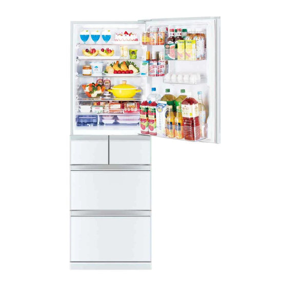
SERVICE MANUAL
Models
MR-B46Z-W-C
MR-B46Z-P-C
Model name
indication
(Inside this door)
NOTE:
• RoHS compliant products have <G> mark on the spec name plate.
CONTENTS
1. SPECIFICATIONS ••••••••••••••••••••••••••••••••••••••••••••••••••••••••••2
2. WIRING DIAGRAM ••••••••••••••••••••••••••••••••••••••••••••••••••••••••4
3. OUTLINES AND DIMENSIONS •••••••••••••••••••••••••••••••••••••••••6
4. REFRIGERANT CIRCUIT ••••••••••••••••••••••••••••••••••••••••••••••••7
5. TROUBLESHOOTING•••••••••••••••••••••••••••••••••••••••••••••••••••••8
5-1 FUNCTION OF OPERATION PANEL •••••••••••••••••••••••••••••8
5-2 FLOWCHART OF SELF-CHECK •••••••••••••••••••••••••••••••• 23
5-3 BLOCK DIAGRAM OF PRINTED CIRCUIT BOARD •••••••• 27
5-4 AUTO ICE-MAKER ••••••••••••••••••••••••••••••••••••••••••••••••• 27
5-5 FLOWCHART OF TROUBLE CRITERION •••••••••••••••••••• 31
5-6 TROUBLE CRITERION OF MAIN PARTS •••••••••••••••••••••••• 39
5-7 TEST POINT DIAGRAM OF CONTROL BOARD •••••••••••• 44
6. NAMES OF THE PARTS ••••••••••••••••••••••••••••••••••••••••••••••• 49
7. DISASSEMBLY INSTRUCTIONS ••••••••••••••••••••••••••••••••••••• 50
C ••••••Taiwan
PARTS CATALOG (OAB162)
No. OAH162
Advertisement
Table of Contents
Troubleshooting

Related Manuals for Mitsubishi Electric MR-B46Z-W-C


Summary of Contents for Mitsubishi Electric MR-B46Z-W-C
- Page 1 No. OAH162 SERVICE MANUAL Models MR-B46Z-W-C MR-B46Z-P-C Model name indication CONTENTS (Inside this door) 1. SPECIFICATIONS ••••••••••••••••••••••••••••••••••••••••••••••••••••••••••2 2. WIRING DIAGRAM ••••••••••••••••••••••••••••••••••••••••••••••••••••••••4 3. OUTLINES AND DIMENSIONS •••••••••••••••••••••••••••••••••••••••••6 4. REFRIGERANT CIRCUIT ••••••••••••••••••••••••••••••••••••••••••••••••7 5. TROUBLESHOOTING•••••••••••••••••••••••••••••••••••••••••••••••••••••8 5-1 FUNCTION OF OPERATION PANEL •••••••••••••••••••••••••••••8 5-2 FLOWCHART OF SELF-CHECK •••••••••••••••••••••••••••••••• 23 5-3 BLOCK DIAGRAM OF PRINTED CIRCUIT BOARD ••••••••...
- Page 2 SPECIFICATIONS SPECIFICATIONS MR-B46Z-C Power supply V,Hz 110V, 60 Hz Total capacity 1821 × 600 × 699 Dimensions (H × W × D) Polyester resin coated steel Cabinet Food liner ABS resin Cabinet Foamed polyurethane (Cyclopentane) Insulation Freezer door Foamed polyurethane (Cyclopentane) Refrigerator door Foamed polyurethane (Cyclopentane) Freezer...
- Page 3 ELECTRICAL PARTS SPECIFICATIONS MR-B46Z-C Model TKA91E23DAH Power supply 110V, 60 Hz Rated input 33.7 (1620 rpm) Compressor Starting current 4 (Current limiter) Running current 0.78 (1620 rpm) Winding resistance (A.T. 20 ºC) 12.4 Ω Model MM3-71CCV or KA-122-LATL00 Ambient temperature ºC Motor protector Time...
-
Page 4: Wiring Diagram
WIRING DIAGRAM MR-B46Z-C ( SKELETON WIRING DIAGRAM ) The wiring diagram in the dashed line is the same as the one attached to the products. ICE GEAR BOX I./C. S./V. TEMP. CONTROL BOARD MOTOR DAMPER MOTOR DAMPER MOTOR DAMPER (ON DISPLAY PANEL) THERMOPILE t°... - Page 5 MR-B46Z-C ( ACTUAL WIRING DIAGRAM ) CONTROL BOARD PLUG CN9S CN5D CN3A CN2A CN4A CN50G CN1A ELECT BOX 5 3 1 7 6 5 4 21 19 17 16 REACTOR GRAY WHITE SKY BLUE VIOLET BLACK 1 2 3 4 5 REFRIGERATOR COMPARTMENT 1 2 3 4 5 6...
-
Page 6: Outlines And Dimensions
OUTLINES AND DIMENSIONS Unit: mm MR-B46Z-C (Display) (Display) (Cabinet) (Pitch between the rear wheels) (Pitch between the front wheels) (Excluding the adjustable support cover) (Including the adjustable support cover) Distance between the refrigerator body and the wall to open the door to 90 degrees REQUIRED SPACE FOR INSTALLATION (Including the... -
Page 7: Refrigerant Circuit
REFRIGERANT CIRCUIT MR-B46Z-C Left-hand side condenser Right-hand side condenser Muffler Evaporator Suction pipe Capillary tube ø 1.6 x ø 0.70 x 2720 Cabinet pipe Charge pipe (High pressure Back-side condenser side) ø 4 Dryer #150 Charge pipe (Low pressure side) ø 6.35 Compressor OAH162... -
Page 8: Troubleshooting
TROUBLESHOOTING 5-1 FUNCTION OF OPERATION PANEL MR-B46Z-C (1) Function of normal operation will cause the operable icons to light up. Touching To save power, all displays other than are usually turned off (it turns off if there is no operation for about 30 seconds). Detail Setting ECO GUIDE Example: When setting the... - Page 9 (2) Demonstration mode for shop display Setting Within 1 minute after power is turned on, touch , and simultaneously for 5 seconds. When the setting is complete, 2 short beeps sound and is lit. Demonstration mode is not available when the temperature of freezer compartment is –7°C or lower. Panel operation mode during demonstration mode During the demonstration mode, is continuously lit.
- Page 10 (5) Fine adjustment of temperature (Fine adjustment of temperature is available for refrigerator compartment, the freezer compartment and the versa compartment. ) To Control the Temperature More Precisely (Temperature Fine Adjustment Mode) The temperature can be set to 19 different levels for the refrigerator compartment and freezer compartment, while it can be set to 24 different levels for the versa compartment (5 levels when set to Soft-Freezing and 19 different levels for Freezing).
- Page 11 (6) Service Diagnostics Function 1) Outline • The chart below shows the outline of service diagnostics function. • “Service diagnostics function entry” needs to be set in order to perform each check mode. • After the service diagnostics function entry, Touch to select the serial number for the check mode to be performed.
- Page 12 2) Compressor rotational speed change mode Setting With the ice making compartment door open, touch simultaneously for 3 seconds until 2 short beeps sound. blinks. With the ice making compartment door open. Touch to select blinking With the ice making compartment door open, touch for 3 seconds until 2 short beeps sound.
- Page 13 Changing the rotational speed After setting this mode, rotational speed of the compressor changes every time is touched. The ones place and tens place of the rotational speed (rps) is displayed separately. (Basically the compressor starts operation at level 10, however, it may be different depending on models, or as a result of specification change.) Normal <Change of rotational speed>...
- Page 14 3) Damper Operation Mode Setting With the ice making compartment door open, touch simultaneously for 3 seconds until 2 short beeps sound. blinks. With the ice making compartment door open, touch to select the blinking With the ice making compartment door open, touch for 3 seconds until 2 short beeps sound.
- Page 15 Opening and closing dampers (1) Touch to select the damper to be set. Each touch of changes the damper type along with a short beep. The serial number described in a) indicates the selected damper. The selected damper is displayed using the serial number (1: refrigerator ~ 13: ceiling R) in numeric order repeatedly. (2) To open the damper, light up by touching .
- Page 16 4) Thermistor temperature check mode Setting With the ice making compartment door open, touch simultaneously for 3 seconds until 2 short beeps sound. blinks. With the ice making compartment door open, touch to select the blinking With the ice making compartment door open, touch for 3 seconds until 2 short beeps sound.
- Page 17 c) Ones place of the thermistor temperature Display of corresponds to the values 8, 4, 2, and 1 respectively. The sum of the values corresponding to the lit indicators is the ones place of thermistor temperature. Corresponding Display values d) Plus and minus sign of the thermistor temperature Plus and minus signs of thermistor temperature are represented by display Thermistor temperature signs...
- Page 18 5) Error history display mode The errors occurred in the past can be observed as an error history. Use this mode when the actual problem of the refrigerator is different from the error that was displayed when the service-call received. The error history display mode offers two ways of display.
- Page 19 Display method Display method of the error code is the same as self check error display. (Refer to 5-2(3)); however, all indicators used for the display of error code light up simultaneously for 3 seconds before the first error code is displayed (“pre-display”). e.g.) When errors occurred in the following order: Refrigerator fan motor error (E31) Communication error of operation panel (E01)
- Page 20 6) Setting adjustment mode The temperature of each compartment and the energization rate of the heaters can be adjusted by touching the buttons on the operation panel. There are two modes. In the “setting adjustment mode”, the setting temperature of the compartment is adjustable.
- Page 21 ii. Select the adjustment level of the set temperature by touching Each touch of changes the adjustment level of the set temperature along with a short beep. There are 5 adjustment levels of set temperature, and the selected level is displayed. Change of the set Adjustment level Temperature adjustment display...
- Page 22 Door Alarm System : Door alarm has been installed so that one will not forget to close the door. • The alarm beeps in the following cases: 1. Any of the doors is left open. 2. The refrigerator fan motor or the box fan motor has a failure. 3.
-
Page 23: Flowchart Of Self-Check
5-2 FLOWCHART OF SELF-CHECK MR-B46Z-C (1) Troubleshooting with self-check This refrigerator has a self-check feature to clarify and indicate where and what the trouble is. You can perform operation checks and identify malfunction of electric or electronic parts. Error history is recorded and can be displayed by the refrigerator. Self-check Error history mode (Refer to 5-1.(6)5)) Problem may recover automatically. - Page 24 (2) Timing in self-check Trouble of Defrost heater : Self-check is conducted after defrosting. (Make sure to check the display before unplugging the power cord because it is automatically reset once the power cord is unplugged.) Trouble of Ice maker : Touch for 5 seconds to operate the automatic ice maker.
- Page 25 Display Error Detecting method Corrective Display Trouble Check point Control code (*3) measures Tens place Ones place Trouble of There is a short or open 1. Connector CN9S on control board, Repair the • The compressor is ON, 2-pin wire to wire connector contact failure.
- Page 26 Display Error Detecting method Corrective Display Trouble Check point Control code (*3) measures Tens place Ones place Trouble of ice The gear box operation 1. Connector CN9S on control board, ice gear Repair the 100 minutes later, the maker gear is not finished in 30 sec- box 6-pin wire to wire connector.
-
Page 27: Block Diagram Of Printed Circuit Board
5-3 BLOCK DIAGRAM OF PRINTED CIRCUIT BOARD MR-B46Z-C Operation P.C. board • Setting up temperature, quick mode and eco mode for each compartment • Display of self-check • Outside air thermistor • Alarm Control board Control circuit of refrigerator Inverter control circuit of compressor •... - Page 28 (3) Operation by ice making test Completion The sensor lever The ice tray is The water pump Touch for 5 sec- turned over and detects the amount When abnormality motor operates. onds. of ice. return. occurs, the error code (See 5-2(1) “• Self- Set the water tank in place The sensor lever once The ice tray turns over...
- Page 29 Installing the tank pipe Insert the tank pipe into the water Connect the tank pipe to the Install the tank packing tank. water supply pump. Tank Pipe Check that there are no foreign objects between the tank pipe and the water supply Tank Packing Water Tank pump.
- Page 30 (6) Troubleshooting for automatic ice maker *First, make sure that is not lit. There is a possibility of a failure on the ice making gear box, deficiency in cooling performance, an error in the detection of water supply, or detection of full ice level in the ice storage box. 1.
-
Page 31: Flowchart Of Trouble Criterion
5-5 FLOWCHART OF TROUBLE CRITERION MR-B46Z-C Excessive cooling No cooling, poor cooling Is the temperature of Is the temperature of Set the temperature to Set the temperature to refrigerator compart- refrigerator compart- “Low”. “High”. ment, set to “Low”? ment, set to “High”? Open the refrigerator Keep the food away Proceed to [6] on page... - Page 32 Excessive cooling Poor cooling Set supercool chilling to Is supercool chilling set to Release the supercool Is supercool chilling set? ”Low”. ”Low”? chilling setting. Open the refrigerator com- Only food around the air Keep the food away from partment door and attach a Proceed to [6] on page 36.
- Page 33 Poor cooling Is the set temperature of freezer compartment set to “High”? Set the temperature to “High”. Proceed to “The refrigerator fan motor does not Does cool air blow from air outlet when opening the refrigerator com- partment door and attaching a magnet bar on the door switch ? work”...
- Page 34 Inverter-related indication “Compressor does not operate” Error Abnormality Possible cause Symptom Corrective measures code Trouble of • There is any The com- Replace the control board. inverter circuit trouble in the pressor circuit which does not detects phase rotate. current of com- pressor.
- Page 35 Inverter-related indication “Compressor does not operate” Error Abnormality Possible cause Symptom Corrective measures code 1. Locate the trouble and decide on the measures. • Failed wiring • Poor connection The compres- • Decide the measures by checking the followings. continuity of connectors sor cannot be (1) Poor connector connections.
- Page 36 Poor cooling Short-circuit the terminals of the compulsory Check the following and explain the defrosting terminals (CN7M) on the control board to actuate Yes (heats up) result: half-open door, gap between the compulsory defrosting function and check whether the gaskets, the amount of ice. defrost heater is working properly.
- Page 37 Excessive cooling Poor cooling Is the temperature of Is the temperature of Set the temperature to Set the temperature to vegetable compartment vegetable compartment “Low”. “High”. set to “Low”? set to “High”? Is the temperature of Set the temperature to freezer compartment “Middle”...
- Page 38 Excessive cooling No cooling; poor cooling only applies to versa compartment. Is the compartment set to Power Save Mode? Which operation mode is the Which operation mode is versa compartment set to? Release the versa compartment set to? Power Save Mode.
-
Page 39: Trouble Criterion Of Main Parts
5-6 TROUBLE CRITERION OF MAIN PARTS MR-B46Z-C Component/ Part Mounted Check Method and Criterion Position Part Name In the machine Compressor Model TKA91E23DAH White chamber at the rear side of the Rated input 33.7 (1620 rpm) frame Starting current 0.78 (1620 rpm) Running current A (For only 1 minute after startup) Black... - Page 40 Component/ Part Mounted Check Method and Criterion Part Name Position Motor damper In the fan grille Measure the winding resistance. for chilled and for freezer ice making com- compartment Normal Abnormal (faulty) partment (The connector Winding Open ( ) or is in the back of Blue-White short circuit...
- Page 41 Component/ Part Mounted Check Method and Criterion Position Part Name At the bottom of Vegetable Measure the resistance with a tester. (Ambient temperature: Room temperature) compartment the vegetable heater compartment (inside poly- urethane foam) The connectors Normal Abnormal (faulty) are in the con- nector box on 2.0 k (Approx.) Open circuit (...
- Page 42 Part Mounted Component/ Check Method and Criterion Part Name Position Defrost Thermistor Measure the resistance with a tester according to the following graph. thermistor (Thermistor resistance values against temperature.) Evaporator • Resistance measured under the ambient temperature from -50 to +50 Ice making 1.
- Page 43 Component/ Part Mounted Check Method and Criterion Part Name Position On the ceiling of Interior LED It lights up while the refrigerator compartment door is open. (If the the refrigerator (12 V DC) LED lighting door stays open for 60 minutes in a row, the LED automatically goes duration out.
-
Page 44: Test Point Diagram Of Control Board
5-7 TEST POINT DIAGRAM OF CONTROL BOARD MR-B46Z-C OAH162... -
Page 45: Troubleshooting For Supercool Freezing Operation
5-8 TROUBLESHOOTING FOR SUPERCOOL FREEZING OPERATION Supercool freezing means “supercool freezing” and “hot freezing”. 5-8.1 FAQ Symptom/Problem Possible cause Explanation to the customer/Solution “Supercool freezing” does not keep foods Improper “ supercool freezing operation ” fresh.“Supercool freezing” does not work. •... - Page 46 5-8.2 Failure diagnosis Diagnosis made with food Prepare two pouches of ready-meal-style curry. Freeze one in the freezer and supercool-freeze the other in the versa compartment. Compare the texture of the ingredients, especially potatoes, in the curry. Put a pouch of ready-meal-style curry in the versa compartment, and touch the icon for Put the other pouch of ready-meal-style curry in the freezer.
- Page 47 5-8.3 Ice maker thermopile (ice maker sensor) The ice maker thermopile is fi xed on the ice maker with tape. 1. Diagnostic procedure <Outline> • In the “Thermistor check mode”, check the following: Response and Detected temperature. Response check: Make sure that the detected temperature changes by placing your hand under the sensor.
- Page 48 5-8.4 Failure diagnosis for the thermopile (for both versa compartment thermopile and ice maker thermopile) 3. Outline and detected temperature of the thermopile • 2 kinds of temperature information (voltage) are output from the thermopile. Vtamb: Temperature information about the thermopile itself ( ambient temperature) Vtobj: Temperature information about the object to be detected by the thermopile (infrared ray) Each output changes between 0 V ~ 5 V.
-
Page 49: Names Of The Parts
NAMES OF THE PARTS MR-B46Z-C Refrigerator Compartment About 0°C to 6°C Glass Shelf Interior Light Adjustable Pocket (Small) The glass shelves are Uses 6 LEDs. Adjustable Pocket reversible. (Large) Adjustable Pocket (Medium) (With Egg Shelf) Air Outlet If food with a high water content is placed near the air outlets, it may freeze. -
Page 50: Disassembly Instructions
DISASSEMBLY INSTRUCTIONS MR-B46Z-C Before the power plug is removed from the socket, be sure to conduct a series of ice making test operations by touching the Replace the parts after the power plug is removed. In the procedures 2, 3, 4, and 5, 3 kinds of screws and 2 kinds of rivets are used. Do not mistake one for another when installing them. - Page 51 OPERATING PROCEDURE PHOTOS Upper case cover Photo 2 (7) Lift the upper case cover. (See figure 6.) Ceiling of slide case Partition for chilled compartment (8) While pressing the end of the position indicated with the right, press the upper case cover to the left and warp it to Partition for tank remove.
- Page 52 OPERATING PROCEDURE PHOTOS Partition for chilled compartment Partition for tank Photo 4 (15) Disengage the tabs on the right and the left of the partition for chilled compartment by lifting them up. (See photo 4.) (16) Pull out the partition for chilled compartment together with the partition for tank toward you, then lift them to remove them.
- Page 53 OPERATING PROCEDURE PHOTOS Photo 6 2. Parts inside the refrigerator compartment: Connector Screw cap Control panel, Duct R Interior Cover of water supply pump motor Door switch for refrigerator compartment, ice making com- partment and versa compartment. (1) Remove the parts in the refrigerator compartment. Connector box (2) Remove the screw .
- Page 54 OPERATING PROCEDURE PHOTOS Photo 13 Cover of water supply pump motor Cover of water supply pump motor (6) Remove the screw, and lift the cover of water supply pump motor, then disconnect the connector. (See photo 13.) (7) Cut the lead wires from the cover of the water supply pump motor (See figure 10.), then pull up the lead wires to be removed from the cover of the water supply pump motor.
- Page 55 OPERATING PROCEDURE PHOTOS 3. Parts inside the ice making compartment, versa compart- Photo 15 ment, vegetable compartment, and freezer compartment : Partition I Partition S Partition I Partition S Packing (F) Partition I/S cover Partition I/ S Cover (Ice maker) Ice tray lock lever Ice tray Automatic ice maker assembly...
- Page 56 OPERATING PROCEDURE PHOTOS Cover (Ice maker) Photo 20 (8) Remove the screw and 2 connectors. (See photos 20, 21.) Connector Screw Ice tray lock lever Ice tray lock (9) Turn the ice tray lock lever 45 degrees as shown in Figure 12. lever Slide the lever to the right to remove it.
- Page 57 OPERATING PROCEDURE PHOTOS Caution on installation Figure 16 Ice maker thermopile Hook the 2 lower tabs onto the ice maker and then fit the upper tab into place. (See figure 15.) Figure 15 Upper tab Lower tabs When attaching tape, beware that the Route the lead wires as shown in Figure 13, and fix the lead tape does not cover the hole.
- Page 58 OPERATING PROCEDURE PHOTOS Evaporator Photo 25 (17) DEF thermistor Remove the 4-pin connector that is stowed in the contoured Brazed section section of inner liner. Evaporator Detach the brazed section of piping. Remove the tab protrud- ing from the inner liner to remove the evaporator. (See photo Defrost 25, figures 17, 18.) heater-1...
- Page 59 OPERATING PROCEDURE PHOTOS Defrost heater-2 Figure 19 Drip tray Heater roof (18) Detach the defrost heater-2 from the tab on the inner liner. Slide the defrost heater-2 out towards you. Remove the defrost heater from the heater roof. (See figure 19.)Remove the strips of double sided tape on the drip tray, then the drip tray.
- Page 60 OPERATING PROCEDURE PHOTOS Defrost thermistor Photo 30 (19) Cut the nylon fastener and detach the defrost thermistor from the evaporator. (See photo 30.) The defrost thermistor and the evaporator pipe heater are connected to the 4-pin connector. Cut the lead wires of the defrost thermistor at the base of the 4-pin connector.
- Page 61 OPERATING PROCEDURE PHOTOS Photo 35 4. Ceiling of vegetable compartment (1)Remove the 2 rivets and pull out the ceiling of the vegetable Ceiling of vegetable compartment toward you. (See photo 35.) compartment Vegetable compartment LED (2) Remove the 2 screws. (See photo 36.) Photo 36 Vegetable compartment Rivet...
- Page 62 OPERATING PROCEDURE PHOTOS Photo 40 6. Adjustable support cover Adjustable supports Removing (1) Pull the left and right sides of the support covers to the front to remove them. Installing (1) After adjusting the adjustable supports, install the adjustable support cover by sliding back and forward. Before installing the adjustable support cover, be sure to Adjustable support cover adjust the adjustment.
- Page 63 OPERATING PROCEDURE PHOTOS Photo 43 8. Compressor cover Drain pan Box fan Screws Compressor cover (1) Remove the 8 screws for compressor cover on the back of the refrigerator. (See photo 43.) Drain pan (2) Remove the screw. (See photo 44.) Compressor cover Caution...
- Page 64 FIGURES Compressor (1) Pierce the charge pipes (high pressure side and low pressure side) using the piercing tool, and connect the increased safety explosion-proof vacuum pump to the refrigerant circuit. Vacuum up the refrigerant and discharge it to the outside. (2) Cut the discharge and the suction pipes using a pipe cutter.
-
Page 65: Door Adjustment
Door adjustment <Adjusting refrigerator compartment doors> • Common elements First, check the installation condition. If the adjustment bolt is not in contact with the floor, lower the bolt, and adjust it so that the caster is slightly above the floor. When the refrigerator is installed in the corner of the room, the bolt of the refrigerator may sink into the floor and cause the refrig- erator to tilt. - Page 66 HEAD OFFICE: TOKYO BUILDING, 2-7-3, MARUNOUCHI, CHIYODA-KU, TOKYO 100-8310, JAPAN Copyright 2016 MITSUBISHI ELECTRIC CORPORATION Published: May 2016 No. OAH162 Made in Japan Specifications are subject to change without notice.