
Related Manuals for norbar 43228


Summary of Contents for norbar 43228
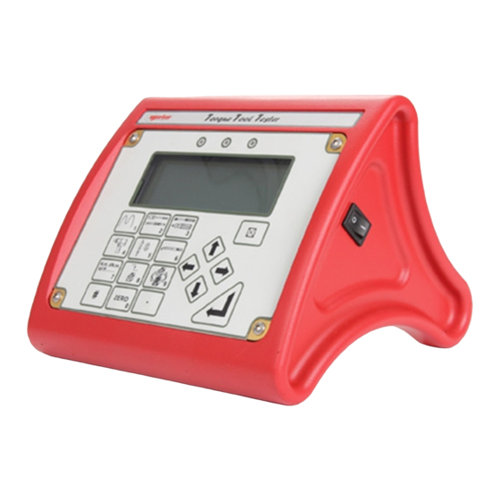
- Page 1 OPERATOR’S MANUAL TORQUE TOOL TESTER (TTT) SERIES 3 FOR USE WITH TTT’S FITTED WITH VERSION 37712.305 SOFTWARE Part Number 34308 | Issue 4 | Original Instructions (English)
-
Page 3: Table Of Contents
CONTENTS Introduction Parts included Accessories Features and Functions Set Up Preparation Set Up for use Flow Diagrams Measure User units Using the key pad Screen Layout Modes of measurement Power saving & power down Limits Transducer Interface Transducer Leads Available Specifications PIN Connections Connector Type... -
Page 4: Introduction
3 transducer connectors. • Automatically recognises any ‘SMART’ Norbar transducer. Can also work with most mV/V transducers from Norbar or other manufacturers. • 13 Torque units, plus the ability to specify USER measurement units up to a maximum of 6 characters. -
Page 5: Set Up
SET UP Preparation NOTE: If the equipment is used in a manner not specified by the manufacturer, the protection provided by the equipment may be impaired. Ancillaries Connector Transducer Selection Switch 9 V d.c. input ON (I) / OFF (O) Switch Serial Port Connector Transducer Connectors Back view... -
Page 6: Set Up For Use
NOTE: The set up is password protected, the default password is 000000. TIP: If password is lost, contact Norbar quoting the coded number in brackets on the password menu. TIP: When in a set up screen, after entering one option press the down arrow to enter the next. - Page 7 2. Settings Setting Options (defaults) Comment ENGLISH (default), FRANCAIS, DEUTSCH, ITALIANO, ESPAÑOL, LANGUAGE Set language of operation. DANSK, NEDERLANDS, SUOMI, NORSK, SVENSKA, PORTUGUES. Any 6 numeric characters PASSWORD Set Password. (default = ‘000000’). DATE & TIME Set date DD/MM/YY or MM/DD/YY. 24 hour clock with date.
-
Page 8: Flow Diagrams
Flow Diagrams All set up menus are numbered on the TTT for ease of identification. Menu Structure and Limits Flow Diagram SWITCH ON DISPLAY TRANSDUCER DISPLAY DETAILS LOGO TRANSDUCER SMART MEASURE DETAILS TRANSDUCER ? SCREEN RETURN TO MEASURE EXIT 17. SET UP SOFTWARE # XXXXX.XXX 1.LIMITS SETTINGS... - Page 9 Measure Flow Diagram...
- Page 10 Settings Flow Diagram 29. SET PASSWORD LANGUAGE LANGUAGE 31. ENTER 32. NEW PASSWORD PASSWORD IS PASSWORD PASSWORD 33. SET 35. SET PASSWORD DATE TIME TIME & DATE 37. SET 87. SELECT PASSWORD FREQUENCY MODE MODE FREQUENCY 26. SET UP/SETTINGS LANGUAGE PASSWORD DATE &...
-
Page 11: Measure
Press ‘ZERO’ to zero displayed reading. TIP: The measurement display may not zero if outside +/-3% of transducer capacity. This may be due to transducer overstrain. Return defective transducer to Norbar. Select measurement mode required. TIP: If any measurement mode does not memorise the measurement value, ensure that the ‘TRIGGER FROM’... -
Page 12: User Units
User Units This feature allows the USER to specify custom measurement units that are displayed after the measurement value and printed on the serial port. Any mV/V transducer conforming to the specifications in the TRANSDUCER INTERFACE section can be used. Typical examples could be load or pressure transducers. -
Page 13: Screen Layout
Screen Layout TARGET 1=100 N∙m 112.34 STOP PRINT N∙m IMPULSE TOOL (500 Hz) _∏_#=0 Display Instruction Press to select target value and associated limits to be used. Time/Date shown if no targets set. Measurement reading. Press to exit. Indicates when to stop loading in CLICK &... - Page 14 Function N∙m, dN∙m, lbf∙ft ……. Selection of enabled torque units. PRINT reading and RESET. To view transducer details in track mode. Shows: Serial #, Part Number, Units & Rated Capacity. Clockwise & anticlockwise mV/V Calibration figures. Angle option programmed (for use with Pro-Log instrument) Clockwise &...
-
Page 15: Modes Of Measurement
Modes of Measurement Mode Mode How it Works Visual Representation (Frequency) TRACK Follows signal. (500 Hz) Dial & Electronic (500 Hz) Holds the highest reading until RESET by the user. [The highest reading can Impulse Tool be automatically reset if (500 Hz) AUTO is selected for PEAK MEMORY RESET. -
Page 16: Power Saving & Power Down
Power Saving & Power Down Battery life can be greatly increased from a minimum of 14 hours by making use of power down. If no key is pressed or measurement reading taken in the specified time, the TTT will enter power down. The following will be displayed: SAVING POWER PRESS ANY KEY TO CONTINUE... -
Page 17: Limits
Limits Limits can be selected In Measure by pressing The target is shown at the top left of the screen and if no limits have been set, the TIME & DATE will be shown. If limits are available but not selected, ‘↓↑LIMITS OFF’ will be shown. The limit status is shown in 4 ways: On the display showing LO / OK / HI next to the torque value (updated at 3 Hz). -
Page 18: Transducer Interface
If any of the transducer’s parameters are changed i.e. re-calibration of mV/V value, the transducer’s stored parameters must be edited prior to use. (‘NON-SMART’ only). Norbar transducers with the following suffix are all suitable for use with the TTT: Suffix Description XXXXX.IND... -
Page 19: Specifications
10 way push-pull panel socket. TIP: If the display shows ‘SMART TD NOT INITALISED’ it is likely that: Unmodified ETS transducer connected. The transducer lead may have a broken connection. ‘SMART’ transducer may have lost its stored data, return to Norbar. -
Page 20: Ancillaries
Rotary transducer angle output (Channel A). Rotary transducer angle output (Channel B). TIP: The angle output is available for a Norbar Rotary Transducer. For use see Rotary Transducer manual. External Print / Reset Pins 1 & 2 are intended for use as an EXTERNAL PRINT / RESET:-... -
Page 21: Analogue Output
If the output is measured against PIN 13 (0V) the signal will always be positive, with zero torque around 2.5V. TIP: Some transducers (Norbar Annular type) will give a negative output change for a positive torque. This is because they are designed to measure reaction torque. -
Page 22: Serial Port
SERIAL PORT The serial port is for sending data to a PC or serial printer. When the TTT is measuring, data can be output on the serial interface automatically when the AUTO RESET timer operates or when the 'PRINT / RESET' key is pressed. The data can include the measured value, units of measurement and time/date. -
Page 23: Hyperterminal
Limits The serial port will output LO / OK / HI when the limits are being used. Some software, including the Norbar ‘Torque Wrench Calibration Software’ (Part 37705.XXX), will not accept LO / OK / HI characters. To remove LO / OK / HI set OUTPUT LIMITS to ‘NO‘. -
Page 24: Maintenance
Your TTT has been supplied with a certificate of calibration. To maintain the specified accuracy it is recommended that the TTT is recalibrated at least once per year. Re-calibration should be carried out at Norbar or by a Norbar approved agent, where all the facilities to ensure the instrument is functioning at maximum accuracy are available. -
Page 25: Repair
Repair Repair should be carried out at Norbar or by a Norbar approved agent, where all the facilities to ensure the instrument is functioning at maximum accuracy are available. NOTE: Only remove front panel for battery replacement; there are no other parts for user repair inside. -
Page 26: Trouble Shooting
Designed to EN 61010-1 : 2010. To environmental conditions Pollution Degree 2 & Installation Category (Over voltage Category) II. Also compliant with a Norbar transducer connected. NOTE: Due to continuous improvement all specifications are subject to change without prior notice. - Page 28 Tel + 61 (0)8 8292 9777 Tel + 86 21 6145 0368 Email enquiry@norbar.com.au Email sales@norbar.com.cn NORBAR TORQUE TOOLS INC NORBAR TORQUE TOOLS INDIA PVT. LTD 36400 Biltmore Place, Willoughby, Plot No A-168, Khairne Industrial Area, Ohio, 44094 Thane Belapur Road, Mahape, Navi Mumbai –...
Need help?
Do you have a question about the 43228 and is the answer not in the manual?
Questions and answers