Table of Contents
Advertisement
Advertisement
Table of Contents

Summary of Contents for NESpace NESPACE 48/3K
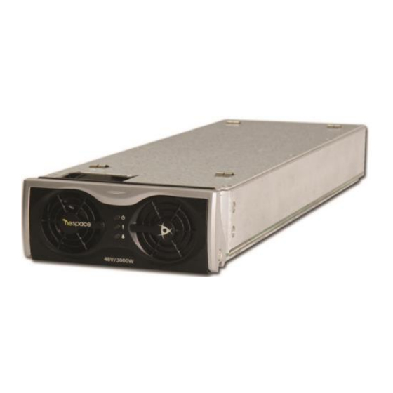
- Page 1 [Original: 2017.03] (Version 1.0) Maintenance & Operation Manual NESPACE 48/3K Rectifier Module 220V (1Phase 3Wire) AC Input -54VDC @ 55.56A DC Output 3KW Rectifier Module Reproduced with Permission Copyright © 2017 Dongah Elecomm, Ltd All rights reserved...
-
Page 2: Table Of Contents
ORMAL PERATION 3.3.1 Initial Operation Status Check ......................14 ........................... 15 ORRECTIVE EASURES 4 - NESPACE48/3K RECTIFIER MODULE CONFIGURATION ..............15 ON LED (GREEN) ............................15 2 /21 KE NESPACE KA Rectifier Control Unit Operation Manual English R 2016_07 V1_1... - Page 3 FIGURE 4-1. RECTIFIER MODULE CONNECTOR PIN ASSIGNMENT .............. 16 TABLE TABLE 2-1 OUTPUT CABLE & LUG ........................ 11 TABLE 2-2 COMMUNICATION PIN TABLE ....................113 TABLE 3-1 CORRECTIVE ACTIONS PER ALARM ..................15 3 /21 KE NESPACE KA Rectifier Control Unit Operation Manual English R 2016_07 V1_1...
- Page 4 ● Ensure that all parts and hardware are accounted for and with no deformation, damage, peeling or scratched paints, or cable damage. 《Directions in Storage》 4 /21 KE NESPACE KA Rectifier Control Unit Operation Manual English R 2016_07 V1_1...
- Page 5 (It may cause an electric shock or fire.) ● Do not try to modify this product. (It may cause an electric shock, burn, or fire.) 5 /21 KE NESPACE KA Rectifier Control Unit Operation Manual English R 2016_07 V1_1...
- Page 6 ● External transmission signal should be ≤ 60V level and ≤ 0.5A. ● Rectifier unit should be inserted and removed using the guide rail of the rectifier system, to engage connectors without damage. 6 /21 KE NESPACE KA Rectifier Control Unit Operation Manual English R 2016_07 V1_1...
- Page 7 Use special care to lockout/tagout the AC whenever necessary, check the presence of, and maintain the AC input to the power shelf, as needed. 7 /21 KE NESPACE KA Rectifier Control Unit Operation Manual English R 2016_07 V1_1...
-
Page 8: Rectifier Module Specifications
Output Ripple & Noise: ≤ 300mVp-p (max); ≤ 20mVrms (20MHz BW) Emissions 1.2.1 Electro Magnetic Interference (EMI) CE Mark, including: ✓ EN 55022:2010 +AC:2011 (Class A) ✓ /EN61204-3:2000 8 /21 KE NESPACE KA Rectifier Control Unit Operation Manual English R 2016_07 V1_1... -
Page 9: Input Surge Voltage
EN60950-1:2006/A11:2009/A1:2010/A12:2011/A2:2013 ✓ Tests conducted under CB Scheme, issued by UL International Demko A/S, CB Certificate Number DK-56640-UL (Test Report Ref. No. C16O043- A0C0 issue date 7-25-2016). 9 /21 KE NESPACE KA Rectifier Control Unit Operation Manual English R 2016_07 V1_1... -
Page 10: Nespace Shelf- Typical Installation & Cabling
Use tagout/lockout, as needed. ● Before starting any operation, carefully read the following directions. Inputs and outputs of the NESPACE rectifier is typically connected through a shelf backplane, PCB traces, filter networks, bus bars, terminals, connectors, and cables. -
Page 11: Dc Output Connection
55A: 1HOLE LUG 25SQ or greater 110A: 1HOLE LUG 50SQ or greater 110A: 1HOLE LUG 50SQ or greater -48V (M6) (M6) Figure 2-3 Output Cable Connection 11 /21 KE NESPACE KA Rectifier Control Unit Operation Manual English R 2016_07 V1_1... -
Page 12: Communication Cable Connection
3 – Shelf Initialization & Check Points with NESPACE modules When installation procedures are finished, initialize the Rectifier Shelf and perform the following functional test to check for any failures or alarms.. 12 /21 KE NESPACE KA Rectifier Control Unit Operation Manual English R 2016_07 V1_1... -
Page 13: Installation Check List
4) Verify that the rack Frame Ground has been connected to the main ground busbar. 5) Check if the I/O cable has been correctly connected. 6) Verify that all installed NESPACE Rectifier Modules have been fully inserted. 3.2 Rectifier Module Insertion & Removal 3.2.1 Rectifier Module Installation... -
Page 14: Rectifier Module Removal
Check that alarms are not shown (as activated) on the LCD display and that the LCD displays the present status correctly. Note: For additional details, see the NESPACE-KA Rectifier Control Unit Operating Manual 14 /21 KE NESPACE KA Rectifier Control Unit Operation Manual English R 2016_07 V1_1... -
Page 15: Corrective Measures
* Alarm contact.type can be set arbitrarily to NO or NC(Normally Open or Normally Closed) 4 4 - NESPACE48/3K Rectifier Module Configuration 4.1 ON LED (GREEN) The ON LED is lit (GREEN) when the Rectifier Module is in normal operation. 15 /21 KE NESPACE KA Rectifier Control Unit Operation Manual English R 2016_07 V1_1... -
Page 16: Fail Led (Red)
* When output is not functioning or voltage falls below DC UV limit (for any reason). 4.3 NESPACE48/3K Rectifier Module Connector Pinout Figure 2-1. Rectifier Module Connector Pin Assignment 5 - Rectifier Module Operation 16 /21 KE NESPACE KA Rectifier Control Unit Operation Manual English R 2016_07 V1_1... -
Page 17: Rectifier System Operation
If the OV condition is not recovered, replace the Rectifier Module and repeat this restart process to check that the replacement module clears the alarm. 17 /21 KE NESPACE KA Rectifier Control Unit Operation Manual English R 2016_07 V1_1... -
Page 18: Rectifier Maintenance
5.3 Adding Rectifier Module To expand the system capacity, rectifier modules are hot-swappable so may be inserted into vacant slots while the Rectifier Shelf is powered up normally. 18 /21 KE NESPACE KA Rectifier Control Unit Operation Manual English R 2016_07 V1_1... -
Page 19: Problem Solving & Fault Fixing
3) Slide in a new Rectifier Module along the mechanical guides until it reaches the 19 /21 KE NESPACE KA Rectifier Control Unit Operation Manual English R 2016_07 V1_1... - Page 20 V1.0 : Version 1.0 DCF : DC Fail ERR : ERRor DCOV : DC Over Voltage ENT : ENTer DCUV : DC Under Voltage LCA : Load Current Ampere 20 /21 KE NESPACE KA Rectifier Control Unit Operation Manual English R 2016_07 V1_1...
- Page 21 Information in this document is proprietary to Dongah Elecomm No information contained here may be copied, translated, transcribed or duplicated by any form without the prior written consent of Dongah Elecomm. Reproduced with Permission 21 /21 KE NESPACE KA Rectifier Control Unit Operation Manual English R 2016_07 V1_1...
Need help?
Do you have a question about the NESPACE 48/3K and is the answer not in the manual?
Questions and answers