Table of Contents
Advertisement
Quick Links
Advertisement
Chapters
Table of Contents

Summary of Contents for Areva MiCOM C264
- Page 1 MiCOM C264/C264C Bay Computer Technical Guide C264/EN T/A14...
- Page 3 Technical Guide C264/EN T/A14 MiCOM C264/C264C Page 1/2 MiCOM C264/C264C BAY COMPUTER CONTENT Safety & Handling C264/EN SA/A14 Introduction C264/EN IT/A13 Technical data C264/EN TD/A13 Functionnal Description C264/EN FT/A13 Hardware Description C264/EN HW/A13 Connection C264/EN CO/A14 Installation C264/EN IN/A13 Application...
- Page 4 C264/EN T/A14 Technical Guide Page 2/2 MiCOM C264 BLANK PAGE...
- Page 5 Safety & Handling C264/EN SA/A14 MiCOM C264/C264C SAFETY & HANDLING...
-
Page 7: Table Of Contents
Safety & Handling C264/EN SA/A14 MiCOM C264/C264C Page 1/12 CONTENT INTRODUCTION HEALTH AND SAFETY Health and Safety Installing, Commissioning and Servicing DECOMMISSIONING AND DISPOSAL TECHNICAL SPECIFICATIONS FOR SAFETY HANDLING OF ELECTRONIC EQUIPMENTS PACKING AND UNPACKING GUARANTIES COPYRIGHTS & TRADEMARKS Copyrights Trademarks WARNINGS REGARDING USE OF T&D EAI PRODUCTS... - Page 8 C264/EN SA/A14 Safety & Handling Page 2/12 MiCOM C264/C264C BLANK PAGE...
-
Page 9: Introduction
Safety & Handling C264/EN SA/A14 MiCOM C264/C264C Page 3/12 INTRODUCTION This document is a chapter of the MiCOM C264C/C264 documentation binder. It describes the safety, handling, packing and unpacking procedures applicable to MiCOM C264C/C264 modular computer series and associated equipment's and software tools. -
Page 10: Health And Safety
Safety & Handling Page 4/12 MiCOM C264/C264C HEALTH AND SAFETY For all the safety purposes please refer to the AREVA T&D Safety Guide: SFTY/4L M/D11 (or later issue) and to the following chapters. WARNING: THIS SAFETY SECTION SHOULD BE READ BEFORE COMMENCING ANY WORK ON THE EQUIPMENT. - Page 11 Safety & Handling C264/EN SA/A14 MiCOM C264/C264C Page 5/12 Insulation and dielectric strength testing Insulation testing may leave capacitors charged up to a hazardous voltage. At the end of each part of the test, the voltage should be gradually reduced to zero, to discharge capacitors, before the test leads are disconnected.
-
Page 12: Decommissioning And Disposal
C264/EN SA/A14 Safety & Handling Page 6/12 MiCOM C264/C264C DECOMMISSIONING AND DISPOSAL Decommissioning: The auxiliary supply circuit in the MiCOM computers may include capacitors across the supply or to earth. To avoid electric shock or energy hazards, after completely isolating the supplies to the MiCOM computers (both poles of any dc supply), the capacitors should be safely discharged via the external terminals prior to decommissioning. -
Page 13: Technical Specifications For Safety
Safety & Handling C264/EN SA/A14 MiCOM C264/C264C Page 7/12 TECHNICAL SPECIFICATIONS FOR SAFETY The recommended maximum rating of the external protective fuse for this equipment is 16A, Red Spot type of equipment, unless otherwise stated in the technical data section of the product documentation. -
Page 14: Handling Of Electronic Equipments
C264/EN SA/A14 Safety & Handling Page 8/12 MiCOM C264/C264C HANDLING OF ELECTRONIC EQUIPMENTS A person’s normal movements can easily generate electrostatic potentials of several thousand volts. Discharge of these voltages into semiconductor devices when handling circuits can cause serious damage, which often may not be immediately apparent but the reliability of the circuit will have been reduced. -
Page 15: Packing And Unpacking
Page 9/12 PACKING AND UNPACKING All MiCOM C264/C264C computers are packaged separately in their own cartons and shipped inside outer packaging. Use special care when opening the cartons and unpacking the device, and do not use force. In addition, make sure to remove from the inside carton the supporting documents supplied with each individual device and the type identification label. -
Page 16: Guaranties
The reader should consult AREVA T&D if errors are suspected. In no event shall AREVA T&D be liable for any damages arising out of or related to this document or the information contained in it. -
Page 17: Copyrights & Trademarks
T&D. Trademarks PACiS, PACiS SCE, PACiS ES, PACiS SMT, PACiS PS, PACiS SCE, AREVA T&D, pacis.biz and pacis.com- are trademarks of AREVA T&D. Product and company names... -
Page 18: Warnings Regarding Use Of T&D Eai Products
MiCOM C264/C264C WARNINGS REGARDING USE OF T&D EAI PRODUCTS AREVA T&D products are not designed with components and testing for a level of reliability suitable for use in or in connection with surgical implants or as critical components in any life support systems whose failure to perform can reasonably be expected to cause significant injuries to a human. - Page 19 Introduction C264/EN IT/A13 MiCOM C264/C264C INTRODUCTION...
- Page 21 Introduction C264/EN IT/A13 MiCOM C264/C264C Page 1/8 CONTENT INTRODUCTION TO MiCOM INTRODUCTION TO MiCOM GUIDES Chapters description 2.1.1 Chapter Safety (SA) 2.1.2 Chapter Introduction (IT) 2.1.3 Chapter Functional Description (FT) 2.1.4 Chapter Technical Data (TD) 2.1.5 Chapter Communications (CT) 2.1.6 Chapter HMI, Local control and user interface (HI) 2.1.7...
- Page 22 C264/EN IT/A13 Introduction Page 2/8 MiCOM C264/C264C BLANK PAGE...
-
Page 23: Introduction To Micom
INTRODUCTION TO MiCOM MiCOM is a comprehensive solution capable of meeting all electricity supply requirements. It comprises a range of components, systems and services from AREVA T&D. Central to the MiCOM concept is flexibility. MiCOM provides the ability to define an application solution and, through extensive communication capabilities, to integrate it with your power supply control system. -
Page 24: Introduction To Micom Guides
MiCOM C264/C264C INTRODUCTION TO MiCOM GUIDES The guides provide a functional and technical description of the MiCOM C264/C264C computers and a comprehensive set of instructions for the computer’s use and application. MiCOM guides is divided into two volumes, as follows: Operation Guide: includes information on the application of the computers and a technical description of its features. -
Page 25: Chapter Commissioning (Cm)
This chapter includes a description of common power system applications of the MiCOM C264/C264C computer, practical examples of how to do some basic functions, suitable settings, some typical worked examples and how to apply the settings to the computer. -
Page 26: Introduction To Micom Applications
These new generations of computers, the MiCOM C264/C264C have been specially tailored for the PACiS system. A major objective, of the MiCOM C264/C264C range is to make the range as easy as possible for the customer to accept, adapt and integrate into his system and operation. - Page 27 If a specific bay type is not included, it can be created on request and loaded into the MiCOM C264/264C. The MiCOM C264/264C can be connected to a higher control levels, local control level or lower levels by way of a built-in communications interface.
-
Page 28: Micom C264/C264C
C264/EN IT/A13 Introduction Page 8/8 MiCOM C264/C264C FIGURE 2: TYPICAL USE OF A MiCOM C264 – RTU APPLICATION The figures above only show typical cases that can be mixed to handle specific constraints. Two examples illustrate this case: • System application like figure 1 might use several C264 with several communication links to SCADA (one per level of voltage for example) in order to greatly enlarge the number of communication links to SCADA. -
Page 29: Technical Data
Technical Data C264/EN TD/A13 MiCOM C264/C264C TECHNICAL DATA... - Page 31 Technical Data C264/EN TD/A13 MiCOM C264/C264C Page 1/16 CONTENT SCOPE OF THE DOCUMENT CONFORMITY GENERAL DATA Design Installation Position Degree of Protection Weight Dimensions and Connections Terminals Creepage Distances and Clearances RATINGS Auxiliary Voltage Digital inputs Digital outputs 4.3.1 DOU200 4.3.2...
-
Page 32: Micom C264/C264C
C264/EN TD/A13 Technical Data Page 2/16 MiCOM C264/C264C ACCURACY Reference Conditions Measurement Accuracy TYPE TESTS Dielectric Withstand Mechanical Test Atmospheric Test “DC” Auxiliary Supply Test “AC” Auxiliary Supply Test... -
Page 33: Scope Of The Document
C264/EN TD/A13 MiCOM C264/C264C Page 3/16 SCOPE OF THE DOCUMENT This document is a chapter of MiCOM C264 documentation binders, describing the Technical data of this computer. CONFORMITY (Per Article 10 of EC Directive 72/73/EC.) The product designated “MiCOM C264/C264C computer” has been designed and manufactured in conformance with the European standards EN 60255-6 and EN 61010-1 and with the ‘EMC Directive’... -
Page 34: Creepage Distances And Clearances
C264/EN TD/A13 Technical Data Page 4/16 MiCOM C264/C264C Conventional communication links: M3 threaded terminal ends, self-centring with wire protection for conductor cross sections from 0.2 to 2.5 mm² for BIU241 board. DIN 41652 connector; type D-Sub, 9-pin on the CPU260 board in the rear panel. -
Page 35: Ratings
Technical Data C264/EN TD/A13 MiCOM C264/C264C Page 5/16 RATINGS Auxiliary Voltage Tanks to the BIU241 board, the MiCOM C264C/C264 computers are available in four auxiliary voltage versions, specified in the table below: Version Nominal ranges Operative DC range Operative AC range 24 V 19.2 –... -
Page 36: Digital Outputs
C264/EN TD/A13 Technical Data Page 6/16 MiCOM C264/C264C Digital outputs 4.3.1 DOU200 The characteristics of the Output Relay Contacts of the DOU200 board are specified in the table below: Features Values ±24 to ±250 V External operating Voltage (U 230 V –... -
Page 37: Biu241
Technical Data C264/EN TD/A13 MiCOM C264/C264C Page 7/16 Features Values Break (in V 250 V – 8 A - cos. phi > 0.6 Maximum 15 A and 300 V Loaded contact 10,000 operations minimum Unloaded contact 100,000 operations minimum Operating time <... -
Page 38: Voltages
C264/EN TD/A13 Technical Data Page 8/16 MiCOM C264/C264C The four measurement Current Transformers (4 CT) inputs have the following characteristics: Operating range Features Nominal AC current (I Minimum measurable current 0.01 A 0.05 A Maximum measurable current 20 A Frequency 50 or 60 Hz ±... -
Page 39: Burdens
Technical Data C264/EN TD/A13 MiCOM C264/C264C Page 9/16 BURDENS Auxiliary Voltage The MiCOM C264C/C264 computer burdens are specified in the table below: Version Case size Nominal Maximum C264C (4U – 40TE) 12VA 17VA 24 V C264C (4U – 40TE) 16VA... -
Page 40: Ccu200
C264/EN TD/A13 Technical Data Page 10/16 MiCOM C264/C264C 5.3.2 CCU200 The CCU200 board burdens are specified in the table below: Nominal Maximum consumption Nominal wetting voltage (+/- Version consumption (W) 20%) per board per board 24 V 48 to 60 V... - Page 41 Technical Data C264/EN TD/A13 MiCOM C264/C264C Page 11/16 ACCURACY For all specified accuracy, the repeatability is ± 2.5% unless otherwise specified. If no range is specified for the validity of the accuracy, then the specified accuracy shall be valid over the full setting range.
- Page 42 C264/EN TD/A13 Technical Data Page 12/16 MiCOM C264/C264C TYPE TESTS Dielectric Withstand Type Test Name Type Test Standard Conditions Insulation Resistance IEC 60255-5 100 MΩ at 500 Vdc (CM & DM) Dielectric Withstand IEC60255-5 50 Hz, 1mn, 2kV (CM), 1kV (DM) IEEE C37.90...
- Page 43 Technical Data C264/EN TD/A13 MiCOM C264/C264C Page 13/16 Atmospheric Test Type Test Name Type Test Standard Conditions Damp Heat Test – Operating IEC 60068-2-3 Test Ca: +40°C / 10 days / 93% RH Cold Test - Operating IEC 60068-2-1 Test Ab: - 25°c / 96 H...
- Page 44 C264/EN TD/A13 Technical Data Page 14/16 MiCOM C264/C264C “AC” Auxiliary Supply Test Type Test Name Type Test Standard Conditions Vn ± 20% Supply variations IEC 60255-6 AC Voltage dips & short EN 61000-4-11 2ms to 20ms & 50ms to 1s...
- Page 45 Technical Data C264/EN TD/A13 MiCOM C264/C264C Page 15/16 Type Test Name Type Test Standard Conditions CM 500 V / DM 250 V via 0.1 µF Power Frequency IEC 61000-4-16 Conducted emission EN 55022 Gr. I, class A : from 0.15 to 30 MHz...
- Page 46 C264/EN TD/A13 Technical Data Page 16/16 MiCOM C264/C264C BLANK PAGE...
-
Page 47: Functional Description
Functional Description C264/EN FT/A13 MiCOM C264/C264C FUNCTIONAL DESCRIPTION... - Page 49 MiCOM C264/C264C Page 1/40 CONTENT SCOPE OF THE DOCUMENT Software features DIRECT PROCESS INTERFACE Input Check Output check Time tagging MiCOM C264/C264C MANAGEMENT Mode management 3.1.1 Operating Mode management 3.1.2 Redundancy Mode management Database management Self tests Time management 3.4.1 External clock 3.4.2...
- Page 50 C264/EN FT/A13 Functional Description Page 2/40 MiCOM C264/C264C DATA PROCESSING Binary Input Processing 6.1.1 Binary Input Acquisition 6.1.2 Binary Input Definition 6.1.3 Processing of Single Point Status 6.1.4 Processing of Double Point Status 6.1.5 Group processing Processing of Multi Point Status Measurement Input Processing 6.3.1...
- Page 51 Functional Description C264/EN FT/A13 MiCOM C264/C264C Page 3/40 USER INTERFACE Front Panel LED’s Management Local Control Display Local/Remote push-button Front serial Link RECORDS 10.1 Permanent records storage 10.1.1 Data storage 10.1.2 Fast Waveform Recording 10.1.3 Disturbance Recording 10.2 Non-permanent data storage 10.2.1...
- Page 52 C264/EN FT/A13 Functional Description Page 4/40 MiCOM C264/C264C BLANK PAGE...
-
Page 53: Scope Of The Document
Page 5/40 SCOPE OF THE DOCUMENT This document is a chapter of MiCOM C264/C264C documentation binders. It is the functional description of this computer. The hardware description is defined in HW (Hardware) chapter and all connection diagrams in chapter CO. The product capabilities, performances, environmental limits are grouped in TD (Technical Data) chapter. - Page 54 C264/EN FT/A13 Functional Description Page 6/40 MiCOM C264/C264C RTU, SCADA PACiS System, UCA2 IED T-BUS S-BUS Telecontrol UCA2 Interface 61850 Synchronsation Time tagging Computer Kernel Printing Alarms Archives Human CT, Disturb Interface (LCD) Embedded Automation (basic+AR, Synchrocheck+AVR) Configurable Automation (Fast PSL / Sequential PLC)
-
Page 55: Direct Process Interface
MiCOM C264/C264C Page 7/40 DIRECT PROCESS INTERFACE Several kind of boards can be used in MiCOM C264 and C264C. Digital Input & Outputs, Measurement acquisitions are checked to validate information/action and time tagged on any change of state or value. -
Page 56: Micom C264/C264C Management
C264/EN FT/A13 Functional Description Page 8/40 MiCOM C264/C264C MiCOM C264/C264C MANAGEMENT The computer manages its own mode, configuration (Data Bases), and time. Mode management 3.1.1 Operating Mode management The available operating modes on the computer are: Operational: the equipment is working correctly (all the functions are executed) -
Page 57: Time Management
C264/C264C using IRIG-B standard. A specific input is dedicated for this application. 3.4.2 Clock message from a SCADA gateway SCADA clock synchronisation is SCADA protocol dependent. The synchronisation message is directly acquired by the MiCOM C264/C264C through the SCADA link. -
Page 58: System Master Clock
MiCOM C264/C264C 3.4.3 System master clock For the use of MiCOM C264/C264C in a Digital Control System, the clock synchronisation can be received through the Ethernet protocol. The system master clock can be implemented in any Ethernet connected equipment mainly in: •... -
Page 59: Communications
Functional Description C264/EN FT/A13 MiCOM C264/C264C Page 11/40 COMMUNICATIONS MiCOM C264/ C264C ensure up to three different type of communications: • Telecontrol Bus (T-Bus), • Station Bus (S-Bus), • Legacy Bus (L-Bus). Main characteristics are given below. Furthermore details on the S BUS protocol implementation for MiCOM C264 is given. -
Page 60: Station Bus
Number of communication links: Two can be used with two different protocols and data destination or with the same mapping and protocol with redundancy factors. Station bus MiCOM C264/C264C behaves mainly as a server but it can be also a client of other C264 (distributed automation) or UCA2 IED. This bus is optional. -
Page 61: Sbus Protocol
Page 13/40 SBUS PROTOCOL As a server on Station BUS MiCOM C264 makes its database version available. If there are other PACIS system devices connected, it checks their database version before subscribing to them. It can be also client of protection on SBUS or another computer. -
Page 62: Direct Process Access
These DMs are used to process measurements and tap position indications. Digital outputs (DO) Two types of Digital Outputs can be integrated into the MiCOM C264: • The command DOs from the 8 DIs+4 DOs boards. -
Page 63: Data Processing
A preliminary treatment (filtering) is applied to specific Single Points (SP) in order to confirm the state. The choice of these SPs and the filtering time are fixed by the MiCOM C264/C264C configuration. If the opposite transition occurs before this delay, both transitions are discarded. -
Page 64: Processing Of Double Point Status
C264/EN FT/A13 Functional Description Page 16/40 MiCOM C264/C264C The SP resulting states are: States (Report) Goose Logic * RESET False True TOGGLING Invalid SELFCHECK FAULTY Invalid UNKNOWN Invalid SUPPRESSED Invalid FORCED RESET False FORCED SET True SUBSTITUTED RESET False SUBSTITUTED SET... -
Page 65: Group Processing
TOGGLING Invalid SELFCHECK FAULTY Invalid UNKNOWN Invalid SUPPRESSED Invalid FORCED STATE1 to FORCED False STATE N SUBSTITUTED STATE1 True to SUBSTITUTED STATE N N is fixed by MiCOM C264/C264C configuration from 2 to 32. There is no GOOSE transmission mechanism. -
Page 66: Measurement Input Processing
C264/EN FT/A13 Functional Description Page 18/40 MiCOM C264/C264C Measurement Input Processing Measurement Values can be Analogue Measurement, or Digital Measurement. Analogue Measurements are acquired from communication or from computer boards (AIU200 for DC or TMU200 for AC). Digital Measurement comes from Digital input. -
Page 67: Ct/Vt Additional Processing
Functional Description C264/EN FT/A13 MiCOM C264/C264C Page 19/40 6.3.2 CT/VT additional processing From the direct primary measurements (currents and voltages), MiCOM C264/C264C calculates and transmits: • RMS Values, current and voltage • Active, Reactive and Apparent Power • Power factor •... -
Page 68: Control Sequences
• SBO many: Selection, several Execution, until Unselection Control sequences checks On receiving a command, the control sequences execute configured checks: Operational conditions − MiCOM C264/C264C mode management (Operational, Test, Maintenance..), − IED connected − Substation control mode (Remote/Local), −... -
Page 69: Operational Modes
The objective of interlocking is to prohibit a control sequence that may violate the device operating condition (e.g. break capability, isolation…) or plant operating condition. Linked to interlocking, uniqueness of control is defined into the MiCOM C264 for itself and/or using data from other computers on SBUS. The mechanism is based on the GOOSE Control Bypass As stated earlier, various checks are required before control commands are issued. -
Page 70: Hv Control Sequences
C264/EN FT/A13 Functional Description Page 22/40 MiCOM C264/C264C HV Control Sequences 7.6.1 Control of circuit breaker Several types of circuit breaker can be managed: • Three phases or single phase circuit breaker • Synchronised or non-synchronised, with internal or external synchrocheck. -
Page 71: Automation
Programmable Scheme Logic • Programmable Logic Controller. The choice between these three solutions is time and complexity dependent. Build-in Automation functions Within the MiCOM C264/C264C 4 build-in automation functions are available and can be set directly by the user: • Auto-recloser •... - Page 72 C264/EN FT/A13 Functional Description Page 24/40 MiCOM C264/C264C Check close synchroniser controls Close Generator Network Busbar (a) Application to generator Check close synchroniser controls Close Network Network Line A CB 1 Busbar B (b) Application to two networks C0006ENa FIGURE 4 : CHECK SYNCHRONISER APPLICATIONS ~...
-
Page 73: Auto-Recloser (Ar)
Functional Description C264/EN FT/A13 MiCOM C264/C264C Page 25/40 8.1.2 Auto-Recloser (AR) 80-90% of faults on the electrical network are transient, such as lightning or insulator flashover. When a fault occurs, the Circuit Breaker is tripped in order to protect the system. -
Page 74: Trip Circuit Supervision
C264/EN FT/A13 Functional Description Page 26/40 MiCOM C264/C264C Instant of fault Operates Resets Protection Operating time Trip coil Contacts Contacts Closing circuit Contacts Contacts Transient energised separate extinguished fully open energised make fully closed fault Circuit breaker Opening Arcing Closing... -
Page 75: Automatic Voltage Regulation (Avr)
Functional Description C264/EN FT/A13 MiCOM C264/C264C Page 27/40 (a) Supervision while circuit breaker is closed (scheme H4) (b) Supervision while circuit breaker is open or closed (scheme H5) Alarm (c) Supervision with circuit breaker open or closed with remote alarm (scheme H7) - Page 76 Homing in order to adjust a transformer to the voltage of the busbar to which it will be connected • Minimisation of circulating current For each transformer, MiCOM C264/C264C acquires: • Current, voltage, active and reactive powers of the transformer secondary •...
-
Page 77: Fast Automation (Psl)
MiCOM C264/C264C Page 29/40 Fast automation (PSL) MiCOM C264/C264C provides the user the capability to build his own Programmable Scheme Logic (PSL) for Fast Automation modules. This is achieved through the use of programmable logic gates and delay timers. The input to the PSL is any combination of the status of the digital inputs, the outputs of the MiCOM C264/C264C and issued from the various communications buses (T-BUS, L-BUS, S-BUS). - Page 78 The programmable components are: • the logic gates: − "AND" logic gates, "AND logic" with relay scheme "AND logic" with MiCOM C264 C0012ENa FIGURE 10: PSL AND LOGIC GATE − "OR" logic gates, "OR logic" with relay scheme "OR logic" with MiCOM C264...
-
Page 79: Settable Inputs Of The Psl
The opto-inputs: the mapping of these inputs is user settable. Each input may be connected to more than one MiCOM C264 element or PSL input. • The MiCOM C264/C264C elements settings, which are defined using the PACiS SCE. 8.2.2 Timers 8.2.2.1... - Page 80 C264/EN FT/A13 Functional Description Page 32/40 MiCOM C264/C264C 100ms Relay scheme Drop-off MiCOM C264 Drop-off delayed input time output time Principle of drop-off delayed C0017ENa FIGURE 15: PSL DROP-OFF TIMER 8.2.2.3 Dwell timer When the input signal goes high the dwell timer immediately drives the output high for the dwell setting time.
-
Page 81: Programmable Gates
Invert Output: If this radio button is active the gate output is inverted. Configurable automation (PLC) The MiCOM C264/C264C allows the user to configure specific control sequences or automations (e.g. switching sequences, busbar transfer, load shedding, and GIS-pressure supervision) during the substation configuration phase. - Page 82 C264/EN FT/A13 Functional Description Page 34/40 MiCOM C264/C264C The Soft Logic package supports all five standard programming languages of the IEC 1131- • Sequential Function Chart, SFC (GRAFCET) • Function Block Diagram, FBD • Ladder Diagram, LD • Structured Text, ST •...
-
Page 83: User Interface
Functional Description C264/EN FT/A13 MiCOM C264/C264C Page 35/40 USER INTERFACE The user can receive information from the MiCOM C264/C264 front panel 4 different ways: LEDs − 5 reserved for MiCOM C264/C264C status − 12 Configurable for any purpose Local Control Panel (optional) −... -
Page 84: Led's Management
Select information • Enter value or string (including password) • Send Control (Bay Mode, switch gear, transformer …) Local/Remote push-button The Local/Remote push button manages the MiCOM C264/C264C operation modes: • Local • Remote Front serial Link The Front panel RS232 serial link is located under the lower flap. -
Page 85: Records
10.1.2 Fast Waveform Recording MiCOM C264/C264C Waveform recording is available with the CT/VTs board only. The inputs for the waveform records are up to 4 CT samples and 4 VT samples, and the values of the selected digital inputs and outputs. Up to 128 digital channels may be captured. -
Page 86: Disturbance Recording
C264/EN FT/A13 Functional Description Page 38/40 MiCOM C264/C264C 10.1.3 Disturbance Recording Disturbance recording can be performed: • Directly by the MiCOM computers : see FST and SST features below. Records are stored using COMTRADE 97 binary format • By the IEDs which communicate with the MiCOM computers. In this case, the computer uploads the disturbance record from the IED. - Page 87 Functional Description C264/EN FT/A13 MiCOM C264/C264C Page 39/40 The trigger can come from : • Changes of state of binary inputs (SP, DP, MP, SI or Groups) • Changes of state of digital outputs • Measurement threshold violations • Request from an operator 10.1.3.2 Slow Scan Triggered (SST)
-
Page 88: Non-Permanent Data Storage
10.2.1 Events All data change or events declared in MiCOM C264/C264C configuration database « To be logged » are stored in a circular list of 200 events. The event records are available for viewing either via the front panel LCD or remotely, via the communications ports. - Page 89 Hardware C264/EN HW/A13 MiCOM C264/C264C HARDWARE...
- Page 91 Hardware C264/EN HW/A13 MiCOM C264/C264C Page 1/22 CONTENT SCOPE OF THE DOCUMENT HARDWARE DESCRIPTION Concept 2.1.1 Components 2.1.2 Hardware Overview MiCOM C264C 2.2.1 Hardware presentation 2.2.2 Modularity 2.2.3 I/O Capabilities MiCOM C264 2.3.1 Hardware presentation 2.3.2 Modularity 2.3.3 Permissible configurations 2.3.4...
- Page 92 C264/EN HW/A13 Hardware Page 2/22 MiCOM C264/C264C BLANK PAGE...
-
Page 93: Scope Of The Document
Hardware C264/EN HW/A13 MiCOM C264/C264C Page 3/22 SCOPE OF THE DOCUMENT This document is a chapter of MiCOM C264/C264C documentation binders. It describes product hardware not in the commissioning chapter. HARDWARE DESCRIPTION Concept 2.1.1 Components The MiCOM C264C/C264 is based on a modular and scalable architecture to support dedicated hardware modules adapted to the plant data interfaces. -
Page 94: Hardware Overview
C264/EN HW/A13 Hardware Page 4/22 MiCOM C264/C264C 2.1.2 Hardware Overview MIO - Mother Board SWITCH - Board (SWU200) SWR201 - redundant 1x100BaseFx and 4x10/100BaseTx MIO - Board 10/100BaseTx Ethernet Links 100BaseFx DI - Boards (DIU200) CT/VT - Board (TMU200) 16 Digital Inputs (16 DI) -
Page 95: Micom C264C
Hardware C264/EN HW/A13 MiCOM C264/C264C Page 5/22 MiCOM C264C 2.2.1 Hardware presentation The MiCOM C264C mechanical rack has the following features: • Height: 4 U • Width: 40 TE Dimensions of this rack are in the figure bellow: 17.7 C0022ENa... -
Page 96: Modularity
C264/EN HW/A13 Hardware Page 6/22 MiCOM C264/C264C Case properties: • Case degree of protection: IP52 in standard • Front Face degree of protection: IP52 • Metallic case • Available for flush or wall mounting Ethernet 10 /100 Base T connector... -
Page 97: I/O Capabilities
Hardware C264/EN HW/A13 MiCOM C264/C264C Page 7/22 MiCOM C264C without CT/VT MiCOM C264C with CT/VT C0025ENa FIGURE 4: MiCOM C264C - MODULES ORGANISATION 2.2.3 I/O Capabilities Case Without CCU200 (DI + DO mix board) MiCOM Cx64C – I/O Capabilities Case... -
Page 98: Micom C264
C264/EN HW/A13 Hardware Page 8/22 MiCOM C264/C264C MiCOM C264 2.3.1 Hardware presentation The MiCOM C264 mechanical rack has the following features: • Height: 4 U • Width: 80 TE Dimensions of this rack are in the figure below: 413.2 10.8 408,4 12.5... -
Page 99: Modularity
FIGURE 6: MiCOM C264C – REAR PANEL OVERVIEW 2.3.2 Modularity The MiCOM C264 is available in two case version allowing flexibility and scalability in the use of the I/O modules: There is one bus versions 17 slots width for connecting boards: •... -
Page 100: Permissible Configurations
C264/EN HW/A13 Hardware Page 10/22 MiCOM C264/C264C 2.3.3 Permissible configurations MiCOM Cx64 – Admissible modules Case CT/VT AIU200 DOU200 DIU20x CCU20x Without CT/VT Up to 6 Up to 8 Up to 10 Up to 15 With CT/VT Up to 6... -
Page 101: Modules Description
A watchdog relay is incorporated into the BIU241 board giving the indication that the product is healthy. Software and hardware drive this relay on the CPU260 board. C0031ENa FIGURE 8: MiCOM C264 - BIU241 BOARD The BIU241 board provides two insulated serial links in base. - Page 102 C264/EN HW/A13 Hardware Page 12/22 MiCOM C264/C264C This following figure shows where to find the jumpers used to configure the serial links. C0032ENa FIGURE 9: BIU HARDWARE SCHEME By zooming the upper right corner of the BIU board, jumpers can be found, the possible...
- Page 103 Page 13/22 C0033ENa FIGURE 10: ZOOM ON BIU JUMPERS 2.5.1.1 Configurable communication Port 1 - RS232/422/485 Can be used for communication with SCADA, Sub-MiCOM C264 or with IEDs. The communication link characteristics are: • Asynchronous full duplex serial protocol •...
-
Page 104: Central Processing Unit And Base Communications Board - Cpu260
C264/EN HW/A13 Hardware Page 14/22 MiCOM C264/C264C 2.5.2 Central Processing Unit and base communications board – CPU260 • The CPU260 board is based on a PowerPC processor includes the 10/100BaseT Ethernet communication in base. This board is interfaced with all other boards through the main computer’s bus. - Page 105 Hardware C264/EN HW/A13 MiCOM C264/C264C Page 15/22 C0034ENa FIGURE 11: MiCOM C264 - CPU260 BOARD...
-
Page 106: Digital Inputs Unit - Diu200
1 common contact for 2 inputs • Protection against reversal polarity • The digital inputs can be configured in single or double remote signalling, pulse or digital measurement input on the same module. C0035ENa FIGURE 12: MiCOM C264 - DIU200 BOARD... -
Page 107: Digital Outputs Unit - Dou200
The +5V bus voltage is monitored to avoid issuing inadvertent commands. The digital outputs can be configured in single or double remote control or set point outputs on the same module. C0036ENa FIGURE 13: MiCOM C264 - DOU200 BOARD... -
Page 108: Circuit Breaker Control Unit - Ccu200
A self-monitoring function for the output control procedure is provided (address check, state monitoring) The +5V bus voltage is monitored to avoid issuing inadvertent commands. The digital outputs can be configured in double remote signalling only. C0037ENa FIGURE 14: MiCOM C264 - CCU200 BOARD... -
Page 109: Analogue Input Unit - Aiu200
Hardware C264/EN HW/A13 MiCOM C264/C264C Page 19/22 2.5.6 Analogue Input Unit – AIU200 The Analogue input module (AIU200) capabilities are the following: • 4 independent analogue inputs. Each AI can be configured in voltage or current range individually between: −... -
Page 110: Transducerless Measurements Unit - Tmu200
C264/EN HW/A13 Hardware Page 20/22 MiCOM C264/C264C C0038ENa FIGURE 15: MiCOM C264 - AIU200 BOARD 2.5.7 Transducerless Measurements Unit – TMU200 The transducersless measurement capabilities are the following: • 4 measurement Current Transformers (4 CT) inputs − Transformers have two ranges 1 and 5 amperes •... -
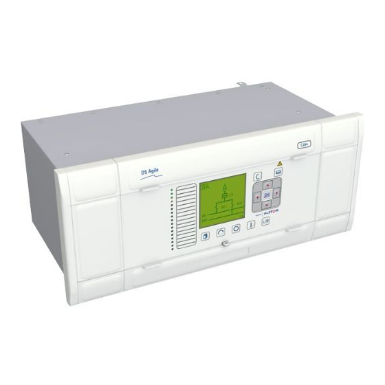
Page 111: Front Panel - Ghu240
MiCOM C264/C264C Page 21/22 2.5.8 Front panel - GHU240 Local HMI Front panel equipped MiCOM C264 computer as shown below: C0039ENb FIGURE 16: MiCOM C264 GENERAL VIEW WITH FRONT PANEL C0040ENb FIGURE 17: MiCOM C264C GENERAL VIEW WITH FRONT PANEL... - Page 112 C264/EN HW/A13 Hardware Page 22/22 MiCOM C264/C264C BLANK PAGE...
- Page 113 Connections C264/EN CO/A14 MiCOM C264/C264C CONNECTIONS...
- Page 115 Connections C264/EN CO/A14 MiCOM C264/C264C Page 1/32 CONTENT SCOPE OF THE DOCUMENT CONNECTOR BLOCKS I/O Connector Block CT/VT Connector Block Serial communications connections Optical communications connections Ethernet-based communications connections CONNECTION OF THE PROTECTIVE (EARTH CONDUCTOR) Earthing Cable fitting CONNECTION DIAGRAMS FOR EACH I/O BOARDS Power auxiliary supply and legacy ports board –...
- Page 116 C264/EN CO/A14 Connections Page 2/32 MiCOM C264/C264C BLANK PAGE...
-
Page 117: Scope Of The Document
Connections C264/EN CO/A14 MiCOM C264/C264C Page 3/32 SCOPE OF THE DOCUMENT This document is a chapter of MiCOM C264/C264C documentation binders. It describes the connectors of the product IOs connectors and the connection diagrams of each I/O boards. -
Page 118: Connector Blocks
C264/EN CO/A14 Connections Page 4/32 MiCOM C264/C264C CONNECTOR BLOCKS I/O Connector Block All the I/O connection uses a standard type of connector block with a 24-way and 5.08 mm pitch. An example of this reference of the female connector from Entrelec is: •... -
Page 119: Ct/Vt Connector Block
Page 5/32 CT/VT Connector Block MiCOM C264 uses a standard MiDOS 28 connector block for transformer connection. CT connection requires 2 dual terminal groups to allow for dual rated transformer (1A/5A). Each group has shorting contact to allow disconnection of CTs. -
Page 120: Serial Communications Connections
C264/EN CO/A14 Connections Page 6/32 MiCOM C264/C264C Serial communications connections For a serial communications interface a termination is necessary on the bus for each last device, i.e. termination resistors must be connected. These are variants with RS485 or RS422 interfaces. -
Page 121: Optical Communications Connections
Connections C264/EN CO/A14 MiCOM C264/C264C Page 7/32 (Slave) (Slave) (Slave) MiCOM C264 MiCOM C264 Relay or IED Relay or IED Relay or IED (Slave) (Slave) (Slave) (Slave) Relay or IED Relay or IED Relay or IED Relay or IED C0045ENa FIGURE 5: STAR NETWORK OR NETWORK WITH TEES –... -
Page 122: Ethernet-Based Communications Connections
Page 8/32 MiCOM C264/C264C Ethernet-based communications connections The Ethernet-based communication available in the MiCOM C264 works in full duplex mode, using either fibre optic media (ST connector) or 4 pair twisted cable. FTP: Foil Twisted Pair Only the cable insulated category 5 ( ) or insulated (STP - Shielded Twisted Pairs) with RJ45 connectors must be used. -
Page 123: Connection Of The Protective (Earth Conductor)
The earth wire must be as short as possible. All cautions have to be taken to ensure the best electrical conductivity, particularly the contact quality, stainless conductor. The impedance between the MiCOM C264/C264C Earthing terminal and the Earth must be less than 10 mΩ under 12 Volt, 100 Hz. - Page 124 C264/EN CO/A14 Connections Page 10/32 MiCOM C264/C264C First example: MiCOM C264/C264C fitted without metallic cubicle. Mechanical Earth MiCOM C264 - Rear panel Mechanical Earth C0048ENc FIGURE 8: FIRST EXAMPLE OF EARTHING PLAN...
- Page 125 Connections C264/EN CO/A14 MiCOM C264/C264C Page 11/32 Second example: MiCOM C264/C264C fitted in a metallic cubicle with other devices. Metallic cubicle Other device Earthing braid as short as possible Earth Earth Earth Earth Mount cables with Mount cables with fixings attached to...
-
Page 126: Connection Diagrams For Each I/O Boards
C264/EN CO/A14 Connections Page 12/32 MiCOM C264/C264C CONNECTION DIAGRAMS FOR EACH I/O BOARDS Power auxiliary supply and legacy ports board – BIU241 This board includes the auxiliary power supply converter, the watchdog relay, the alarm relay (NO contact), 2 optically insulated Digital Inputs (1 common for 2 DI) and 2 legacy ports (Ports N°1 / N°2). - Page 127 Connections C264/EN CO/A14 MiCOM C264/C264C Page 13/32 Connector description: Pin N°. Signal Alarm relay 2 (NO contact) Alarm relay – common 1-2 Alarm relay 1 (NO contact) Watch-dog relay (NO contact) Watch-dog relay (NC contact) Watch-dog relay – common Digital Input 1+...
- Page 128 C264/EN CO/A14 Connections Page 14/32 MiCOM C264/C264C Block diagram: BIU24x Power auxiliary supply and legacy ports board Output relays Watchdog RS232/ Serial RXD / TB RS485 link 2 TXD / TA RS232/ RS422 RXD / TB Serial RS485 TXD / TA...
-
Page 129: Central Processing Unit - Cpu260
Connections C264/EN CO/A14 MiCOM C264/C264C Page 15/32 RS232: − If the C264/BIU241/Port 1 is used -> Pin No 13 (GND) is to be earthed − If the C264/BIU241/Port 2 is used - > Pin No 15 (GND) is to be earthed RS485 / RS422: daisy chain and equipements in the same cubicle: −... - Page 130 C264/EN CO/A14 Connections Page 16/32 MiCOM C264/C264C Connector description & Block diagram: Central P rocessing Unit, CPU260 Ethernet-based communication board CONNECTORS 10/100 Base-TX Ethernet-based link RJ-45 (female) C0051ENa FIGURE 11: CPU260 BASE BOARD – CONNECTOR DESCRIPTION / BLOCK DIAGRAM...
- Page 131 Connections C264/EN CO/A14 MiCOM C264/C264C Page 17/32 Central Processing U nit, CPU260 Ethernet-Based communications board CONNECTORS 10/100 Base-TX Ethernet-based link RJ -45 (female) OPTIONAL LINK: 100 Base-FX Ethernet-based link (female) C0052ENa FIGURE 12: CPU260 BOARD WITH ETHERNET-BASED COMMUNICATIONS – CONNECTOR...
- Page 132 C264/EN CO/A14 Connections Page 18/32 MiCOM C264/C264C Central Processing U nit, CPU260 with optional IRIG-B link board CONNECTORS 10/100 Base-TX Ethernet-based link RJ -45 (female) OPTIONAL LINK: IRIG-B link C0053ENa FIGURE 13: CPU260 BOARD WITH IRIG-B INPUT – CONNECTOR DESCRIPTION / BLOCK DIAGRAM...
- Page 133 Connections C264/EN CO/A14 MiCOM C264/C264C Page 19/32 Central Processing U nit, CPU260 with optional legacy communications board CONNECTORS 10/100 Base-TX Ethernet-based link RJ -45 (female) OPTIONAL LINKS: RS232 RXD / T- TXD / T+ Serial link 3 RS232 RXD / T-...
- Page 134 C264/EN CO/A14 Connections Page 20/32 MiCOM C264/C264C Central P rocessing U nit, CPU260 base and optional communications board CONNECTORS 10/100 Base-TX Ethernet-based link RJ-45 (female) OPTIONAL LINKS: 100 Base-FX Ethernet-based link (female) RS232 RXD / T- TXD / T+ Serial...
-
Page 135: Digital Inputs Module - Diu200
Connections C264/EN CO/A14 MiCOM C264/C264C Page 21/32 Digital Inputs module – DIU200 The Digital Input module provides 16 optically isolated digital inputs (with 1 common for 2DI). Connector description: Pin N°. Signal Digital Input 1+ Digital Input 2+ Common Digital Input 1 / 2... - Page 136 C264/EN CO/A14 Connections Page 22/32 MiCOM C264/C264C Block diagram: D igital Input U nit DIU200 board Signal inputs DI10 DI11 DI12 DI13 DI14 DI15 DI16 C0056ENa FIGURE 16: DIU200 BOARD – BLOCK DIAGRAM NOTE: Different voltage ratings of DIU200 boards exist in the MiCOM C264/C264C catalogue.
-
Page 137: Digital Outputs Module - Dou200
Connections C264/EN CO/A14 MiCOM C264/C264C Page 23/32 Digital Outputs module – DOU200 The Digital Outputs Unit (DOU200) board provides 10 outputs (10 DO) using integrated relays. The DOU200 board is equipped with a 24-way 5.08 mm pitch connector. Connector description: Pin N°. - Page 138 C264/EN CO/A14 Connections Page 24/32 MiCOM C264/C264C Block diagram: D igital Output U nit DOU200 board Signal outputs DO 1 DO 2 DO 3 DO 4 DO 5 DO 6 DO 7 DO 8 DO 9 DO 10 C0057ENa FIGURE 17: DOU200 BOARD – BLOCK DIAGRAM...
-
Page 139: Circuit Breaker Control Unit - Ccu200
Connections C264/EN CO/A14 MiCOM C264/C264C Page 25/32 Circuit breaker Control Unit - CCU200 The Circuit breaker Control Unit (CCU200) board provides 8 digital inputs (8 DI with one common for 2DI) and 4 double pole outputs (4 DO) using integrated relays. - Page 140 C264/EN CO/A14 Connections Page 26/32 MiCOM C264/C264C Block diagram: Circuit breaker CCU 200 Control U nit board Digital Inputs Digital Outputs CO 1 CO 2 CO 3 CO 4 C0058ENa FIGURE 18: CCU200 BOARD – BLOCK DIAGRAM NOTE: Different voltage ratings of CCU200 boards exist in the MiCOM C264/C264C catalogue.
-
Page 141: Analogue Input Module - Aiu200
Connections C264/EN CO/A14 MiCOM C264/C264C Page 27/32 Analogue Input module – AIU200 The Analogue input module (AIU200) provides 4 independent Analogue inputs (4AI). The AIU200 board is equipped with a 24-way 5.08 mm pitch connector. Connector description: Pin N°. Signal... - Page 142 C264/EN CO/A14 Connections Page 28/32 MiCOM C264/C264C Block diagram: Analogue Input U nit AIU200 board Signal inputs mA/V AI 1 mA/V AI 2 mA/V AI 3 mA/V AI 4 RS232 Serial link for calibration te st only C0059ENa FIGURE 19: AIU200 BOARD – BLOCK DIAGRAM...
-
Page 143: Transducerless Measurements Unit Module -Tmu200
Connections C264/EN CO/A14 MiCOM C264/C264C Page 29/32 Transducerless Measurements Unit module –TMU200 The Transducerless Measurements Unit module (TMU200) provides 4 transducerless voltage inputs (VT) and 4 transducerless current inputs (CT). The TMU200 board is equipped with a standard MiDOS 28 connector (see Figure 2: Standard MiDOS 28 connectors). - Page 144 Transducerless Transducerless voltage inputs voltage inputs C0060ENa FIGURE 20: CT/VT BOARD – BLOCK DIAGRAM NOTE: When connecting the system transformers, check to make sure that the secondary nominal currents of the system and the MiCOM C264 device agree.
-
Page 145: Front Panel
Connections C264/EN CO/A14 MiCOM C264/C264C Page 31/32 Front panel The front panel includes the TTL interface (for the communication to the CPU260 module) and one non-insulated RS232 interface. This serial port is dedicated to a PC for maintenance and settings. - Page 146 C264/EN CO/A14 Connections Page 32/32 MiCOM C264/C264C MiCOM C264C Front panel: RS232 port: This serial port is dedicated to a PC for Maintenance and Settings. C0062ENb FIGURE 22: MiCOM C264C FRONT PANEL...
- Page 147 Installation C264/EN IN/A13 MiCOM C264/264C INSTALLATION...
- Page 149 Front Panel Reinstall WIRING INSTALLATION General wiring Power supply wiring I/O board wiring Networks wiring POWER UP DELIVERED MiCOM C264 SETTING COMPUTER Checking default settings: p command Settings to enter Input new settings: c command Checking communication setting Installing new software version...
- Page 150 C264/EN IN/A13 Installation Page 2/18 MiCOM C264/264C COMPUTER PERIPHERAL INSTALLATION 11.1 External master clock connection 11.2 Printer installation...
-
Page 151: Scope Of The Document
C264/EN RS record sheet. REQUIREMENT MiCOM C264 boot setting and software installation is carried out using a Windows PC with common utilities and serial/Ethernet link to the computer. The PACiS CD-ROM System installation is needed to run the C264’s install software on the Host PC. -
Page 152: Personal Computer
It should be care of selecting into PC application the PORT 1 or 2 that is physically wired to the computer. Communication wiring The serial link between PC PORT and MiCOM C264 Maintenance port is made via RS232C straight line. DB 9... -
Page 153: Delivery Reception
Installation C264/EN IN/A13 MiCOM C264/264C Page 5/18 DELIVERY RECEPTION Delivery reception is composed of: • Packing inspection and opening • Delivery form checking • Feeling up commissioning Packing inspection and opening On receipt of the unit inspect the packaging for any signs of damage, if there is inform the delivery agent. -
Page 154: Mechanical Mounting
Page 6/18 MiCOM C264/264C MECHANICAL MOUNTING The chapter C264/EN HW gives the dimension of MiCOM C264 rack, the fixation diameters and their position. If electric screw driver is used the torque limitation should be set to the small diameters of the screws. -
Page 155: Wiring Installation
Page 7/18 WIRING INSTALLATION Wiring has to be prepared before installation. The MiCOM C264 is delivered with all required connectors. The wire diameters stated in chapter C264/EN CO are mandatory. Tighten the screws in a cross pattern (e.g. top left, then bottom right etc), take care not to over torque the screws. -
Page 156: Power Up Delivered Micom C264
The computer has a default factory IP address and alias, these need to be changed to the application specific values. Connect the RS cable between the MiCOM C264 and the PC, and run the hyper-terminal program. If the parameters and wiring are correct, the connection is established, press enter and a prompt is displayed on terminal: >... -
Page 157: Settings To Enter
Installation C264/EN IN/A13 MiCOM C264/264C Page 9/18 Settings to enter The settings to enter are: - • factory host PC name: your maintenance laptop network name • factory host IP address: your maintenance laptop IP@ • factory target name: should be the Computer name defined by SCE for its database •... -
Page 158: Checking Communication Setting
(to check the Ethernet parameters) > p CR If connection cannot be established, check the parameters on MiCOM C264 via the serial link. Verify that the PC parameters, host name, IP address, and domain are correct. Refer to the MF Maintenance faultfinding document for further help. -
Page 159: Downloading Database
Checking connection Before downloading the database it is recommended to check the Ethernet link between the PC_SMT and the MiCOM C264. This is done using a windows DOS session by typing: - Ping xxx.xxx.xxx.xxx (where xxx is the IP address of the target computer). -
Page 160: After Computer Installation
C264/EN IN/A13 Installation Page 12/18 MiCOM C264/264C AFTER COMPUTER INSTALLATION Installation is now complete. The commissioning procedure can now continue, remember to update the RS record sheet. In the event of any problems refer to the chapter C264/EN MF Maintenance and faultfinding. - Page 161 Installation C264/EN IN/A13 MiCOM C264/264C Page 13/18 Check the number of the right version of the computer’s you need to install and click on the next button: FIGURE 3: LICENSE AGREEMENT Choose the “I accept the agreement” radio button then click on the next button: FIGURE 4: DESTINATION DIRECTORY Check that you have enough disk space.
- Page 162 C264/EN IN/A13 Installation Page 14/18 MiCOM C264/264C Then click on the next button: FIGURE 5: SELECT COMPONENT Choose the components you want to install, you may have already an FTP tool or other components you don’t want to erase. Then click on the next button: FIGURE 6: START MENU Choose if you want an item in your start menu.
- Page 163 Installation C264/EN IN/A13 MiCOM C264/264C Page 15/18 FIGURE 7: ADDITIONAL TOOL Choose if you want a PACiS FTP desktop icon. Otherwise you ca the choice to launch this tool from the start menu. FIGURE 8; READY TO INSTALL Click on the next button at this time a progress dialog box will appear. Wait for the...
- Page 164 C264/EN IN/A13 Installation Page 16/18 MiCOM C264/264C FIGURE 9: INSTALL COMPLETED Now you have the choice to launch the PACiS FTP Server. The connection with the computer needs to be established to make this operation success. To see the files that have installed otherwise to check the installation is completed see the...
- Page 165 Installation C264/EN IN/A13 MiCOM C264/264C Page 17/18 COMPUTER PERIPHERAL INSTALLATION Additional options to be installed. Check the delivery form for any options that should be installed, software options are integrated into the software version but are activated from PACiS SCE.
- Page 166 C264/EN IN/A13 Installation Page 18/18 MiCOM C264/264C BLANK PAGE...
- Page 167 Application C264/EN AP/A13 MiCOM C264/C264C APPLICATION...
- Page 169 Application C264/EN AP/A13 MiCOM C264/C264C Page 1/52 CONTENT SCOPE OF THE DOCUMENT REQUIREMENTS COMPUTER DEFINITIONS Kind of computers Computer definitions Adding a computer Default components Adding objects to the computer component Computer’s component relations 3.6.1 Standard relation definitions 3.6.2 Right relations 3.6.3...
- Page 170 C264/EN AP/A13 Application Page 2/52 MiCOM C264/C264C 5.4.4 Alarms 5.4.5 Mean value Profile of Counter 5.5.1 General 5.5.2 State labels SITE Bay Specific Models Build-in functions Data Point SUBSTATION CONTROL SYSTEM Computer System Information UCA2 Mapping Legacy Bus (L-BUS) 7.3.1 Configure a physical port 7.3.2...
-
Page 171: Scope Of The Document
MiCOM C264/C264C Page 3/52 SCOPE OF THE DOCUMENT The present document is a MiCOM C264/C264C chapter of the documentation binder. This document is intended to present you how to configure the Computer. It is the chapter Application (AP) of this Product. -
Page 172: Computer Definitions
C264/EN AP/A13 Application Page 4/52 MiCOM C264/C264C COMPUTER DEFINITIONS Kind of computers There are two models of computers: C264 and C264C. The C264 is a large size computer (80TE) and C264C is the compact one (40TE). The height for the both computers is 4U. -
Page 173: Default Components
Application C264/EN AP/A13 MiCOM C264/C264C Page 5/52 Default components When you add from the “Objects Entry” view, for example a C264C computer you will obtain the following sub-tree of the computer definition with the default components as follow: Bin der Hardware... -
Page 174: Adding Objects To The Computer Component
C264/EN AP/A13 Application Page 6/52 MiCOM C264/C264C Adding objects to the computer component To get this view you need to select the C264 object in the Substation Control System (Scs) sub-tree of the Object view, the Objects entry view contains the objects you need to add into your computer definition depending on the application you want. -
Page 175: Computer's Component Relations
Application C264/EN AP/A13 MiCOM C264/C264C Page 7/52 Computer’s component relations 3.6.1 Standard relation definitions This relation allows you to locate the computer in a specific “Substation” at the “Site” level. is located in: <null> 3.6.2 Right relations These relations are inherited from the upper level. -
Page 176: Computer Boards General
C264/EN AP/A13 Application Page 8/52 MiCOM C264/C264C Computer boards general After adding a DIU200 board you will get the following sub-tree for this board definition: Computer’s relation: has for profile: <null> need a MPS board profile with for example the following Labels:... -
Page 177: Computer Specific Board
Application C264/EN AP/A13 MiCOM C264/C264C Page 9/52 Computer specific board Computer’s boards have the following features: : 16 DI : 10 DO : 4 AI (AI range +short/long acquisition cycle) : 8 DI, 4 DO (take good care the DO 4,5,6,7 are defined but not used) -
Page 178: Computer Attributes
C264/EN AP/A13 Application Page 10/52 MiCOM C264/C264C COMPUTER ATTRIBUTES 4.1.1 General This view contains the general attributes of the computer, Ethernet address, Network name for the computer. FIGURE 4 : GENERAL ATTRIBUTES Name used for logging, alarms, … Indicate if the computer has a CPU 260 with IRIG B option synchronised by the S- BUS. - Page 179 Application C264/EN AP/A13 MiCOM C264/C264C Page 11/52 DI Voltage ~40% Filtering time Deboucing time C0113ENa FIGURE 6 : EVENTS Event time tag: t0 Transition time: t2 Toggling delays are defined as the following: Invalid State TOGGLING xPS State Changes New Valid State...
-
Page 180: Counter Attributes
C264/EN AP/A13 Application Page 12/52 MiCOM C264/C264C 4.1.4 Counter attributes FIGURE 9: COUNTER ATTRIBUTES Debouncing delay: debouncing time in ms, range [0..10] by step of 1 ms Number of software faults allowed in period else Computer remains in HALT mode... -
Page 181: Computer Profiles
Application C264/EN AP/A13 MiCOM C264/C264C Page 13/52 COMPUTER PROFILES Profile definition For several Data Points profile defines the same treatment. It means that if you define the DPS of all Switch Gears with the same profile to be logged they all will be logged. -
Page 182: Profile Location
C264/EN AP/A13 Application Page 14/52 MiCOM C264/C264C Profile location As all system treatments profiles are defined in the Scs hierarchy. The Relations involved are “has for profile” from all DP (in Site or Scs hierarchy) to a special profile. Profiles of SPS, DPS, MPS 5.3.1... -
Page 183: State Labels
Application C264/EN AP/A13 MiCOM C264/C264C Page 15/52 5.3.2 State labels The state labels of a DPS is as the following, with to parts one is specific to the kind of DP (single, double or multiple) and one is for invalid states: FIGURE 11 : STATE LABELS for SPS: Set/Reset, for MPS: I among N (<16) state0 to state15/undefined... -
Page 184: State Treatment
C264/EN AP/A13 Application Page 16/52 MiCOM C264/C264C 5.3.3 State treatment FIGURE 12 : STATE TREATMENT Treatments can be: • No archive, No logging • Archive and Logging • Archive only Archived means send to OI server and the LCD display. -
Page 185: Alarms
Application C264/EN AP/A13 MiCOM C264/C264C Page 17/52 5.3.5 Alarms FIGURE 14 : ALARMS Alarm generation: Appearance only mean 1 alarm, Appearance and disappearance means 2 alarms Defined means the state is alarmed Spurious: the DP is Set and never Reset... -
Page 186: State Labels
C264/EN AP/A13 Application Page 18/52 MiCOM C264/C264C 5.4.2 State labels FIGURE 16 : MV PROFILE STATE LABEL IED is disconnected Board acquisition is saturated Digital measurement coding error 4 to 20 mA DC input when under 4 mA 4 to 20 mA DC input when under 4 mA 5.4.3... -
Page 187: Alarms
Application C264/EN AP/A13 MiCOM C264/C264C Page 19/52 5.4.4 Alarms Alarm management is as the xPS management you can define the same features for each valid or invalid sates. FIGURE 18 : MV PROFILE ALARMS 5.4.5 Mean value PACiS OI archive computation mean per hour/day/week/month/years. -
Page 188: Profile Of Counter
C264/EN AP/A13 Application Page 20/52 MiCOM C264/C264C Profile of Counter 5.5.1 General FIGURE 20 : COUNTER PROFILE GENERAL Counter (Accl on UCA2) is an integer then the coefficient to get energy on the OI. Activate pulse conversion or not on the OI. -
Page 189: Site
Application C264/EN AP/A13 MiCOM C264/C264C Page 21/52 SITE Configure voltage level Bay level − Define a bay BusBar, BusSectioner, BusCoupler, Feeder, Transformer, Generator and Motor… Voltage level L/R substation Bay Specific L/R bay SBMC Order running Models Switch gear Circuit Breaker... -
Page 190: Substation Control System
C264/EN AP/A13 Application Page 22/52 MiCOM C264/C264C SUBSTATION CONTROL SYSTEM Computer System Information By default you will get this system informations: FIGURE 22 : SYSTEM INFORMATION DB compatibility (SPS) DB incoherency SPS DB switch control (SPC) Device link (SPS) Device mode (DPS) -
Page 191: Uca2 Mapping
Application C264/EN AP/A13 MiCOM C264/C264C Page 23/52 UCA2 Mapping Is mandatory system information. FIGURE 23 : UC2 MAPPING Legacy Bus (L-BUS) Defining a legacy network depending on the use to be done with the computer you need to configure a communication port. - Page 192 C264/EN AP/A13 Application Page 24/52 MiCOM C264/C264C 7.3.1 Configure a physical port This port can be configured on the CPU or the BIU board. FIGURE 24 : PHYSICAL PORT System UCA2 device: Computer Hardware binder inside of which there are all boards port 1&2 on BIU board RS232 or RS485...
- Page 193 Application C264/EN AP/A13 MiCOM C264/C264C Page 25/52 Port transmission parameter FIGURE 26 : PORT TRANSMISSION PARAMETER This port is configured as is: RS485 T103 Modbus Common transmission parameters speed: 1200 to 64000 parity: NO/Even/Odd stop: 1/1.5/2 (bit duration) byte: 7/8...
-
Page 194: Lbus Communication
C264/EN AP/A13 Application Page 26/52 MiCOM C264/C264C 7.3.2 LBUS Communication 7.3.2.1 Definition FIGURE 27 : LBUS COMMUNICATION DEFINITION Legacy network binder One LBUS definition for each physical port (or channel) Relation “has for main comm. port” for each legacy protocol filled with : “RS232/485 port 2”... -
Page 195: Ied On Legacy Bus
Application C264/EN AP/A13 MiCOM C264/C264C Page 27/52 7.3.2.2 Communication port attributes FIGURE 28 : LBUS ATTRIBUTES Retry after failure [1..10] TO for IED answer [1..300] Time synchronisation Delay before disconnecting IED [10..100] Kind of synchronisation: T&D EAI or None 7.3.3 IED on legacy bus •... -
Page 196: Ied On T103
C264/EN AP/A13 Application Page 28/52 MiCOM C264/C264C IED definition FIGURE 29 : IED DEFINITION Process data profiles AI, print IED data on UCA2, Bricks IED LBUS Acquisition +DREC definition IED system information IED Diag: connection, synchronisation, DREC LBUS mapping Linked features, graphic for IO 7.3.4... - Page 197 Application C264/EN AP/A13 MiCOM C264/C264C Page 29/52 7.3.4.2 Hierarchy FIGURE 31 : IED HIERARCHY System information upon IED LBUS − Communication − Disturbance − Synchronisation System Information on UCA2 − IEDDIAG − RDRE (disturbance) Legacy BUS Mapping − to be linked to Site_DP −...
- Page 198 C264/EN AP/A13 Application Page 30/52 MiCOM C264/C264C 7.3.4.3 T103 - Recall Lenght 1 Lenght 2 C Control Flow control (Class / Function send ack confim) A Adress 1/2 @ GTW from SCADA Link User Data or ASDU Identifier Protocolar :...
- Page 199 Application C264/EN AP/A13 MiCOM C264/C264C Page 31/52 7.3.4.5 T103 - DPS mapping Two single information to create Double DPS. FIGURE 34 : DPS MAPPING Mapping name Relation to “Site” DPS has 2 relation (if public ASDU): “has for IED address”...
- Page 200 C264/EN AP/A13 Application Page 32/52 MiCOM C264/C264C 7.3.4.6 T103 - MV mapping Same goal MV rank + MV protocol format FIGURE 35 : MV MAPPING Mapping name to Site MV, relation “has for IED address” T103 ASDU T103 Function Number...
- Page 201 Application C264/EN AP/A13 MiCOM C264/C264C Page 33/52 7.3.4.7 T103 - SPC mapping FIGURE 36 : SPC MAPPING Mapping name to Site , relation “has for IED address” T103 ASDU T103 Function Number T103 Information Number T103 ASDU MV 3, 9rank (several MV) T103 Common Address of ASDU.
- Page 202 C264/EN AP/A13 Application Page 34/52 MiCOM C264/C264C 7.3.4.8 T103 - DCP mapping Open/Close SPC in DCP FIGURE 37 : T103 DCP MAPPING Mapping name to Site , relation “has for IED address” T103 ASDU T103 Function Number T103 Information Number T103 Common Address of ASDU.
- Page 203 Application C264/EN AP/A13 MiCOM C264/C264C Page 35/52 7.3.4.9 T103 - IED Acquisition FIGURE 38 : IED ACQUISITION IED Type: Standard,Px3x, Px4x IED Main function type T103 (DREC) General Interrogation Sampling T103 special acquisition parameters, MV are Normalised (% Nominal) MV coefficient 1.2 2.4...
- Page 204 C264/EN AP/A13 Application Page 36/52 MiCOM C264/C264C 7.3.4.10 Disturbance Channels definition (10) (11) FIGURE 39 : DISTURBANCE CHANNEL DEFINTION Digital channel (on/off) contact, function Name given in Disturbance File T103 corresponding @ Analogue channel (Measurement) Name to give in Disturbance File...
-
Page 205: Ied On Modbus
Application C264/EN AP/A13 MiCOM C264/C264C Page 37/52 7.3.5 IED on Modbus 7.3.5.1 Attributes FIGURE 40 : IED MODBUS ATTRIBUTES System object Naming IED @ on LBUS DREC (Disturbance Recording) with basic file name uploaded 7.3.5.2 IED on ModBus Recall Query... - Page 206 C264/EN AP/A13 Application Page 38/52 MiCOM C264/C264C 7.3.5.3 Modbus - SPS Mapping FIGURE 42 : MODBUS SPS MAPPING Mapping Name => Relation to Site SPS for any treatment “has For IED Address” Word/Bit @ (depend of reading function) Bit number (with read function 3,4,7)
- Page 207 Application C264/EN AP/A13 MiCOM C264/C264C Page 39/52 7.3.5.5 Modbus - MV Mapping FIGURE 44 : MODBUS MV MAPPING Mapping Name => Relation to Site MV Word @ Not used Modbus reading function Word Not used Not used Modbus MV format (see later) 7.3.5.6...
- Page 208 C264/EN AP/A13 Application Page 40/52 MiCOM C264/C264C 7.3.5.7 Modbus – DPC Mapping FIGURE 46 : MODBUS – DPC MAPPING Mapping Name => Relation to Site DPC Word @ Bit @ (10) Modbus Writing function 6, 7 W 1, n bit...
- Page 209 Application C264/EN AP/A13 MiCOM C264/C264C Page 41/52 7.3.5.8 Modbus - IED Acquisition FIGURE 47 : MODBUS IED ACQUISITION Name given to acquisition object Standard Modbus MODICON M300 Pseudo Modbus T&D EAI S20 Standard Modbus MODICON Acquisition polling to SPS connected...
-
Page 210: Telecontrol Bus (T-Bus)
C264/EN AP/A13 Application Page 42/52 MiCOM C264/C264C Telecontrol Bus (T-BUS) Defining a SCADA network depending on the use to be done with the computer you need to configure a communication port with the SCADA. Available protocols: • IEC 60870-5-101 (T101 serial link) •... -
Page 211: Configure A Physical Port
Application C264/EN AP/A13 MiCOM C264/C264C Page 43/52 FIGURE 49 : SCADA COMMUNICATION OBJECT This object “C26X SCADA networks will manage SCADA communication. 7.4.2 Configure a physical port For DNP3 and T101 protocols a connection with a serial port is needed. -
Page 212: Tbus Communication
C264/EN AP/A13 Application Page 44/52 MiCOM C264/C264C 7.4.3 TBUS Communication 7.4.3.1 Definition The “C26X SCADA prot” object as the following definition: FIGURE 51 : C26X SCADA PROTOCOL DEFINITION System data profile definition UCA2 mapping Communication port relation... - Page 213 Application C264/EN AP/A13 MiCOM C264/C264C Page 45/52 7.4.3.2 Communication port attributes Depending on the communication protocols chosen for SCADA communication. You have different attributes to configure. T101 SCADA Communication attributes: FIGURE 52: T01 PROTOCOL ATTRIBUTES interlocking protocol: Interlocking protocol Management of the taking control...
- Page 214 C264/EN AP/A13 Application Page 46/52 MiCOM C264/C264C cause of transmission length: length of the field cause of transmission (COT). This information is important to decode the frame Address on 8 bits 1 byte Address in 16 bits 2 bytes MV periodic cycle (in s): in range [0..65534], duration cycle in seconds for sending measurements.
- Page 215 Application C264/EN AP/A13 MiCOM C264/C264C Page 47/52 SPS/DPS class: class of priority associated to the TS most middle less MV class: class of priority associated to the AI most middle less counter class: class of priority associated to the Meters...
-
Page 216: System Data Information
C264/EN AP/A13 Application Page 48/52 MiCOM C264/C264C TCP/IP address: ASDU common address: information object length: Address on 8 bits 16bits 3 bytes Address on 16 bits 8 bits 3 bytes Address on 8 bits 8 bits 8bits 3 bytes Address on 24 bits (3 bytes) 3 bytes MV periodic cycle (in s): in range [0..65534], duration cycle in seconds for sending... -
Page 217: Scada Communication Addresses
Application C264/EN AP/A13 MiCOM C264/C264C Page 49/52 7.4.4.2 Attributes To configure System information you will to deal with the following attributes: FIGURE 56 : SYSTEM INFORMATION SPS ATTRIBUTES 7.4.5 SCADA communication addresses 7.4.5.1 Definition SCADA communication addresses has the following definition:... -
Page 218: Scada Link Addresses
C264/EN AP/A13 Application Page 50/52 MiCOM C264/C264C 7.4.5.2 Attributes SCADA communication addresses has the following attributes: FIGURE 58 : SCADA COMMUNICATION ADDRESS ATTIBUTES 7.4.6 SCADA link addresses To get information on an electrical data point trough the SCADA communication link you need to configure a relation for this electrical data point. - Page 219 Application C264/EN AP/A13 MiCOM C264/C264C Page 51/52 Right-click on the “Add” button to add a relation “has for SCADA address” under the “Comp. swit. pos.” object. Then double-click on the relation to make appear the Relation link editor: FIGURE 60 : FILLING HAS FOR SCADA ADDRESS RELATION Once you’ve selected the “Gtw DPS addr”...
-
Page 220: Use Cases
C264/EN AP/A13 Application Page 52/52 MiCOM C264/C264C USE CASES Here are explanations of different types of utilisation for computers. Standalone computer For this kind of Computer UCA2 mapping can be skipped. Bay computer Computer aim is to manage specific bay like Feeder Transformer Generic and Busbar. - Page 221 Settings C264/EN ST/A13 MiCOM C264/C264C SETTINGS...
- Page 223 Settings C264/EN ST/A13 MiCOM C264/C264C Page 1/14 CONTENT SCOPE OF THE DOCUMENT Tree Panel Navigation Tree Panel Organisation CONFIGURATION OF VIEW PANELS Bay display Synchrocheck Communication display Devices display Counters Measurements Transformer Tap Position PARAMETERS/HMI PANELS Bay Panel Main LCD settings...
- Page 224 C264/EN ST/A13 Settings Page 2/14 MiCOM C264/C264C BLANK PAGE...
-
Page 225: Scope Of The Document
Page 3/14 SCOPE OF THE DOCUMENT This document is a chapter of MiCOM C264 documentation binders. It describes the Settings -or on-line- parameters, which can be modified in runtime on MiCOM Cx64 computers. The setting is done through the LCD Local Control Display which is defined in C264/EN HI (Human Interface) part. -
Page 226: Tree Panel Organisation
C264/EN ST/A13 Settings Page 4/14 MiCOM C264/C264C Tree Panel Organisation At this hierarchy level, only the left part setting is considered in this chapter. BAY_01 C264 C264 C264 Configuration Report Command C264 C264 Configuration Configuration / View / Parameters C264... -
Page 227: Configuration Of View Panels
Settings C264/EN ST/A13 MiCOM C264/C264C Page 5/14 CONFIGURATION OF VIEW PANELS Bay display • BAY01=>08 Label Select action Comment Visible master Configured Not configured Loc/rem command type Software loc/rem cmd Wired loc/rem cmd Synchrocheck • SCK01=>08 Label Select action Comment... -
Page 228: Devices Display
C264/EN ST/A13 Settings Page 6/14 MiCOM C264/C264C Devices display • DEV01=>72 Label Select action Comment Device name Not assigned …* Q72* Device type Not assigned Circuit breaker Switch disconnector Information type Not assigned Signal Command Signal with command Visible master... -
Page 229: Measurements
Settings C264/EN ST/A13 MiCOM C264/C264C Page 7/14 Measurements • RM001=>256 Label Select action Comment Not assigned Bay1* Bay2* Bay3* Bay4* Bay5* Bay6* Bay7* Bay8* Visible master Configured Not configured Transformer Tap Position • TAP01=>08 Label Select action Comment Tap changer name... -
Page 230: Parameters/Hmi Panels
C264/EN ST/A13 Settings Page 8/14 MiCOM C264/C264C PARAMETERS/HMI PANELS The differents setting panels define. Bay Panel • BAY01=>08 Label Select action Comment Bar display type No bar display Vertical bar Horizontal bar Fct.asg. num. displ. <list of measurments and counters>... -
Page 231: Display Options Bay Panel
Settings C264/EN ST/A13 MiCOM C264/C264C Page 9/14 Label Select action Comment Hold-time meas. pan. Min value = 1 Without function Scale 0-1.2 Scale 0-2 Assignment read key <1 specific configured datapoint of the menu tree> Display options bay panel •... - Page 232 C264/EN ST/A13 Settings Page 10/14 MiCOM C264/C264C Label Select action Comment Displ. synchk state Displ. autrec state...
-
Page 233: Parameters/Treatment Panels
Settings C264/EN ST/A13 MiCOM C264/C264C Page 11/14 PARAMETERS/TREATMENT PANELS Synchrocheck • SCK01=>08 Label Select action Comment Scheme Not assigned V AND Vref V AND NOT Vref NOT V AND Vref NOT V AND NOT Vref NOT V OR NOT Vref Delta <numeric value>... -
Page 234: Serial Communication
C264/EN ST/A13 Settings Page 12/14 MiCOM C264/C264C Serial Communication • COM01=>10 Label Select action Comment Baudrate Not assigned 50 Baud 100 Baud 200 Baud 300 Baud 600 Baud 1200 Baud 2400 Baud 4800 Baud 9600 Baud 19200 Baud 38400 Baud... -
Page 235: Measurements Acquisition
Settings C264/EN ST/A13 MiCOM C264/C264C Page 13/14 Devices control timers • DEV01=>72 Label Select action Comment Opening duration <numeric value> Min value = 0 Max value = 1000 Increment = 1 Unit : mseconds Closing duration <numeric value> Min value = 0... - Page 236 C264/EN ST/A13 Settings Page 14/14 MiCOM C264/C264C Label Select action Comment High high thres.val. <numeric value> Min value = 0 Max value = 1 Increment = 0.01 Unit : configured with the Hi hi hi thres val. <numeric value> Min value = 0 Max value = 1 Increment = 0.01...
- Page 237 Logic Diagrams C264/EN LG/A13 MiCOM C264/C264C LOGIC DIAGRAMS...
- Page 239 Logic Diagrams C264/EN LG/A13 MiCOM C264/C264C Page 1/24 CONTENT SCOPE OF THE DOCUMENT PLANT DATA INTERFACE Digital Input Treatment 2.1.1 DI Treatment main parts 2.1.2 Digital Input Filtering Principle 2.1.3 DI Debouncing & Filtering 2.1.4 Toggling of Binary Input Analogue Input Treatment 2.2.1...
- Page 240 C264/EN LG/A13 Logic Diagrams Page 2/24 MiCOM C264/C264C BUILT-IN AUTOMATIC FUNCTIONS Automatic Voltage regulation (AVR) Synchrocheck Autorecloser (AR) Trip Circuit Supervision (TCS)
-
Page 241: Scope Of The Document
Page 3/24 SCOPE OF THE DOCUMENT This document is a chapter of MiCOM C264/C264C documentation binders. It describe the Logical functions and automations (coded LG for Logic Diagrams) of this computer. Because of a strong interaction between programming functions into the MiCOM C264/C264C computer and the tools that enable this. -
Page 242: Di Debouncing & Filtering
C264/EN LG/A13 Logic Diagrams Page 4/24 MiCOM C264/C264C 2.1.3 DI Debouncing & Filtering 0.7 Nom Filtering time Debouncing time C0080ENa FIGURE 3: DEBOUNCING AND FILTERING Without any filtering DI is SET when input getting over 0.7 Nominal. The debouncing is a special filtering of mechanical phenomenon (similar to electronic overshoot). -
Page 243: Analogue Input Treatment
Logic Diagrams C264/EN LG/A13 MiCOM C264/C264C Page 5/24 Analogue Input Treatment 2.2.1 Principle CPU C264 Systeme UCA2 DELTA AI board Acquisition cycle Measureme nt & Input Proce ssing CT/VT Time Stamping C0081ENa FIGURE 4: MEASUREMENT INPUT PROCESSING CHAIN • AIU boards... -
Page 244: Double Point Processing
C264/EN LG/A13 Logic Diagrams Page 6/24 MiCOM C264/C264C 2.3.2 Double Point Processing Close contact Toggle from filtering Group acquisition processing Manual suppression Motion Open contact Toggle filtering from filtering To RCP Substitution acquisition Persistance Transmission To HMI (views, lists) filtering... -
Page 245: Measurement Input Processing
Logic Diagrams C264/EN LG/A13 MiCOM C264/C264C Page 7/24 Measurement Input Processing From IED acquisition Manual suppression Open Circuit Scaling Thresholds From analogue Manage ment Substitution detection acquisition Forcing From digital acquisition Transmission From CT /VT acquisition CT/VT To RCP T o HMI (views, lists) -
Page 246: Generic Control Sequences
C264/EN LG/A13 Logic Diagrams Page 8/24 MiCOM C264/C264C GENERIC CONTROL SEQUENCES The goal of a control sequence is to modify the state of a Module. Module is a global name given to function, an external auxiliary, and an HV device. Basically a feedback via Digital Input tells if the module control has succeed. -
Page 247: Generic Control Checks
Logic Diagrams C264/EN LG/A13 MiCOM C264/C264C Page 9/24 Generic control checks Those tests are fully configurable from PACiS SCE. They are checks before any execution of module control. Beginning of execution phase Inter-control delay expired Not configured Computer faulty or in... - Page 248 C264/EN LG/A13 Logic Diagrams Page 10/24 MiCOM C264/C264C Inter control delay: A user-selectable delay can be defined in which a new order in the same device is forbidden. If this delay is configured and not expired since the last order the request is refused with negative acknowledgement.
-
Page 249: Generic Modes Control
Logic Diagrams C264/EN LG/A13 MiCOM C264/C264C Page 11/24 Generic modes control Management of controls can be made in one, two or three phases: Selection, Execution and Unselection. By configuration, at SCE level a control may be executed in one of the following mode: •... -
Page 250: Selection Control Sequence
C264/EN LG/A13 Logic Diagrams Page 12/24 MiCOM C264/C264C Selection control sequence Beginning of control sequence Selection request Device selectable ? Device Already selected Perform Selection checks All checks OK Device selection Device selection OK Set “device selected” send positive acknowledge... -
Page 251: Execution Control Sequence
Logic Diagrams C264/EN LG/A13 MiCOM C264/C264C Page 13/24 Execution control sequence Execution phase Execution in progress execution in progress to the device Perform execution checks send negative acknowledge All checks OK Operator Cancel request Perform execution Execution OK send negative... -
Page 252: Execution Control Sequence For Sbo Many Mode
C264/EN LG/A13 Logic Diagrams Page 14/24 MiCOM C264/C264C Execution control sequence for SBO many mode Execution phase SBO many Wait request Execution request Unselect request Cancel request Device selected Execution control sequence End of control sequence Unselection phase C0091ENa FIGURE 14: EXECUTION CONTROL SEQUENCE FOR SBO MANY MODE... -
Page 253: Unselection Phase For Sbo Many Mode
Logic Diagrams C264/EN LG/A13 MiCOM C264/C264C Page 15/24 Unselection phase for SBO many mode Unselection phase hardware selection Error during Not configured deselection Deselect the device Send negative Send positive acknowledge acknowledge Set « device deselected » End of control... -
Page 254: Device Control Sequences
C264/EN LG/A13 Logic Diagrams Page 16/24 MiCOM C264/C264C DEVICE CONTROL SEQUENCES Circuit breaker In case of controlling a circuit breaker different types are to be considered: • Non synchronised circuit breaker • Synchronised circuit breaker: − Circuit breaker with external synchrocheck −... -
Page 255: Ied
Logic Diagrams C264/EN LG/A13 MiCOM C264/C264C Page 17/24 This control sequences will be described in future release of this document. Disconnectors device • Busbar disconnectors • Disconnectors • Bypass disconnectors • Transfer busbar disconnectors • Earthling switch This control sequences will be described in future release of this document. -
Page 256: Slow Configuration Automation (Plc)
C264/EN LG/A13 Logic Diagrams Page 18/24 MiCOM C264/C264C SLOW CONFIGURATION AUTOMATION (PLC) Using the SCE for defining this kind of automaton you first need to load the DB into the SCE. When your are in mode Object (not Template) select the Voltage Level in the tree view, in the Object Entry window click on the user function. - Page 257 Logic Diagrams C264/EN LG/A13 MiCOM C264/C264C Page 19/24 BUILT-IN AUTOMATIC FUNCTIONS Automatic Voltage regulation (AVR) The Automatic Voltage Regulation (AVR) function is used to automatically maintain the correct voltage at the lower voltage of transformers. Controlling the tap changer of transformers changes secondary voltage.
- Page 258 C264/EN LG/A13 Logic Diagrams Page 20/24 MiCOM C264/C264C < F < F < F < F Presence of V Reclosing authorization & Presence of V order to give authorization <Efreq < Evect C0099ENa FIGURE 22: V AND VREF SCHEME Autorecloser (AR) BI associated with CB &...
- Page 259 Logic Diagrams C264/EN LG/A13 MiCOM C264/C264C Page 21/24 Recloser lockout & Recloser in service Analysis Over AR_Wait_for_open_cb All waited CB Opening has happened AR_trip_3Ph C0102ENa FIGURE 25: RECLOSER WAITING FOR CB OPENIG All waited CB Opening has happened First monophased...
- Page 260 C264/EN LG/A13 Logic Diagrams Page 22/24 MiCOM C264/C264C AR_Enable DEC_3P & XXX triphased AR_XXX_cycle_3P cycle All waited CB Opening has happened Lock DTIME AR_Enable C0105ENa FIGURE 28: THREE PHASE SLOW CYCLE Synchrocheck’s use configured & End of the fast cycle timer...
- Page 261 Logic Diagrams C264/EN LG/A13 MiCOM C264/C264C Page 23/24 CB Close AR_Reclaimc DEC_3P DEC_1P RC Time C0107ENa FIGURE 30: RECOVERING TIMER AND SUCCESSFUL RECLOSING CB manual close AR_Fail Hardware failure Interlocking Autorisation NOK Synchrocheck & Authorisation End of the slow cycle timer...
- Page 262 C264/EN LG/A13 Logic Diagrams Page 24/24 MiCOM C264/C264C BLANK PAGE...
- Page 263 Communications C264/EN CT/A13 MiCOM C264/C264C COMMUNICATIONS...
- Page 265 Supported data objects SCADA COMMUNICATION Overview SCADA common functionality 3.2.1 Interface 3.2.2 Behaviour and specific treatments 3.2.3 Data sent to SCADA 3.2.4 Data sent to MiCOM C264 3.2.5 Configuration DNP 3.0 Communication 3.3.1 Finality 3.3.2 Interface IEC 60870-5-101 communication 3.4.1 Finality 3.4.2...
- Page 266 C264/EN CT/A13 Communications Page 2/44 MiCOM C264/C264C IED COMMUNICATION Overview IED Common functionality 4.2.1 Interface 4.2.2 Behaviour 4.2.3 Data received from IEDs 4.2.4 Data sent to IEDs 4.2.5 Limits and Performances 4.2.6 Configuration MODBUS communication 4.3.1 Finality 4.3.2 Reference documents 4.3.3...
-
Page 267: Scope Of The Document
C264/EN CT/A13 MiCOM C264/C264C Page 3/44 SCOPE OF THE DOCUMENT This document is a chapter of MiCOM C264 documentation binders. It describes the various standard communications protocols implemented in the MiCOM C264. MiCOM C264 supports 3 different types of communications: •... -
Page 268: Outputs
Each treatment has to be fully compliant with the SII, System Internal Interface document [39]. The information received from the UCA agency (i.e. from the SCP) will be translated into the MiCOM C264 internal message format. These internal messages will be detailed in the conception document. 2.1.4... -
Page 269: Supported Data Objects
Time sync request Time sync request GOOSE Model Send GOOSE InformationReport 2.1.5 Supported data objects The following table describes the common class supported by the UCA2 agency integrated in the MiCOM C264: Client Server Common Class Comment support support Status... - Page 270 C264/EN CT/A13 Communications Page 6/44 MiCOM C264/C264C Client Server Common Class Comment support support Configuration Control configuration SBOCF SBO configuration Settings AISP Analogue input setting WYESP WYE setting Report Control Block BasRCB Basic report control block GOOSE PACT Protection action...
-
Page 271: Scada Communication
• Different protocols running in parallel on different links • The same protocol on several links All these networks use a Master/Slave protocol where the MiCOM C264 is the Slave. So, there are two kinds of exchange: • Request reply Slave MiCOM C264 receives a request emitted by a SCADA and responds to it. - Page 272 Not Treated Handling of control sequences Setpoint acknowledgement Treated Treated Treated Not Treated Download database Supervision Treated Treated Not Treated acknowledgement MiCOM C264 Disturbance Treated Treated Treated Not Treated IED Disturbance Treated Treated Treated Not Treated communication 3.2.1.1.2 Output Receiver...
- Page 273 Counter Treated Treated Treated Treated Tap position Treated Treated Treated Treated Control acknowledgement Treated Treated Treated Not Treated Setpoint acknowledgement Treated Treated Treated Not Treated MiCOM C264 Disturbance Treated Treated Not Treated Sequence Of Event File Treated Treated Not Treated...
-
Page 274: Behaviour And Specific Treatments
• • … 3.2.2.1.3 Remote initialisation of the MiCOM C264 After receiving a remote reset link command, the MiCOM C264 performs a cold restart of the link management. Any messages pending transmission are discarded. 3.2.2.2 General interrogation The Outstation interrogation function is used for updating the controlling station after the internal station initialisation procedure, or when the controlling station detects a loss of information, or when the link layer connection has been re-established. - Page 275 MiCOM C264/C264C Page 11/44 3.2.2.3 Clock synchronisation Clock in MiCOM C264 may be synchronised by the controlling station. The clock is initially synchronised by the controlling station after initialisation and then re-synchronised periodically. NOTE: the clock can be synchronised by other means: external clock, SCP, operator.
-
Page 276: Data Sent To Scada
For those data, change of state won’t be transmitted, but will be memorised by MiCOM C264 while the Bay is in SBMC mode. When the Bay returns to Non SBMC mode, MiCOM C264 will send the current state of any data that has changed whilst the Bay has been in SBMC mode. - Page 277 3.2.3.6 Sequence Of Events File (SOE) The SOE is a circular file where Events of the MiCOM C264 are stored. There is one SOE for each SCADA link. The Events, which can be stored in SOE, are single or double Binary Input. The choice of BI to store in SOE is done by configuration.
-
Page 278: Data Sent To Micom C264
According to the protocol, this may be done by a specific message of the protocol or by a DI. 3.2.4 Data sent to MiCOM C264 SCADA can send data to MiCOM C264. The type of data is described in subsequent paragraphs. 3.2.4.1 Digital Controls A control is transmitted to the handling of control sequences function. -
Page 279: Dnp 3.0 Communication
The purpose of this chapter is not to describe the DNP3 standard but to specify the use of the DNP3 protocol on a SCADA link of the MiCOM C264. As the MiCOM C264 is the slave on the network - regards to SCADA - this protocol is referenced as “Slave DNP3” in the MiCOM C264. - Page 280 C264/EN CT/A13 Communications Page 16/44 MiCOM C264/C264C 3.3.2.2.1 Input Object Variation Data Function Note Static BI [22] ASSIGN CLASS Treated Command: Control [3] SELECT Treated Relay Output Block [4] OPERATE Treated [5] DIRECT OPERATE Treated [6] DIRECT OPERATE - NO ACK...
- Page 281 T101 protocol on a SCADA link of the MiCOM C264. As the MiCOM C264 is the slave on the network - regards to SCADA - this protocol is referenced as “Slave T101” in the MiCOM C264.
- Page 282 • Affected to no group • Affected to one group (and only one). The configuration of the MiCOM C264 allows assigning each BI, MEAS, SPI and CT to a group. 3.4.4.2 Digital inputs A BI can be sent in the following case: •...
-
Page 283: Configuration
In response to a group counter interrogation command Not dated COT = 38 to 42 The configuration of the MiCOM C264 allows indicating: • The kind of time tag to use for spontaneous data (the same for all data) •... -
Page 284: Modbus Communication
C264/EN CT/A13 Communications Page 20/44 MiCOM C264/C264C • Description of a Measurement: − T101 address of the MEAS − Spontaneous Dated Management (Y/N) − Variation − Kind of cyclical emission of the MEAS (none, periodic, BackGround) − "T101 GI group" to which the MEAS is assigned •... -
Page 285: Ied Communication
Different protocols running in parallel on different links • The same protocol on several links All these networks use a Master / Slave protocol where the MiCOM C264 is the Master. So, there are two kinds of exchange: • Request reply Master emits a request to a slave of its choice and wait for the response. -
Page 286: Ied Common Functionality
C264/EN CT/A13 Communications Page 22/44 MiCOM C264/C264C IED Common functionality 4.2.1 Interface 4.2.1.1 Interface to internal functions of MiCOM C264 4.2.1.1.1 Input Sender Data Notes Single Control Treated Dual Control Treated Handling of control Treated sequences 1 among N Not Treated for the moment... - Page 287 Communications C264/EN CT/A13 MiCOM C264/C264C Page 23/44 4.2.1.2 Interface to IEDs 4.2.1.2.1 Input Data Note Digital input Treated Measurement Treated Default position Depending on the protocol Counter Not Treated for the moment Tap position Not Treated for the moment Control acknowledgement...
-
Page 288: Behaviour
Each IED is managed independently of the other IEDs. The state of each IED, i.e. connected, disconnected, is monitored and every change of state is signalled to the MiCOM C264 management function. 4.2.2.2 Initialisation of the line Before being able to communicate on the network, the link must be initialised. The parameters of initialisation are as follows (non exhaustive list): •... - Page 289 4.2.2.4 Polling of IED Once the line is initialised, the MiCOM C264 has to try to connect IEDs and to manage exchanges of data with each IEDs. That’s done by polling: cyclically the MiCOM C264 questions each IED one after the other.
- Page 290 C0109ENa Description of the possible states of an IED: • NOT_INITIALISED: That’s the initial state of an IED. The MiCOM C264 polls the IED every cycle in order to connect it. If the IED responds, it becomes CONNECTED 2 .
- Page 291 NORMAL: The IED is In Service and the monitoring of DI, AO and DO are performed. If a disturbance record becomes present and the MiCOM C264 have enough places to store the file, the IED goes in the DISTURBANCE state 8 .
-
Page 292: Data Received From Ieds
Disturbance File Management The following rules apply for the management of the Disturbance Files of the IED: • There is place reserved in the RAM of the MiCOM C264 to store Disturbance Files uploaded from IEDs • For each IED, there is an information in the configuration indicating if automatic upload of Disturbance File has to be done. -
Page 293: Data Sent To Ieds
A message is sent to the processing function whenever a measurement is received from an IED. 4.2.3.3 Disturbance File MiCOM C264 stores disturbance files as they are sent by IEDs without control of the format of the Disturbance Files (Comtrade, …). 4.2.4 Data sent to IEDs After the initialisation sequence, data can be sent to IEDs. -
Page 294: Configuration
C264/EN CT/A13 Communications Page 30/44 MiCOM C264/C264C 4.2.6 Configuration • Number of networks • For each network: − Port identification − Transmission characteristics ( bauds, parity, …) − Protocol − Number of IEDs − For each IED: − Address −... -
Page 295: Modbus Communication
MEAS, DI, disturbance files – will be internally or externally updated, the general mechanisms used for the time synchronisation and the configuration needs. As the MiCOM C264 is the master on the legacy bus - regards to protections and IEDs - this protocol is referenced as “Master Modbus” in the MiCOM C264. -
Page 296: Behaviour
If an IED does not correctly answer after a defined timeout (configured), the request is resent by the MiCOM C264. If the IED do not correctly answer after a defined number of retries (configured) it is considered as disconnected. Then it is polled regularly (not too often) to... -
Page 297: Data Received From Ieds
By default, the DI blocks are regularly polled by the application. Then the application compares the sate of each DI with the previous state of this DI. So the MiCOM C264 itself performs the dating of a change of state of a DI. -
Page 298: Data Sent To Ieds
An acknowledge (which is the answer from the IED to the MiCOM C264 in the MODBUS exchange) is waited by the application. If the acknowledge is not received after a defined timeout, you consider that the command has not been taken into account. -
Page 299: Limits And Performances
Notice that each device on a MODBUS network must have the same synchronisation mode. Specific behaviours corresponding to other devices will be treated through the generic MODBUS implementation or through specific MiCOM C264 developments. 4.3.9 Configuration Specific configuration data for Modbus are the following ones: •... -
Page 300: Dnp 3.0 Communication
The purpose of this chapter is not to describe the DNP3 protocol but to specify the use of the DNP3 protocol on a legacy bus of the MiCOM C264. As the MiCOM C264 is the master on the legacy bus - regards to protections and IEDs - this protocol is referenced as “Master DNP3” in the MiCOM C264. -
Page 301: Behaviour
− Next step is General Interrogation • General Interrogation: − When the IED is connected, the MiCOM C264 ask for static data state and value with a sequence of: − Read BI, − Read Measurement, −... - Page 302 C264/EN CT/A13 Communications Page 38/44 MiCOM C264/C264C • Polling: − The polling cycle depends on the configuration: − Poll BI, Poll Measurement, Poll counter, Poll BI …. − Poll C1, Poll C2, Poll C3, Poll C1 … − The polling cycle must be interrupted at minimum in the two following case: −...
-
Page 303: Configuration
T103 protocol on a legacy bus of the MiCOM C264. As the MiCOM C264 is the master on the legacy bus - regards to protections and IEDs - this protocol is referenced as “Master T103” in the MiCOM C264. -
Page 304: Behaviour
Command Treated 23 … 31 Disturbance file management Treated Single Command Px3x only Double Command Px3x only 4.5.3 Behaviour 4.5.3.1 Synchronisation The “Master T103” link is always synchronised by the MiCOM C264. No calculation of the transmission delay is performed. - Page 305 During tunnelling mode, only polling C2 may be done by the MiCOM C264 [Normally, if “priority information” is present, the remote Master may send a “polling C1 frame”]. The MiCOM C264 must spy the tunnelling exchange in order not to lose information [DI and AI change] For security raison, at the end of a tunnelling session, a GI is done 4.5.4...
-
Page 306: Data Sent To Ieds
C264/EN CT/A13 Communications Page 42/44 MiCOM C264/C264C 4.5.5 Data sent to IEDs 4.5.5.1 Controls • An ASDU Number plus a couple (Function Type, Information Number), identify a control. • The acknowledgement of a control is to be waited as: −... - Page 307 Communications C264/EN CT/A13 MiCOM C264/C264C Page 43/44 • Description of a Measurement: − ASDU Number − Function type − Information Number − Rank of the measurement in the ASDU − Kind of measurement − Common Address of ASDU • Description of a Control: −...
- Page 308 C264/EN CT/A13 Communications Page 44/44 MiCOM C264/C264C BLANK PAGE...
- Page 309 Commissioning C264/EN CM/A13 MiCOM C264/C264C COMMISSIONING...
- Page 311 Commissioning C264/EN CM/A13 MiCOM C264/C264C Page 1/10 CONTENT SCOPE OF THE DOCUMENT 1.1 Introduction 1.2 Definition 1.3 Commissioning the product 1.4 Responsibility 1.5 Setting familiarisation REQUIREMENTS COMMISSIONING TESTS 3.1 Preparation 3.2 Check version & number 3.3 Checking the boards 3.4 Checking the binary signal inputs 3.5 Checking the output relays...
- Page 312 C264/EN CM/A13 Commissioning Page 2/10 MiCOM C264/C264C BLANK PAGE...
-
Page 313: Scope Of The Document
MiCOM C264/C264C. To verify that the MiCOM C264/C264C is operating correctly, a database has to be loaded into the computer. Once the database has been loaded, tests should be performed on each a single MiCOM C264/C264C element. -
Page 314: Responsibility
The delivery form is the starting document. COMMISSIONING TESTS Preparation After the MiCOM C264 has been installed and connected as described in Chapters C264/EN IN and C264/EN CO, the commissioning procedure can begin. Before turning on the power supply voltage, the following items must be checked: •... -
Page 315: Check Version & Number
MiCOM C264 is fully operational in his application. Check version & number In the commissioning process this panel is the first to check. The MiCOM C264 serial number tells if the C264 is the ordered one, and indirectly gives the hardware version. -
Page 316: Checking The Boards
MiCOM C264/C264C Checking the boards By using the MiCOM C264 front panel, it is possible to determine whether the C264 boards that are present are recognised correctly by the MiCOM C264 (refer to chapter C264/EN HI). Board labels are defined during the configuration phase. They are based on short names and are indexed automatically. -
Page 317: Checking The Binary Signal Inputs
Page 7/10 Checking the binary signal inputs By using the MiCOM C264 front panel, it is possible to determine whether the input signal that is present is recognised correctly by the MiCOM C264 (refer to chapter C264/EN HI). The messages displayed have the following meanings: •... -
Page 318: Testing The Connection Of The Phase Current And Voltage Transformers With Load Current For Correct Phase
The serial links to connected MODBUS IEDs can be tested using logical state signals. 3.8.4 IEC 60870-5-101 The serial links to connected MiCOM C264 to a SCADA can be tested using logical state signals. Testing the control functions The selected bay type is displayed on the Bay Panel. The activation of the Bay Panel display is described in Chapter C264/EN HI. -
Page 319: Remote Control
Commissioning C264/EN CM/A13 MiCOM C264/C264C Page 9/10 3.10.2 Remote control The switchgear units can be controlled via the communication interface or appropriately configured binary signal inputs. 3.11 Switchgear unit not responding If a switchgear unit does not respond to a switching command, it could be due to the following factors: •... -
Page 320: Checking Limit Value Monitoring
MEASURING INPUTS (SEE THE CHAPTER ENTITLED 'TECHNICAL DATA'). 3.13 Completion of commissioning Before the MiCOM C264 is released for operation, the user should make sure that the following steps have been taken: • All memories have been reset. (Reset at MAIN: G e n e r a l r e s e t (password-protected) and MT_ R C : R e s e t r e c o r d i n g , both in 'Oper/CtrlTest/ folder.) - Page 321 Record Sheet C264/EN RS/A13 MiCOM C264/C264C RECORD SHEET...
- Page 323 Record Sheet C264/EN RS/A13 MiCOM C264/C264C Page 1/6 CONTENT SCOPE OF THE DOCUMENT COMMISSIONING TEST RECORD Product checks 2.1.1 Visual inspection SETTING RECORD...
- Page 324 C264/EN RS/A13 Record Sheet Page 2/6 MiCOM C264/C264C BLANK PAGE...
-
Page 325: Scope Of The Document
MiCOM C264/C264C Page 3/6 SCOPE OF THE DOCUMENT This document is a chapter of MiCOM C264 documentation binders. It describes the Commissioning record sheet and the Setting Record (RS) of this computer. COMMISSIONING TEST RECORD By connecting a PC with a hyperterminal application to the serial port on the front of the computer, you will be able to send a command to make the computer return this commissioning record sheet. -
Page 326: Product Checks
C264/EN RS/A13 Record Sheet Page 4/6 MiCOM C264/C264C Product checks With the computer de-energized 2.1.1 Visual inspection Relay damaged? Yes/No* Rating information correct for installation? Yes/No* Case earth installed? Yes/No* SETTING RECORD By connecting a PC with a hyperterminal application to the serial port on the front of the computer, you will be able to send a command to make the computer return this commissioning record sheet. - Page 327 Record Sheet C264/EN RS/A13 MiCOM C264/C264C Page 5/6 0000 SYSTEM DATA 0001 Language English/Français/Deutsch/Español* 0003 Sys Fn Links 0004 Description 0005 Plant Reference 0006 Model Number 0007 Firmware Number 0008 Serial Number 0009 Frequency 000A Comms Level 000B Relay Address 0011 Software Ref.
- Page 328 C264/EN RS/A13 Record Sheet Page 6/6 MiCOM C264/C264C BLANK PAGE...
- Page 329 Maintenance C264/EN MF/A13 MiCOM C264/C264C MAINTENANCE...
- Page 331 Maintenance C264/EN MF/A13 MiCOM C264/C264C Page 1/22 CONTENT SCOPE OF THE DOCUMENT STANDARD MAINTENANCE OPERATION Level 1 diagnosis facilities 2.1.1 Front panel fixed MiCOM C264/C264C LED 2.1.2 Front panel indications Maintenance period Maintenance checks 2.3.1 Alarms 2.3.2 Opto-isolators 2.3.3 Output relays 2.3.4...
- Page 332 C264/EN MF/A13 Maintenance Page 2/22 MiCOM C264/C264C BLANK PAGE...
-
Page 333: Scope Of The Document
The minimal preparation is to get the commissioning Record Sheet (see the C264/EN RS chapter) of installed MiCOM C264/C264C in order to see the product configuration and its history. The User should refer also to their own experience besides this manual. It is also recommended to extract the logbook history in order to be informed of the intervention conditions. -
Page 334: Front Panel Indications
With POWER LED ON and BLINKING LED 3, use the LCD to help determine the faulty board. If the Healthy and Out of Service LED’s are OFF, the MiCOM C264/C264C is in one of its predefined modes, i.e. •... - Page 335 Maintenance C264/EN MF/A13 MiCOM C264/C264C Page 5/22 For an input board, this panel looks like: N P U T B O A R D Board type X X X value X X X value X X X value X X X...
-
Page 336: Maintenance Period
2.3.4 Measurement accuracy If the power system is energised, the values measured by the MiCOM C264/C264C can be compared with known system values to check that they are in the approximate range that is expected. If they are then the analogue/digital conversion and calculations are being performed correctly by the MiCOM C264/C264C. -
Page 337: Method Of Repair
Page 7/22 Method of repair If the MiCOM C264/C264C should develop a fault whilst in service, depending on the nature of the fault, the watchdog contacts will change state and an alarm condition will be flagged. Due to the extensive use of surface-mount components faulty boards should be replaced, as it is not possible to perform repairs on damaged circuits. -
Page 338: Replacing A Board
If the MiCOM C264/C264C fails to operate correctly refer to Chapter C264/EN PR (Problem Analysis), to help determine which board has become faulty. To replace any of the MiCOM C264/C264C’s boards it is necessary to first remove the front panel. - Page 339 FRONT PANEL IS CONNECTED TO THE REST OF THE MiCOM C264/C264C CIRCUITRY BY A 64-WAY RIBBON CABLE. Additionally, from here on, the internal circuitry of the MiCOM C264/C264C is exposed and not protected against electrostatic discharges, dust ingress, etc. Therefore ESD precautions and clean working conditions should be maintained at all times.
- Page 340 C264/EN MF/A13 Maintenance Page 10/22 MiCOM C264/C264C C0111ENa FIGURE 3: MiCOM C264C C0110ENa FIGURE 4: MiCOM C264...
- Page 341 Looking to the front of the MiCOM C264/C264C with the front panel off, you can have access to a printed circuit that connects all the boards together, which is the inner bus. To remove a card you need to take off this printed circuit by holding it by the two extremities plus remove the screw plus the bar of maintains that maintain the card fixed into the case.
- Page 342 Figure 10 illustrates the layout of the power supply board for all voltage ratings. To update the MiCOM C264/C264C configuration see the chapter “Update the MiCOM C264/C264C configuration information” at the end of this document. To aid the recognition of these boards see the following figure:...
- Page 343 Although this is not essential, it can reduce the time taken to re-enter the settings and hence the time the MiCOM C264/C264C is out of service. The CPU board is located next to the BIU board. To aid the recognition of these boards see...
- Page 344 The DIU board can be located in any slot between 03 to 16. To aid the recognition of these boards see the following figure: C0035ENa FIGURE 7: DIGITAL INPUT UNIT To update the MiCOM C264/C264C configuration see the chapter “Update the MiCOM C264/C264C configuration information” at the end of this document.
- Page 345 The DOU board can be located in any slot between 03 to 16. To aid the recognition of these boards see the following figure: C0036ENa FIGURE 8: DIGITAL OUTPUT UNIT To update the MiCOM C264/C264C configuration see the chapter “Update the MiCOM C264/C264C configuration information” at the end of this document.
- Page 346 The AIU board can be located in any slot between 03 to 16. To aid the recognition of these boards see the following figure: C0038ENa FIGURE 9 ANALOG INPUT UNIT To update the MiCOM C264/C264C configuration see the chapter “Update the MiCOM C264/C264C configuration information” at the end of this document.
- Page 347 C0037ENa FIGURE 10: CIRCUIT BREAKER CONTROL UNIT To update the MiCOM C264/C264C configuration see the chapter “Update the MiCOM C264/C264C configuration information” at the end of this document. 2.4.2.7 Replacement of the Transducerless Measurements Unit (TMU) The measurement unit comprises of two boards fastened together, the Current transformer board and the Voltage transformer board.
-
Page 348: Cleaning
1 to 7 inclusive of this chapter. Cleaning Before cleaning the MiCOM C264/C264C ensure that all ac/dc supplies, current transformer and voltage transformer connections are isolated to prevent any chance of an electric shock... -
Page 349: Engineering Maintenance Operation
Level 2 diagnosis facilities By connecting a PC with an hyperterminal application to the RS232 in the front panel of the MiCOM C264/C264C, commands can be sent that make the MiCOM C264/C264C return the commissioning record and the setting record sheet. -
Page 350: Software Version Verification
>p CR >@ CR The MiCOM C264/C264C start and may reject the database if it is not in accordance with the software version. If database is rejected, Erase the flash memory of the MiCOM C264/C264C for loading a new version: >eraseFlash CR... -
Page 351: Return To Standard Parameters
(or a previous section?). The main modification applies the field BootDevice. >c CR for configuration “boot device : tffs=0,0 CR (from MiCOM C264/C264C flash) “processor number “host name : <nom PC hoste> “file name... - Page 352 C264/EN MF/A13 Maintenance Page 22/22 MiCOM C264/C264C 3.2.5 Helpful features in the MiCOM C264/C264C ->HELP tasks debug traces : SET_TRACES(task ID,msk,1/0) Printer On : PRINT_ALL_ON Printer Off : PRINT_ALL_OFF Print Default Archive : PRINT_ARCH_FLT : PRINT_CALC_VERSION : PRINT_DB_VERSION : SHOW_DB_INFO...
- Page 353 Lexical C264/EN LX/A13 MiCOM C264/C264C LEXICAL...
- Page 355 Lexical C264/EN LX/A13 MiCOM C264/C264C Page 1/10 CONTENT SCOPE OF THE DOCUMENT LEXICAL...
- Page 356 C264/EN LX/A13 Lexical Page 2/10 MiCOM C264/C264C BLANK PAGE...
- Page 357 Lexical C264/EN LX/A13 MiCOM C264/C264C Page 3/10 SCOPE OF THE DOCUMENT This document is a chapter of MiCOM C264 documentation binders. It is the lexical. LEXICAL Alternating Current Analog transduCerless Unit Computer C264 Additional Mezzanine on CPU for CT/VT Analogue to Digital Converter...
- Page 358 C264/EN LX/A13 Lexical Page 4/10 MiCOM C264/C264C Circuit Breaker Specific switch with capability to make line current and break fault current. Some have isolation capability (nominal-earth at each side) Compact Bay Controller Small capacity bay computer for Medium Voltage applications typically C264C...
- Page 359 Lexical C264/EN LX/A13 MiCOM C264/C264C Page 5/10 Digital Control System Generic name of system based on numeric communication and devices, to be opposed to traditional electricly wired control. Double CounTer Counter based on 2 DI with complementary states (counting switchgear...
- Page 360 C264/EN LX/A13 Lexical Page 6/10 MiCOM C264/C264C Human Machine Interface Can be PACIS OI(Operator Interface) or C264 LCD (Local Control Display) or Leds, mosaic... High Speed autoRecloser First cycles of AR HTML Hyper Text Mark-up Language Used as standard for formating web display...
- Page 361 Lexical C264/EN LX/A13 MiCOM C264/C264C Page 7/10 Medium Modular Computer ModBus Communication protocol used on secondary networks with IED or with SCADA RCP. 2 versions exist with standard MODICON or Alstom one. Module Word reserved in PACIS SCE for all electric HV devices. It groups all switch- gears, transformer, motors, generators, capacitors, …...
- Page 362 C264/EN LX/A13 Lexical Page 8/10 MiCOM C264/C264C Read Inhibit This output indicates the availability of an analogue output (e.g. during DAC converting time) Rapid ReClosure RSVC Relocatable Static Var Compensator Remote Terminal Unit Stand alone computer that acquires data and transmit it to RCP or SCADA.
- Page 363 Lexical C264/EN LX/A13 MiCOM C264/C264C Page 9/10 Structured Text One of the IEC1131-3 programming languages (language used to define configurable automation). Substation computer Bay computer used at substation level. Suppression A binary information belonging to a bay in SBMC mode will be automatically (Automatic) suppressed for the remote control.
- Page 364 C264/EN LX/A13 Lexical Page 10/10 MiCOM C264/C264C BLANK PAGE...
- Page 366 AREVA T&D's Automation & Information Systems Business www.areva-td.com T&D Worldwide Contact Centre online 24 hours a day: +44 (0) 1785 25 00 70 http://www.areva-td.com/contactcentre/...
Need help?
Do you have a question about the MiCOM C264 and is the answer not in the manual?
Questions and answers