Table of Contents
Advertisement
Advertisement
Table of Contents

Related Manuals for LPKF ProtoMat S43


Summary of Contents for LPKF ProtoMat S43
- Page 1 LPKF ProtoMat S Manual Order Code: 1000447...
- Page 3 ProtoMat S Manual Version 0.9 English LPKF Laser & Electronics AG Osteriede 7 D-30827 Garbsen Germany Phone +49-5131-7095-0 +49-5131-7095-90 Email info@lpkf.com...
- Page 4 LPKF AG. Product and Product and brand names are trademarks of LPKF Laser & brand names Electronics AG, registered among others at the US Patent and Trademark Office: LPKF and the company logo, # 2,385,062 ®...
- Page 5 Any technical data, facts or special context will be organized in tables. Every table is characterized with a continuously numbered title, for example “Tab. 1: Scope of delivery“. The table will be created with a highlighted headline and labelled columns. © 2011 LPKF AG...
- Page 6 ProtoMat S Genral information Procedure descriptions Registered trademark For this manual step by step procedures or The LPKF logo and the LPKF product names workflows are compiled to operation sequen- are registered trademarks of LPKF Laser & ces. individual operation sequence Electronics AG.
-
Page 7: Table Of Contents
Control computer ..................11 1.3.2.2 Dust extraction ..................12 Manufacturer ......................13 EC declaration of conformity ................... 14 1.5.1 ProtoMat S43 ....................14 1.5.2 ProtoMat S63 ....................16 1.5.3 ProtoMat S103 ....................18 Safety notes ..................21 Device safety ......................21 General safety notes .................... - Page 8 Specify production type ................74 6.8.2 Loading the CBF file ..................76 6.8.2.1 Production of the printed circuit board............. 78 Dispense ......................... 80 6.9.1 Mount dispense set ..................81 6.9.2 Dispense process ..................82 © 2011 LPKF AG HB V0.9/Mrz-11...
- Page 9 10.1.1.2 HF and micro wave tool set 1/8“ .............. 95 10.1.2 Consumables ....................95 10.1.2.1 Base material ................... 95 10.1.2.2 Multilayer-Material ................... 96 10.2 Glossary ........................97 10.3 List of figures ......................98 10.4 List of tables ......................100 10.5 Index ........................101 © 2011 LPKF AG HB V0.9/Mrz-11...
- Page 10 Content ProtoMat S © 2011 LPKF AG HB V0.9/Mrz-11...
-
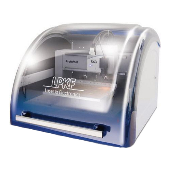
Page 11: Product Description
The ProtoMat S is controlled using the easy to operate software CircuitPro. Moreover the software is able to import several CAD formats and to generate production data from these files. Fig. 1: ProtoMat S series © 2011 LPKF AG HB V0.9/Mrz-11... -
Page 12: Type Label
If any questions occur concerning identification of your machine and the corresponding equipment please always quote the serial number according to the type label to the LPKF service. Fig. 2: Type plate /1/ Machine type /4/ Operating voltage... -
Page 13: Accessories
Hard disk 2 GB free space on internal disk Graphic board NVIDEA with at least 512 MB graphics memory Screen resolution 1280 x 1024 / High Colour (16 Bit) Monitor 17“ VGA colour monitor © 2011 LPKF AG HB V0.9/Mrz-11... -
Page 14: Dust Extraction
20,000 Pa Connecting adapter Ø 50 mm Sound level 62 dB (A) Collection efficiency > 98 % Power consumption 1.1 kW We recommend using a dust extraction unit type LPKF Air Management System. Note © 2011 LPKF AG HB V0.9/Mrz-11... -
Page 15: Manufacturer
ProtoMat S Product description Pos: 4 /ED_Technische_Dokumentation/2_Bedienungsanleitung/Maschine/RP_Fräsbohrplotter/ProtoMat_S_Serie/ProtoMat_S_Serie_IIG/Kapitel_1_Produktbeschreibung/1_4_Hersteller @ 0\mod_1255007908120_2058.docx @ 3741 @ 2 1.4 Manufacturer LPKF LPKF Laser & Electronics AG Osteriede 7 D-30827 Garbsen Germany Phone +49 (0)5131 - 70 95 – 0 +49 (0)5131 - 70 95 - 90 Email info@lpkf.com... -
Page 16: Ec Declaration Of Conformity
1.5 EC declaration of conformity 1.5.1 ProtoMat S43 EC declaration of conformity in accordance with machinery directive 2006/42/EG, Appendix II A The manufacturer/seller LPKF Laser & Electronics AG Osteriede 7 30827 Garbsen Germany hereby declares that the following product Product name... - Page 17 Product description The following EC guidelines are applied: • EMC guideline 2004/108/EG • Directive 2006/95/EC relating to electrical equipment designed for use within certain voltage limits Location: Garbsen Date: 28. March 2011 Bernd Lange (CTO) © 2011 LPKF AG HB V0.9/Mrz-11...
-
Page 18: Protomat S63
ProtoMat S 1.5.2 ProtoMat S63 EC declaration of conformity in accordance with machinery directive 2006/42/EG, Appendix II A The manufacturer/seller LPKF Laser & Electronics AG Osteriede 7 30827 Garbsen Germany hereby declares that the following product Product name LPKF ProtoMat S63... - Page 19 Product description The following EC guidelines are applied: • EMC guideline 2004/108/EG • Directive 2006/95/EC relating to electrical equipment designed for use within certain voltage limits Location: Garbsen Date: 28. March 2011 Bernd Lange (CTO) © 2011 LPKF AG HB V0.9/Mrz-11...
-
Page 20: Protomat S103
ProtoMat S 1.5.3 ProtoMat S103 EC declaration of conformity in accordance with machinery directive 2006/42/EG, Appendix II A The manufacturer/seller LPKF Laser & Electronics AG Osteriede 7 30827 Garbsen Germany hereby declares that the following product Product name LPKF ProtoMat S103... - Page 21 Product description The following EC guidelines are applied: • EMC guideline 2004/108/EG • Directive 2006/95/EC relating to electrical equipment designed for use within certain voltage limits Location: Garbsen Date: 28. March 2011 Bernd Lange (CTO) © 2011 LPKF AG HB V0.9/Mrz-11...
- Page 22 Product description ProtoMat S © 2011 LPKF AG HB V0.9/Mrz-11...
-
Page 23: Safety Notes
Any accidental starting of the motor and moving of the mill/drill head during repairs and servicing may cause considerable injuries. ATTENTION Make sure that only one person operates the machine. Secure the machine during servicing and repair activities appropriate. © 2011 LPKF AG HB V0.9/Mrz-11... - Page 24 Risk of injury! An instable level surface can collapse and hurt the operator during machining of a work piece due to vibrations and the machine powers. ATTENTION The machine must be placed on a solid surface. © 2011 LPKF AG HB V0.9/Mrz-11...
-
Page 25: General Safety Notes
Read the operation manual before start up the machine and any usage of the machine. Contact the LPKF service if any problems occur! The machine must exclusively be operated, repaired and serviced by qualified and authorised staff. - Page 26 Safety notes ProtoMat S © 2011 LPKF AG HB V0.9/Mrz-11...
-
Page 27: Functional Description
Permitted machining materials For reliable and safe operation of the circuit board plotter ProtoMat S we recommend original LPKF consumables. These articles are available with good value as multilayer sets or they are sold as single material for the different applications. -
Page 28: Equipment Design
3.2 Equipment design ProtoMat S series circuit board plotters are constructed equally in principle to facilitate upgrades as simple as possible. 3.2.1 Housing Fig. 3: Front view /1/ Soundproof housing /2/ Cover knob /3/ Soundproof cover © 2011 LPKF AG HB V0.9/Mrz-11... - Page 29 ProtoMat S Functional description Fig. 4: Back view /1/ Interfaces /2/ Suction pipe with connector for extraction tube Fig. 5: Interfaces /1/ USB port /2/ LPKF ports (4 x SUB-D, 25 pin.) © 2011 LPKF AG HB V0.9/Mrz-11...
-
Page 30: Working Area
ProtoMat S 3.2.2 Working area Fig. 6: Working table /1/ Mill/drill head /2/ Working table Fig. 7: Vacuum table /1/ Mill/drill head /4/ Connector /2/ Vacuum table /5/ Pressure meter /3/ Vacuum control unit © 2011 LPKF AG HB V0.9/Mrz-11... -
Page 31: Mill/Drill Head
/1/ Status LED /4/ Milling depth adjustment (manual) /2/ Manual Z direction adjustment /5/ Open/close collet chuck (manual) /3/ Tool holder Tab. 5: LED Signal signalling The circuit board plotter is ready for operation. ProtoMat S43 © 2011 LPKF AG HB V0.9/Mrz-11... -
Page 32: Mill/Drill Head
Fig. 9: Mill/drill head ProtoMat S63/S103 /1/ Status LED /2/ Tool holder /3/ Camera Tab. 2: LED Signal signalling The circuit board plotter is ready for operation. ProtoMat S63/ S103 Flash The collet chuck is moving. © 2011 LPKF AG HB V0.9/Mrz-11... - Page 33 ProtoMat S Functional description Fig. 10: Tool holder unit /1/ Tool holder /2/ Tool (e. g. Spiral drill 0.2 mm) Fig. 11: Camera /1/ Camera /3/ Connector for dispenser /2/ Ring light /4/ Objective © 2011 LPKF AG HB V0.9/Mrz-11...
-
Page 34: Conditions Of Use
The circuit board plotter may only be operated using the delivered control software CircuitPro. Please contact the LPKF service at once if you wish to use an other control software as the delivered item! Note The circuit board plotter may only be start up with a sufficient dust extraction and a fine particle filtering. -
Page 35: Disclaimer
Any processing of bodily parts (e.g. fingernails) is not allowed. Always contact the LPKF service first if you are not sure if the used materials can be processed with the circuit board plotter. -
Page 36: Technical Data
Functional description ProtoMat S Pos: 11 /ED_Technische_Dokumentation/2_Bedienungsanleitung/Maschine/RP_Fräsbohrplotter/ProtoMat_S_Serie/ProtoMat_S_Serie_IIG/Kapitel_3_Funktionsbeschreibung/3_4_Technische_Daten @ 0\mod_1254740954986_2058.docx @ 3612 @ 2333 3.4 Technical Data 3.4.1 ProtoMat S43 Technical data circuit board plotter type ProtoMat S43: Tab. 6: Technical Data Values data ProtoMat Mains power supply Voltage range from 110 to 240 V AC, 50 - 60 Hz... -
Page 37: Protomat S63
305 x 229 x 25 mm (X x Y x Z) Resolution (X/Y) +/- 0.25 µm (0.01 Mil) Repeat accuracy +/- 5 µm (0.2 Mil) Exactness reference hole system +/- 20 µm (0.8 Mil) Minimal drill diameter 0.2 mm © 2011 LPKF AG HB V0.9/Mrz-11... -
Page 38: Protomat S103
305 x 229 x 25 mm (X x Y x Z) Resolution (X/Y) +/- 0.25 µm (0.01 Mil) Repeat accuracy +/- 5 µm (0.2 Mil) Exactness reference hole system +/- 20 µm (0.8 Mil) Minimal drill diameter 0.2 mm © 2011 LPKF AG HB V0.9/Mrz-11... -
Page 39: Emissions
Local laws, directions and regulations as well as company directions concerning waste of material (fine particles and rest materials) have to be obeyed. Check disposal with the responsible employee of your company e.g. your environmental protection representative. © 2011 LPKF AG HB V0.9/Mrz-11... - Page 40 Functional description ProtoMat S © 2011 LPKF AG HB V0.9/Mrz-11...
-
Page 41: Transport And Storage
At longer down or storage times, transport locks have to be installed and the circuit board plotters has to be stored in its covering box. Store the circuit board plotter in a cool and dry location. Use a protective cover to protect it from dust and humidity. © 2011 LPKF AG HB V0.9/Mrz-11... - Page 42 Transport and storage ProtoMat S © 2011 LPKF AG HB V0.9/Mrz-11...
-
Page 43: Installation
/1/ Dust extraction /3/ PC /2/ Circuit board plotter The areas marked in red are safety zones that must not be blocked with objects. Pos: 17 /ED_Technische_Dokumentation/2_Bedienungsanleitung/Maschine/RP_Fräsbohrplotter/ProtoMat_S_Serie/ProtoMat_S_Serie_IIG/Kapitel_5_Installation_Inbetriebnahme/5_2_Gerät_auspacken @ 0\mod_1254753807408_2058.docx @ 3639 @ 2 © 2011 LPKF AG HB V0.9/Mrz-11... -
Page 44: Unpacking The Device
Installation The installation of the circuit board plotter must be done in four steps: Removal of the transport locks Connection of the mains cable III. Connection of the dust extraction Connection of the PC © 2011 LPKF AG HB V0.9/Mrz-11... -
Page 45: Remove The Transport Lock
Removal of the transport locks Take a side cutter and open the security tape /2/. Remove the security tape /2/ and dispose it. Remove the foam mat /1/. ♦ The transport locks are removed. © 2011 LPKF AG HB V0.9/Mrz-11... -
Page 46: Connecting The Circuit Board Plotter
Guide the mains voltage cable alongside the machine through the gap of the machine housing. Connect the circuit board plotter with the mains power supply. Connect the PC with the mains power supply. Connect the monitor with the mains power supply. © 2011 LPKF AG HB V0.9/Mrz-11... -
Page 47: Commissioning
Activate the circuit board plotter by setting the main switch to position I (ON). Close the cover. Start CircuitPro. ➨ The CircuitPro start-up logo is displayed: Fig. 15: Start-up Logo ♦ The circuit board plotter is ready. © 2011 LPKF AG HB V0.9/Mrz-11... -
Page 48: Remove The Dummy Tool
For machines with automatic lock: - The software open the collet chuck automatically. ➨ The tool holder release the dummy tool. Remove the dummy tool. ♦ Now the circuit board plotter is ready for operation. © 2011 LPKF AG HB V0.9/Mrz-11... -
Page 49: Operation
Phase III System shut down The control software CircuitPro has to be terminated and the circuit board plotter, the PC and the dust extraction must switched off. © 2011 LPKF AG HB V0.9/Mrz-11... -
Page 50: Start System
Start the PC by setting the main switch to position 1 (ON). Enter user name and password. Wait until the operation system has booted the user interface. Go to the task bar and click on Start>Programs>LPKF Laser & Electronics>CircuitPro. ➨ The CircuitPro start-up logo is shown: Fig. -
Page 51: Tool Status Monitoring
The drill/mill head moves to the zero position, if the value “0“ is entered in the input field \Tool holder ID\. The message “Open collet chuck“ is shown. Click [OK] to eject the tool. Note ♦ The tool is placed in the tool holder. © 2011 LPKF AG HB V0.9/Mrz-11... -
Page 52: Grafical User Interface
Insert The window “Navigation“ displays the actual Window working area. Navigation The window “CAM View“ shows the project data. CAM View The individual objects are highlighted in user defined colours. © 2011 LPKF AG HB V0.9/Mrz-11... -
Page 53: Menu Bar
Use the functions of the menu “Operate“ to control the machining process. Camera The menu “Camera” offers program functions to set the installed camera. Extras The menu “Extras” offers functions to customize CircuitPro. Help The menu “Help“ gives information about this program. © 2011 LPKF AG HB V0.9/Mrz-11... -
Page 54: Function Bar
Change the main window. The user can switch over from CAM view to machining view. Insert Several object functions. Edit Several tool path functions. Standard General program functions e.g. Open, Save, Import/Export and Print. © 2011 LPKF AG HB V0.9/Mrz-11... -
Page 55: Window Processing
The connected circuit board plotter is controlled via the menu window “Processing“: Fig. 22: Window Processing /1/ Mill/drill head manual control functions /4/ Register /2/ Select head /5/ Moving to determined positions /3/ Processing functions /6/ Mill/drill head control © 2011 LPKF AG HB V0.9/Mrz-11... -
Page 56: Manual Control Of The Mill/Drill Head
[+Z] to lift up the mill/drill head. The output field \R:\ displays the current spindle rotation speed of the mill/drill head. The output fields \X:\, \Y:\ and \Z:\ show the current position of the mill/drill head. © 2011 LPKF AG HB V0.9/Mrz-11... -
Page 57: Select Head
Click [Mill/drill head] to move the mill/drill head (with mounted tool) to the current camera position. Click [Camera] to move the mill/drill head (with camera) to the current tool position. Click [Dispenser] to move the mill/drill head (with Dispenser) to © 2011 LPKF AG HB V0.9/Mrz-11... -
Page 58: Operate
Select a machining phase and mark the machining area with the mouse. Click [Start processing select area] to start processing of the machining phase within the selected area. Click [Stop processing] to stop the current machining process. © 2011 LPKF AG HB V0.9/Mrz-11... -
Page 59: Move To Position
Click [Move by mouse position] and the mill/drill head follows the current mouse position. Click [Pause Position] to move the mill/drill head to the pause position. Click [Zero Position] to move the mill/drill head to the zero position (reference point). © 2011 LPKF AG HB V0.9/Mrz-11... -
Page 60: Head Actions
The symbol changes correspondingly from a green triangle (90° position) to a red rectangle. Click [Exhaust unit on/off] to activate/deactivate the exhaust unit by operator. The symbol changes correspondingly from a green triangle (90° position) to a red rectangle. © 2011 LPKF AG HB V0.9/Mrz-11... -
Page 61: Establish A Connection
Go to the menu “Machining“ and click “Connect…”. ➨ The following window is shown: Fig. 29: Connect Click on the selection box \Machine type\ and select the type of the connected machine. Click [Connect]. © 2011 LPKF AG HB V0.9/Mrz-11... - Page 62 ➨ After the circuit board plotter was detected and its data will be transmitted, the CircuitPro user interface opens: Fig. 31: User interface ♦ Now the circuit board plotter is ready for operation. Pos: 24 /ED_Technische_Dokumentation/2_Bedienungsanleitung/Maschine/RP_Fräsbohrplotter/ProtoMat_S_Serie/ProtoMat_S_Serie_IIG/Kapitel_6_Bedienung/6_04_Material_auflegen @ 0\mod_1255676413949_2058.docx @ 3960 @ 2 © 2011 LPKF AG HB V0.9/Mrz-11...
-
Page 63: Place Material
Fix the production material with a tape on the underlay. The tape has to be removable without remains. The tape has to be guided alongside the edges. ♦ The production material is fixed. Pos: 25 /ED_Technische_Dokumentation/2_Bedienungsanleitung/Maschine/RP_Fräsbohrplotter/ProtoMat_S_Serie/ProtoMat_S_Serie_IIG/Kapitel_6_Bedienung/6_05_Werkzeug_einrichten @ 0\mod_1255676504814_2058.docx @ 3964 @ 23 © 2011 LPKF AG HB V0.9/Mrz-11... -
Page 64: Tool Setup
The tool magazine of the circuit board plotter can house up to 15 different tools. The position of each tool is displayed in the window “Machining view“. Fig. 33: Machining view /1/ Tool position /3/ Axis of refexion /2/ Machining area /4/ Current mill/drill head position © 2011 LPKF AG HB V0.9/Mrz-11... - Page 65 Select a free position of the entry field \Tools\ and specify the tool. A selection of supported tools can be found in the list “required tools“. Note Click [Apply]. ♦ Now the tool is configured. © 2011 LPKF AG HB V0.9/Mrz-11...
-
Page 66: Tool Colour Code
Operation ProtoMat S 6.5.1 Tool colour code All LPKF tools are equipped with a distance ring, colour coded accordingly to the tool applications: Tab. 12: Tool Colour Tool application colour coding MicroCutter Orange UniversalCutter Blue EndMill (RF) Purple EndMill Olive-green... -
Page 67: Manual Drilling
Risk of injury! The used tools are sharp-edged and cause cut or stab wounds when used improperly. ATTENTION Store the tools always in the toolbox and secure the toolbox against unauthorised utilisation. © 2011 LPKF AG HB V0.9/Mrz-11... - Page 68 Type a value into the input filed \X/Y step size\ and click[+X], [-X], [+Y] or [-Y] until the drilling position is reached. The exact position is displayed in the output fields \X:\ and \Y:\. Fig. 39: Control milling/drilling head Click on [motor on/off]. © 2011 LPKF AG HB V0.9/Mrz-11...
- Page 69 Click on [Motor on/off]. ➨ The drilling spindle stops and the dust extraction is deactivated. Repeat steps 3 to 6 if you wish to create further drilling holes. ♦ The drilling hole is created. © 2011 LPKF AG HB V0.9/Mrz-11...
-
Page 70: Manual Milling
Risk of injury! During the machining process the used tools and the collet chuck heat up, direct contact may cause burnings. ATTENTION Wear protective gloves and tweezers for manual change of tools during operation. © 2011 LPKF AG HB V0.9/Mrz-11... - Page 71 ProtoMat S Operation Risk of injury! The used tools are sharp-edged and cause cut or stab wounds when used improperly. ATTENTION Store the tools always in the toolbox and secure the toolbox against unauthorised utilisation. © 2011 LPKF AG HB V0.9/Mrz-11...
- Page 72 Produce a test track. Check the result using a measuring microscope. Fig. 41: Optimal milling depth Repeat the process in necessary until a sufficient amount of material has been removed. ♦ The milling depth is now adjusted. © 2011 LPKF AG HB V0.9/Mrz-11...
- Page 73 Fig. 43: Set position Click[+X], [-X], [+Y] or [-Y] until the start position is reached. The exact position is displayed in the output field \X:\ and \Y:\. Fig. 44: Milling/drilling head control Click on [Motor on/off]. © 2011 LPKF AG HB V0.9/Mrz-11...
- Page 74 Click on [Motor on/off]. ➨ The drilling spindle stops and the dust extraction will be deactivated. For further milling tracks you have to repeat the steps 3 to 8. ♦ Now the milling path is produced. © 2011 LPKF AG HB V0.9/Mrz-11...
-
Page 75: Automatic Mode
Risk of injury! The used tools are sharp-edged and cause cut or stab wounds when used improperly. ATTENTION Store the tools always in the toolbox and secure the toolbox against unauthorised utilisation. © 2011 LPKF AG HB V0.9/Mrz-11... -
Page 76: Specify Production Type
Fig. 45: Start wizard Click Wizards>Process planning wizard…. ➨ The following window is shown: Fig. 46: Process planning wizard Edit the required setting for the production process and click [Next]. Follow the instructions of the assistant. © 2011 LPKF AG HB V0.9/Mrz-11... - Page 77 ProtoMat S Operation ➨ If all settings have been made the following window is shown: Fig. 47: Summary Click [Done] and the window will be closed. ♦ Now the production process is configured. © 2011 LPKF AG HB V0.9/Mrz-11...
-
Page 78: Loading The Cbf File
Click on the CBF file. ➨ The file name appears in the selection field \File name\. Click [Open]. ➨ The CBF file is loaded and the projects contained are placed on the working area. © 2011 LPKF AG HB V0.9/Mrz-11... - Page 79 ProtoMat S Operation Fig. 49: Working area /1/ Working area /2/ PCB data ♦ Now the CBF file is loaded. © 2011 LPKF AG HB V0.9/Mrz-11...
-
Page 80: Production Of The Printed Circuit Board
Click Wizard>Board Production Wizard. ➨ The following window is shown: Fig. 51: Process planning wizard Follow the instructions and click [Start]. ➨ The next production step is shown. Follow the instructions and click [Next]. © 2011 LPKF AG HB V0.9/Mrz-11... - Page 81 Fig. 52: Process planning wizard Click [Finish] to stop the board production process. Demount the board. Clean the board and make a visual check. ♦ The board production is finished. © 2011 LPKF AG HB V0.9/Mrz-11...
-
Page 82: Dispense
/1/ Dispense adapter /3/ Dispensing tip /2/ Empty cartridge /4/ Solder Paste cartridge A plastic hose to connect the dispense device to the compressed air system is also included in the delivery. © 2011 LPKF AG HB V0.9/Mrz-11... -
Page 83: Mount Dispense Set
Take the solder paste cartridge and unscrew the lower end cap. Screw the dispensing tip on the outlet opening of the solder paste cartridge. Insert the solder paste cartridge into the dispense adapter and tighten the upper fastening nut carefully. Fig. 55: Installed dispense set © 2011 LPKF AG HB V0.9/Mrz-11... -
Page 84: Dispense Process
➨ The following window is shown: Fig. 56: Window Dispense Use the default values or enter new dispense parameters for the current project. Click [Run]. ➨ The program is assigning the solder paste points. Click on Wizards>Dispense preparation wizard. © 2011 LPKF AG HB V0.9/Mrz-11... - Page 85 ➨ After all processing steps have been carried out the following window is shown: Fig. 58: Dispense preparation wizard finished Click [Done]. ➨ The dispense preparation is finished. Click on Wizards>Dispensing wizard. ➨ The wizard is starting and the following window is shown: © 2011 LPKF AG HB V0.9/Mrz-11...
- Page 86 Follow the instructions and click [Next]. ➨ After all processing steps have been carried out the following window is shown: Fig. 60: Dispensing wizard finished Click [Finish]. ♦ The dispensing process is finished. © 2011 LPKF AG HB V0.9/Mrz-11...
-
Page 87: Shutdown The System
Click File>Save. ♦ The production data was saved by using the current file name. ■ Saving a new CBF file Click File>Save as…. ➨ The window “Save as…” is shown: Fig. 61: Save as… © 2011 LPKF AG HB V0.9/Mrz-11... -
Page 88: Exit Circuitpro
■ Switch off the dust extraction Turn the main switch of the dust extraction to position OFF (0). ♦ The dust extraction is switched off. Pos: 31 /ED_Technische_Dokumentation/2_Bedienungsanleitung/Maschine/RP_Fräsbohrplotter/ProtoMat_S_Serie/ProtoMat_S_Serie_IIG/Kapitel_7_Fehlerbeseitigung/7_1_Fehlerbeseitigung @ 0\mod_1254844173282_2058.docx @ 3660 @ 1 © 2011 LPKF AG HB V0.9/Mrz-11... -
Page 89: Troubleshooting
This chapter gives some information concerning correction of small faults that may occur during operation of the circuit board plotter. Please contact the LPKF service if the measures described in this chapter do not provide the desired success. LPKF is not liable for improper repairs! Note Tab. - Page 90 Troubleshooting ProtoMat S © 2011 LPKF AG HB V0.9/Mrz-11...
-
Page 91: Maintenance/Servicing
Open the hood and check the mill/drill head and the working table for visible damages. ➨ Contact the LPKF service immediately whenever you find a damage and make sure that the circuit board plotter is not used until the damage is removed. -
Page 92: Maintenance
100 operating cleaning service plan hours Chucks after 100 operating cleaning hours Tool position Tool is not put down Configure tool position correctly Dust extraction Extraction power Exchange fine particle filter decreases perceptible © 2011 LPKF AG HB V0.9/Mrz-11... -
Page 93: Storage
Place the covering box besides the work desk. Open the box cover and take the unpacking instruction. Follow the unpacking instruction step by step in reverse direction. ♦ Now the circuit board plotter is packed. © 2011 LPKF AG HB V0.9/Mrz-11... -
Page 94: Disposal
Now the circuit board plotter is stored. 9.2.1 Disposal Legal regulations and directives concerning disposal of electric devices and machines have to be observed. Note Dispose of the circuit board plotter must be done according to legal directives. © 2011 LPKF AG HB V0.9/Mrz-11... -
Page 95: Appendix
Spiral Drill, cylindrical, 1/8“ 1,00 115 855 Spiral Drill, cylindrical, 1/8“ 1,10 115 856 Spiral Drill, cylindrical, 1/8“ 1,20 115 857 Spiral Drill, cylindrical h, 1/8“ 1,30 115 858 Spiral Drill, cylindrical, 1/8“ 1,40 115 859 © 2011 LPKF AG HB V0.9/Mrz-11... -
Page 96: Tool Set 1/8
2,40 115 869 Spiral Drill, cylindrical, 1/8“ 2,95 115 870 Spiral Drill, cylindrical, 1/8“ 3,00 115 871 Furthermore LPKF offers tool sets. 10.1.1.1 Tool set 1/8“ Order code: 115 909 Tab. 17: Tool set Tool specification Length Ø Quan- 1/8“... -
Page 97: Hf And Micro Wave Tool Set 1/8
3 mm Base material FR4 229 x 305 x 1,5 35/35 115 970 reference holes 3 mm Base material FR4 229 x 305 x 1,5 115 971 reference holes 3 mm and protective foil © 2011 LPKF AG HB V0.9/Mrz-11... -
Page 98: Multilayer-Material
229 x 305 x 0,2 -/18 119 818 without protective foil for ProConduct Pressing plate with 229 x 205 x 1,6 120 345 reference holes Press cushion with 229 x 305 x 1,7 120 999 reference holes © 2011 LPKF AG HB V0.9/Mrz-11... -
Page 99: Glossary
Coatings which mask off and surface insulate those areas mask of a circuit where soldering is not desired. Throughplating An electrical connection between conductive patterns on opposite sides of an insulating base, e.g. plated-through hole or clinched jumper wire. © 2011 LPKF AG HB V0.9/Mrz-11... -
Page 100: List Of Figures
Fig. 5: Interfaces ....................27 Fig. 6: Working table ..................28 Fig. 7: Vacuum table ..................28 Fig. 8: Mill/drill head ProtoMat S43 ..............29 Fig. 9: Mill/drill head ProtoMat S63/S103 ............30 Fig. 10: Tool holder unit ..................31 Fig. - Page 101 Fig. 57: Start Dispense preparation wizard ............83 Fig. 58: Dispense preparation wizard finished ..........83 Fig. 59: Start Dispensing wizard ................ 84 Fig. 60: Dispensing wizard finished ..............84 Fig. 61: Save as… ..................... 85 © 2011 LPKF AG HB V0.9/Mrz-11...
-
Page 102: List Of Tables
Tab. 3: PC data ....................11 Tab. 2: Data for dust extraction ................. 12 Tab. 4: Machining materials ................25 Tab. 5: LED signalling ProtoMat S43 ..............29 Tab. 2: LED signalling ProtoMat S63/ S103 ............30 Tab. 6: Technical data ProtoMat S43 ..............34 Tab. -
Page 103: Index
CPU 11 HF tool set 11 depth of penetration 68 home-position 57 Dielectric 97 humidity 39 Dispense 97 import work file 51 dispense adapter 81, 82 installation 33, 41, 42 Dispense adapter 80 interface 44 © 2011 LPKF AG HB V0.9/Mrz-11... - Page 104 OS 45 lift truck 42, 92 password 45, 48 LPKF port 27 pause position 57, 61 LPKF service 10, 23, 32, 33, 89 PC 41, 42, 44, 45, 85, 86 LPKF-Service 87 PCB 73 machine 21, 23, 41 PCB material 66, 71...
- Page 105 42, 91 tape 61 work file 51 Technical data ProtoMat S103 36 work piece 21, 41 Technical data ProtoMat S43 34 work protection measure 37 Technical data ProtoMat S63 35 work space 23 technical information 33 working area 50, 51, 76...
Need help?
Do you have a question about the ProtoMat S43 and is the answer not in the manual?
Questions and answers