Table of Contents
Advertisement
Advertisement
Table of Contents

Related Manuals for iControl iCamera2

Summary of Contents for iControl iCamera2
- Page 1 User’s Guide...
-
Page 2: Table Of Contents
Table of Contents CHAPTER 1 INTRODUCTION ..................1 Overview ........................1 Physical Details - iCamera2 ..................3 Package Contents ......................5 CHAPTER 2 BASIC SETUP ....................6 System Requirements ....................6 Installation - iCamera2 ....................6 Wall Mounting ......................9 CHAPTER 3 VIEWING LIVE VIDEO ................ - Page 3 APPENDIX A SPECIFICATIONS ..................64 iCamera2 ........................64 Regulatory Approvals ....................64 Copyright © 2014. All Rights Reserved. Document Version: 1.0 All trademarks and trade names are the properties of their respective owners.
-
Page 4: Chapter 1 Introduction
The Motion Detection feature can also have its own schedule, so it is active only when required. • Syslog Support. If you have a Syslog Server, the iCamera2 can send its log data to your Syslog Server. • Audio Support. -
Page 5: Internet Features
Internet Features • User-definable HTTP/HTTPS port number . This allows Internet Gateways to use "port mapping" so the iCamera2 and a Web Server can share the same Internet IP address. • NTP (Network-Time-Protocol) Support. NTP allows the iCamera2 to calibrate its internal clock from an Internet Time-Server. -
Page 6: Physical Details - Icamera2
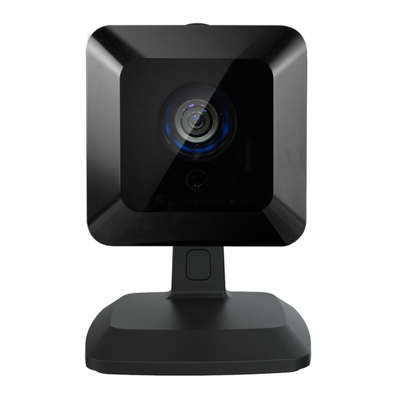
Physical Details - iCamera2 Front - iCamera2 Figure 1: Front Panel 1. Light Sensor This is hardware sensor to detect LUX. 2. Lens No physical adjustment is required or possible for the lens, but you should ensure that the lens cover remain clean. The image quality is degraded if the lens cover is dirty or smudged. - Page 7 Rear - iCamera2 Figure 2: Rear Panel 1. LAN Port Use standard Ethernet cable (RJ45 connectors) to connect your PC to the port for installation and configuration. The port is also used for power connection when the camera is under wireless mode. A customized PoE (Power over Ethernet) splitter, as a Y-cable, for both Ethernet and DC Jack is provided.
-
Page 8: Package Contents
Package Contents The following items should be included: If any of these items are damaged or missing, please contact your dealer immediately. 1. iCamera2 x 1 2. Stand x 1 3. Y-cable x 1 4. DC Cable x 1 5. Ethernet Cable x 1 6. -
Page 9: Chapter 2 Basic Setup
Installation - iCamera2 Step 1 - Initial Setup Initial setup is required when the iCamera2 is used for the FIRST time. It only needs to be done ONCE in order to configure the wireless settings for the iCamera2. Note: Skip this section if the iCamera2 has been set up already. - Page 10 1. Assemble the Camera Hold the metal screw of the stand up. Face the back of the iCamera2 to the stand and turn the iCamera2 clockwise to attach it to the stand. 2. Connect the Y-cable Connect the provided Y-cable (with Ethernet) to the LAN port of iCamera2.
-
Page 11: Connect The Ethernet Cable
3. Power Up Connect the DC cable to the Ethernet cable. Connect the supplied power adapter to the DC cable to power up the iCamera2. Use only the power adapter provided. Using a different one may cause hardware damage. 4. Check the LEDs •... -
Page 12: Wall Mounting
3. Attach the stand to the plate. 4. Connect the LAN cable into the LAN port of the device. Turn the iCamera2 clockwise to attach it to the stand. 5. Connect the other end of the LAN cable to the adapter through the holes of the stand. -
Page 13: Chapter 3 Viewing Live Video
Router must be configured correctly. See Making Video available from the Internet in Chapter 4 - Advanced Viewing Setup for details. Requirements To view the live video stream generated by the iCamera2, you need to meet the following requirements: •... - Page 14 5. If the Administrator has restricted access to known users, you will then be prompted for a username and password. Enter the name and password assigned to you by the iCamera2 administrator. 6. The first time you connect to the camera, you will be prompted to install decoders.
-
Page 15: Connecting To A Camera Via The Internet
Also, you need a broadband Internet connection to view video effectively. Dial-up connections are NOT supported. To establish a connection from your PC to the iCamera2 via the Internet: 1. Obtain the following information from the Administrator of the camera you wish to connect to: •... - Page 16 6. If the Administrator has restricted access to known users, you will then be prompted for a username and password. Enter the name and password assigned to you by the iCamera2 administrator. 7. The first time you connect to the camera, you will be prompted to install decoders.
-
Page 17: Viewing Live Video
Viewing Live Video After installing the decoders, you will be able to view the live video stream in its own window, as shown below. Figure 7: View Video Screen There are a number of options available on this screen, accessed by select list, button or icon. See the table below for details. -
Page 18: General Options
General Options These options are always available, regardless of the type of camera you are connected to. Streaming. Use this drop-down list to select the desired streaming. Full Size. When using high-resolution mode (1280*720), click this button to see the full size of the image. Select the desired option from the drop-down list. -
Page 19: Chapter 4 Advanced Viewing Setup
If necessary, the iCamera2 Administrator can adjust the Video image. To Adjust the Video Image: 9. Connect to the Web-based interface of the iCamera2. (See Chapter 5 - Web-based Management for details.) 10. Select Administration, then Streamings. You will see a screen like the example below. - Page 20 Select the default channel for streaming from the drop-down list. Default Streaming Channel Streaming 1 Settings Video Format Select the desired format from the list. Select the desired video resolution format. Resolution • Constant Bit Rate: Select the desired bit rate. The default is set Video Quality to 2.0 Mbps.
- Page 21 User Defined URI You may enter the URI up to 32 characters long for accessing the live video from camera through cell phone connection.
-
Page 22: Controlling User Access To The Video Stream
Controlling User Access to the Video Stream By default, anyone can connect to the iCamera2 and view live Video at any time. If desired, you can limit access to scheduled times, and also restrict access to known users. To Control User Access to Live Video: 1. -
Page 23: Making Video Available From The Internet
Normally, HTTP (Web) connections use port 80. Since the iCamera2 uses HTTP, but port 80 is likely to be used by a Web Server, you can use a different port for the iCamera2. This port is called the Secondary Port. -
Page 24: Viewing Live Video Via The Internet
Enter the Internet address of the Router/Gateway, and its port number, in the Address (or Location) field of your Browser. Example - IP address: HTTP://203.70.212.52:1024 Where the Router/Gateway's Internet IP address is 203.70.212.52 and the "Secondary Port" number on the iCamera2 is 1024. -
Page 25: Motion Detection Alerts
Motion Detection Alerts The Motion Detection feature can generate an Alert when motion is detected. The iCamera2 will compare consecutive frames to detect changes caused by the movement of large objects. But the motion detector can also be triggered by: •... -
Page 26: Chapter 5 Web-Based Management
This Chapter provides Setup details of the iCamera2’s Web-based Interface. This Chapter is for the Camera Administrator only. Introduction The iCamera2 can be configured using your Web Browser. The iCamera2 must have an IP address which is compatible with your PC. Connecting to iCamera2 •... -
Page 27: Welcome Screen
Welcome Screen When you connect, the following screen will be displayed. Figure 13: Welcome Screen The menu options available from this screen are: • View Video - View live Video using your Web Browser. See Chapter 3 - Viewing Live Video for details. -
Page 28: Administration Menu
Administration Menu Clicking on Administration on the menu provides access to all the settings for the iCamera2. The Administration menu contains the following options: Setup • System • Network • Wireless • DDNS • IP Filter Video & Audio •... -
Page 29: System Screen
After clicking Administration on the main menu, or selecting System on the Administration menu, you will see a screen like the example below. Figure 14: System Screen Data - System Screen System Settings This displays the ID for the iCamera2. Device ID Enter the desired name for the iCamera2. Camera Name Description This field is used for entering a description, such as the location of the iCamera2. - Page 30 Enable or disable the Time Server feature as required. Network Time Protocol If Enabled, the iCamera2 will contact a Network Time Server at regular intervals and update its internal timer. Enter the address for the desired NTP server. NTP Server...
-
Page 31: Network Screen
Network Screen This screen is displayed when the Network option is clicked. Figure 15: Network Screen... - Page 32 Username - The user name (or account name) provided by your ISP. • Password - Enter the password for the login name above. If selected, the iCamera2 will use the DNS address or addresses Obtain DNS server address provided by the DHPC server.
- Page 33 The Time to Live you entered must be in-between 1 to 255. UPnP Enable Discovery If enabled, the iCamera2 will broadcast its availability through UPnP. UPnP compatible systems such as Windows XP will then be able to detect the presence of the iCamera2.
- Page 34 If enabled, HTTP connections (from your Web Browser) can use secondary port instead of port 80 (the standard HTTP port) to access the camera. Bonjour If enabled, the iCamera2 can be accessed through a "Bonjour" Enable Bonjour enabled browser, such as Microsoft Internet Explorer (with a Service Bonjour plug-in) or Safari browser.
-
Page 35: Wireless Screen
Select your region from the drop-down list. Domain • Channel No. In Infrastructure mode, this setting is ignored. The iCamera2 will use the Channel set on the Access Point. • For Ad-hoc mode, select the Channel you wish to use on your iCamera2. - Page 36 Security Security System Select the desired option, and then enter the settings for the selected method: • Disabled - No security is used. Anyone using the correct SSID can connect to your network. This is default. • WEP - The 802.11b standard. Data is encrypted before transmission, but the encryption system is not very strong.
- Page 37 WPA Personal Shared Key Enter the key value. Data is encrypted using a key derived from the network key. Other Wireless Stations must use the same network key. The PSK must be from 8 to 63 characters or 64 hex characters in length.
-
Page 38: Ddns Screen
DDNS Screen Many Internet connections use a "Dynamic IP address", where the Internet IP address is allocated whenever the Internet connection is established. This means that other Internet users don't know the IP address, so can't establish a connection. DDNS is designed to solve this problem, as follows: •... - Page 39 Enter the login name for the DDNS account. Account/E-Mail Password/Key Enter the password for the DDNS account. Set the schedule for checking if the Internet IP address has Check WAN IP Address changed. If the IP address has changed, the DDNS Server will be notified.
-
Page 40: Ip Filter
IP Filter The IP Filter feature allows administrator to control Full HD IP Camera access by filtering IP addresses. This screen is displayed when the IP Filter menu option is clicked. Figure 18: IP Filter Screen Data - IP Filter Screen IP Filter IP Filter Select the desired method to perform the IP address (or addresses) -
Page 41: Streamings
Streamings This screen is displayed when the Streamings menu option is clicked. If you want to view streaming via the cell phone: 1. Cell phone should be supported by 3GPP protocol. 2. Enter 554 for RTSP port number in the Network screen. 3. - Page 42 Data - Streamings Screen Select the default channel for streaming from the drop-down list. Default Streaming Channel Streaming 1 Settings Video Format Select the desired format from the list. Select the desired video resolution format. Resolution • Constant Bit Rate: Select the desired bit rate. The default is set Video Quality to 2.0 Mbps.
- Page 43 User Defined URI You may enter the URI up to 32 characters long for accessing the live video from camera through cell phone connection.
-
Page 44: Video & Audio Screen
Select the desired option for the Saturation. You can select a value between -3 and 3. Day/Night Switch Switching Method The iCamera2 supports Day/Night mode switch for getting better quality of the low light condition. Select the desired method to use this function. IRLED Luminance... - Page 45 Options Enable Microphone Enable audio by checking this checkbox. Using Audio will increase the bandwidth requirements slightly. Audio Type Select the desired audio type. This setting will have the image swapped top-to-bottom. Flip Mirror This setting will have the image swapped left-to-right. Enable Time Stamp If enabled, the current time will be displayed on the Video image.
-
Page 46: Video Access Screen
Video Access Screen This screen is displayed when the Video Access option is clicked. Figure 21: Video Access Screen Data - Video Access Screen User Access • If disabled (default) - No login required. Users do not have to Enable Security provide a username and password when they connect to the Checking camera for viewing video. - Page 47 Add New Schedule Choose the desired option for the period. Enter the start time using a 24 hr clock. Start Time End Time Enter the end time using a 24 hr clock. Click this button to add a new period. Use this button to clear the input fields.
-
Page 48: User Database Screen
User Database Screen This screen is displayed when the User Database option is clicked. Figure 22: User Database Screen Data - User Database Screen Existing Users User List This displays all users you have entered into the User database. If you have not entered any users, this list will be empty. -
Page 49: Pan/Tilt Screen
Pan/Tilt Screen This screen is displayed when the Pan/Tilt option on the Video & Audio menu is clicked. Figure 23: Pan/Tilt Screen Data - Pan/Tilt Screen Pan/Tilt Select desired option for the patrol function. Patrol Click this button to define the preset point position. Preset Point Position Set Patrol Sequence... - Page 50 Set Preset Position Screen This screen is displayed when the Preset Point Position button on the Pan/Tilt screen is clicked. Figure 24: Preset Point Position Screen Data - Preset Point Position Goto Center Click this button to go to the center location. Go to the user defined location.
-
Page 51: Motion Detection Screen
Motion Detection Screen This screen is displayed when the Motion Detection option on the Event menu is clicked. Figure 25: Motion Detection Screen Data - Motion Detection Screen Motion Detection Motion Enable Enable this if you want to use motion detection. Note: Motion detection can be triggered by rapid changes in lighting condition, as well as by moving objects. -
Page 52: Audio Detection Screen
Audio Detection Screen This screen is displayed when the Audio Detection option on the Event menu is clicked. Figure 26: Audio Detection Screen Data - Audio Detection Screen Audio Detection Current It displays the current volume of the environment. Click Refresh to Volume update the status. -
Page 53: E-Mail Screen
E-Mail Screen This screen is displayed when the E-Mail option on the Event menu is clicked. Figure 27: E-Mail Screen Data - E-Mail Screen Primary/Secondary SMTP Server SMTP Server Enter the address of the SMTP (Simple Mail Transport Protocol) Address Server to be used to send E-Mail. -
Page 54: Ftp Screen
FTP Screen This screen is displayed when the FTP option on the Event menu is clicked. Figure 28: FTP Screen Data - FTP Screen Primary/Secondary FTP Enter the address of the FTP Server. FTP Server Port Enter the Port of the FTP Server to be connected. Enter your login name for the FTP Server. -
Page 55: Http Screen
HTTP Screen This screen is displayed when the HTTP option on the Event menu is clicked. Figure 29: HTTP Screen Data - HTTP Screen HTTP(s) Notification Enter the URL of your HTTP notification server. Enter the user name of your HTTP server. User Name Password Enter the password to match the user name above. - Page 56 Password Enter the password to match the user name above. Enter the URL of your HTTP post server. Post URL...
-
Page 57: Trigger & Recording Screen
Trigger & Recording Screen This screen is displayed when the Trigger & Recording option is clicked. Figure 30: Trigger & Recording Screen Data - Trigger & Recording Screen Event Schedule Schedule List The Event Schedule shows all of the event types currently configured in the Waterproof HD IP Camera, along with various information about their configuration, as listed below: •... - Page 58 Add a new Schedule Figure 31: Add schedule screen Enter the name of the schedule. Name Schedule Choose the desired option: Schedule • Always • Schedule • Never Trigger Event • Motion Detection - Movement in a motion detection window Trigger by can be used to trigger events.
- Page 59 • Pre/Post Capture - Select the desired length. The size of the Attachment Type file depends on this setting, and also the Video size and degree of compression.
-
Page 60: Maintenance Screen
Firmware file. Select this file. Start Click this button to start the Firmware. When the upgrade is finished, the iCamera2 will restart, and this management connection will be unavailable during the restart. Clear File Name This does NOT stop the Upgrade process if it has started. It only clears... - Page 61 Backup & Restore Backup Click Backup button to save the current configuration information to a text file. Configuration It is suggested to backup the configuration file, in order to restore the File camera easily. Click Restore button to reinitialize the camera to load the new updated Restore software.
-
Page 62: Status Screen
Data - Status Screen System Device Name This shows the name of the iCamera2. Description This shows the description of the iCamera2, such as location. The version of the current firmware installed. F/W version Network The current IP address of the iCamera2. - Page 63 Channel This shows the wireless channel currently used. The current security setting for Wireless connections. Security This shows the strength of the signal. Signal Strength Streaming (1~3) It displays the current format of video. Video Format The image size of the video stream. Resolution Video Quality This displays the image quality of the video stream.
-
Page 64: Log Screen
Log Screen This screen displays a log of system activity. Figure 34: Log Screen Data - Log Screen This is a log of system activity. System Log Click this to update the data shown on screen. Refresh Button Click this button to restart the log. Clear Log Check the box to enable the System Log Server feature. -
Page 65: Chapter 7 Troubleshooting
This chapter covers some common problems that may be encountered while using the iCamera2 and some possible solutions to them. If you follow the suggested steps and the iCamera2 still does not function properly, contact your dealer for further advice. - Page 66 The motion detection feature doesn't send me any E-mail. Problem 5 It may be that the SMTP (Simple Mail Transport Protocol) server used by Solution 5 the camera to send the E-Mail will not accept mail. (This is to prevent span being sent from the server.).
-
Page 67: Appendix A Specifications
Appendix A Specifications iCamera2 Model iCamera2 Dimensions 76.8mm (W) x 76.8mm (H) x 32.7mm (D) (without stand) Operating Temperature 0° C to 45° C Video compression H.264 and MJPEG Network Interface 1 Ethernet 10/100BaseT (RJ45) Storage Temperature -20° C to 60° C... - Page 68 C Stateme This s equipment ge enerates, uses and can radia ate radio frequ uency energy a and, if not ins stalled and use ed in acco ordance with th he instruction s, may cause h harmful interf ference to rad io communica ations.
- Page 69 IC Approvals CAN-ICES-3 (B)/ NMB-3(B) This device complies with RSS-210 of the Industry Canada Rules. Operation is subject to the following two conditions: (1) This device may not cause harmful interference, and (2) this device must accept any interference received, including interference that may cause undesired operation. Ce dispositif est conforme à...
Need help?
Do you have a question about the iCamera2 and is the answer not in the manual?
Questions and answers
how do I find my icamera2 IP address
To find the IP address of the iControl iCamera2, follow these steps:
1. Reset to Default (if needed): Perform a hard reset to restore default settings, which will set the camera to use DHCP for IP assignment.
2. Check Router's DHCP List: Access your router’s admin page and look for the list of connected devices to find the assigned IP address.
3. Use a Network Scanner: Run a network scanning tool to detect devices on your local network and identify the camera’s IP address.
4. Connect via WebGUI: Once the IP is found, enter it in a web browser to access the camera’s settings.
If the camera is reset, the default username is "administrator" with a blank password.
This answer is automatically generated