Table of Contents
Advertisement
Quick Links
Advertisement
Table of Contents

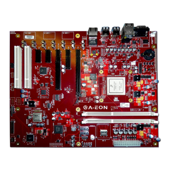
Summary of Contents for A-EON AMIGAONE X5000
- Page 1 CYRUS PLUS MOTHERBOARD TECHNICAL REFERENCE MANUAL VERSION 1.1.1 AMIGAONE X5000...
-
Page 2: Table Of Contents
Serial Terminal ............................13 DDR3 DIMMs ..............................14 Size ................................. 14 Speed ..............................14 Serial Presence Detect ..........................14 XMOS Subsystem ............................15 Block Diagram ............................16 XENA Connetors ............................. 17 16 July 2014 ©A-EON Technology Cyrus Plus Technical Reference Manual 1.1.1 2/36... - Page 3 LEDs ..............................28 10.4 PCIe and PCI Slots ..........................29 10.5 Xena Connectors ..........................33 10.6 Programming Headers ........................36 10.6.1 CPLD .............................. 36 10.6.2 MCU .............................. 36 16 July 2014 ©A-EON Technology Cyrus Plus Technical Reference Manual 1.1.1 3/36...
- Page 4 16 July 2014 ©A-EON Technology Cyrus Plus Technical Reference Manual 1.1.1 4/36...
- Page 5 Figure 5: Front Panel LED and switches ........................ 27 Figure 6: Cyrus Jumpers ............................27 Figure 7: Cyrus Plus LEDs ............................28 Figure 8: PCIe and PCI slots........................... 29 Figure 9: Programming Headers ........................... 36 16 July 2014 ©A-EON Technology Cyrus Plus Technical Reference Manual 1.1.1 5/36...
- Page 6 Table 26: Xorro Slot Signal Descriptions ....................... 35 Table 27: XTAG Connector Pinout ........................35 Table 28: CPLD JTAG Header ..........................36 Table 29: MCU Programming Header ........................36 16 July 2014 ©A-EON Technology Cyrus Plus Technical Reference Manual 1.1.1 6/36...
-
Page 7: Introduction
Real time clock Open Drain Pulled-Up Pulled-Down Read only Read write Binary-coded decimal ACPI Advanced Configuration and Power Interface Secure Digital ASCII American Standard Code for Information Interchange 16 July 2014 ©A-EON Technology Cyrus Plus Technical Reference Manual 1.1.1 7/36... -
Page 8: Architecture
(1333MT/s) and 18 SerDes channels. The Power Architecture e500mc cores adhere to most of the Power ISA v2.06 for more information on the e500mc check the Freescale website. 16 July 2014 ©A-EON Technology Cyrus Plus Technical Reference Manual 1.1.1 8/36... -
Page 9: P5020
The CPLD provides glue logic and control registers. It also provides a fast mailbox and data interface between the CPU and the XENA device. For further details on the CPLD, see section 7.1 and for the XENA see section 6.5. 16 July 2014 ©A-EON Technology Cyrus Plus Technical Reference Manual 1.1.1 9/36... -
Page 10: Boot Sd Card
BIOS in the first 1258 blocks. For more information see section 9. BIOS A micro SD card provided will hold BIOS code. The BIOS code is maintained by Hyperion. 16 July 2014 ©A-EON Technology Cyrus Plus Technical Reference Manual 1.1.1 10/36... -
Page 11: Cpu
Boot does not used hardware flow control. UART 1 is connected to the MCU to get temperature and voltage readings. For further details on the supervisor interface see section 8.1. 16 July 2014 ©A-EON Technology Cyrus Plus Technical Reference Manual 1.1.1 11/36... -
Page 12: Gpios
IRQ10 Jumper 5, JP5 GPIO, input, PU IRQ11 XMOS SPI data steering mux GPIO, output, PD Table 4: CPU External interrupts C CONTROLLER 16 July 2014 ©A-EON Technology Cyrus Plus Technical Reference Manual 1.1.1 12/36... -
Page 13: Serial Terminal
For serial communications, on a PC it is recommended to use TeraTerm. The serial port control must be configured as follows: ▪ 115200 Baud ▪ 8 bit data ▪ No Parity ▪ 1 Stop bit ▪ No Flow Control 16 July 2014 ©A-EON Technology Cyrus Plus Technical Reference Manual 1.1.1 13/36... -
Page 14: Ddr3 Dimms
SERIAL PRESENCE DETE CT The Serial Presence Detect (SPD) addresses of the 2 DIMM sockets is are as follows: Socket Address DIMM1 0x51 DIMM2 0x52 Table 6: SIMM SPD Addresses 16 July 2014 ©A-EON Technology Cyrus Plus Technical Reference Manual 1.1.1 14/36... -
Page 15: Xmos Subsystem
Xorro slot is not required, the PCI Express slot connector can be used for conventional PCI Express x1 add-in cards. This section provides essential details of Cyrus Plus’s XMOS subsystem, and should be read in conjunction with relevant XMOS documentation. 16 July 2014 ©A-EON Technology Cyrus Plus Technical Reference Manual 1.1.1 15/36... -
Page 16: Block Diagram
BLOCK DIAGRAM Figure 2 shows how Xena is connected to the main processor, the CPLD, the XTAG debug header and the Xorro slot. Figure 2: XMOS Subsystem Block Diagram 16 July 2014 ©A-EON Technology Cyrus Plus Technical Reference Manual 1.1.1 16/36... -
Page 17: Xena Connetors
If one is connected, the CPLD will float most of its pins, allowing the XTAG to take over. It will, however, still provide automatic routing of the TDI/TDO signal chain through a Xorro card, if required, so that the XTAG can control both Xena and Xorro together. 16 July 2014 ©A-EON Technology Cyrus Plus Technical Reference Manual 1.1.1 17/36... -
Page 18: Cpu Comms
XMOS to CPU mailbox 0x8000-0x8FFF Dual port RAM , 16 bits wide, 4kbytes 0x0030 XSCR1 XMOS Scratch register 0x0031 XSCR2 XMOS Scratch register Table 8: XMOS CPLD memory map 16 July 2014 ©A-EON Technology Cyrus Plus Technical Reference Manual 1.1.1 18/36... -
Page 19: Xorro Slot
Warning: When using the Haze Xorro header make sure that you have configured the Xena IOs so that it is not driving outputs onto the CPU output signals. 16 July 2014 ©A-EON Technology Cyrus Plus Technical Reference Manual 1.1.1 19/36... -
Page 20: Cpld
Table 10: CPLD Local bus memory map Notes: 1. The FAN_TACHO signal should be read multiple times to get rid of metastability. VID values are relevant to P5040 boards only. 16 July 2014 ©A-EON Technology Cyrus Plus Technical Reference Manual 1.1.1 20/36... -
Page 21: Cpld Xmos Debug Register
The format of the CPLD build time and date are stored in a 32-bit value using BCD, on for build date and one for build time. The date is store as YYYYMMDD and the time is store as 00HHMMSS. 16 July 2014 ©A-EON Technology Cyrus Plus Technical Reference Manual 1.1.1... -
Page 22: Mcu
To read the temperature readings, the 't' command is used. Returns the temperatures in the following format: $t<sign>HH...<sign>HH Where HH is the ASCII hex value of the temperature, and <sign> is either '+' or '-'. 16 July 2014 ©A-EON Technology Cyrus Plus Technical Reference Manual 1.1.1 22/36... -
Page 23: Voltages
11. Core B, 1.0V for P3041 1.1V for P5020, 1.1V-1.2V for P5040 12. DDR3 IO, 1.5V 13. Serdes, 1.8V Example for the above default values: CPU command MCU Returns $v031E031E01000100031E023201140100010A010A013201500041 16 July 2014 ©A-EON Technology Cyrus Plus Technical Reference Manual 1.1.1 23/36... -
Page 24: Cpu Fan Speed
The pinout of the Debug serial terminal is give below in Table 14. MCU Connection MCU Direction Ground MCU RX MCU TX Table 14: MCU serial pinout Notes: Pins 2-4 and 6 are unconnected. 16 July 2014 ©A-EON Technology Cyrus Plus Technical Reference Manual 1.1.1 24/36... - Page 25 To set up a serial communications on a PC, it is recommended to use TeraTerm. The serial port must be configured as follows: ▪ 38400 Baud ▪ 8 bit data ▪ No Parity ▪ 1 Stop bit ▪ No Flow Control 16 July 2014 ©A-EON Technology Cyrus Plus Technical Reference Manual 1.1.1 25/36...
-
Page 26: Boot
USB Boot=run aosusbboot bootmenu_2 Net Boot=run aosnetboot bootmenu_3 SATA 0 Boot=sata init; run aossata1boot bootmenu_4 SATA 1 Boot=sata init; run aossata1boot Table 17: U-Boot Amiga OS boot setting 16 July 2014 ©A-EON Technology Cyrus Plus Technical Reference Manual 1.1.1 26/36... -
Page 27: Connector, Jumper And Leds
Controls the state of CPU GPIO1 which is pulled up. Fitting a jumper causes the signal to be grounded. Controls VGA enable, 1 - U-Boot serial, 0 - U-Boot VGA if available. Table 18: Jumpers 16 July 2014 ©A-EON Technology Cyrus Plus Technical Reference Manual 1.1.1 27/36... -
Page 28: Leds
12V (they will directly drive any standard LED assuming it is rated for 20mA or more). P12 is pinned out as follows: 1,2 = +/anode, 3 = -/cathode. P10 and P13 are pinned out as follows: 1 = +/anode, 2 = -/cathode. Pin 1 is marked by an arrow in each case. 16 July 2014 ©A-EON Technology Cyrus Plus Technical Reference Manual 1.1.1... -
Page 29: Pcie And Pci Slots
PCIe and PCI slots is shown in Figure 8. PCI Slots PCIe Slots SLOT7 SLOT6 SLOT5 SLOT4 SLOT3 SLOT2 SLOT1 Figure 8: PCIe and PCI slots 16 July 2014 ©A-EON Technology Cyrus Plus Technical Reference Manual 1.1.1 29/36... -
Page 30: Table 20: Pcie X16 Slots Pinout
PERn4 PERn14 PETp5 PETp15 PETn5 PETn15 PERp5 PERp15 PERn5 PERn15 PRSNT2# PETp6 RSVD Table 20: PCIe x16 Slots Pinout Note: Slot 1 lanes 4-15 are always no connect. 16 July 2014 ©A-EON Technology Cyrus Plus Technical Reference Manual 1.1.1 30/36... -
Page 31: Table 21: Pcie X4 Slots Pinout
+12V +12V +12V +12V +12V SMCLK SMDAT +3.3V +3.3V TRST# +3.3V 3.3VAUX PERST# WAKE# RSVD REFCLK+ REFCLK- PETp0 PETn0 PERp0 PERn0 PRSNT2# Table 22: PCIe x1 Slots Pinout 16 July 2014 ©A-EON Technology Cyrus Plus Technical Reference Manual 1.1.1 31/36... -
Page 32: Table 23: Pci Slots Pinout
AD[06] +3.3V AD[25] AD[04] AD[05] AD[24] +3.3V AD[03] IDSEL C/BE[3]# AD[02] +3.3V AD[23] AD[00] AD[01] AD[22] AD[20] AD[21] REQ64# ACK64# AD[19] AD[18] +3.3V Table 23: PCI Slots Pinout 16 July 2014 ©A-EON Technology Cyrus Plus Technical Reference Manual 1.1.1 32/36... -
Page 33: Xena Connectors
X1D32 P4E2 P8C6 P16B6 X1D33 P4E3 P8C7 P16B7 X1D35 P1L0 X1D37 P1N0 P8D1 P16B9 X1D39 P1P0 P8D3 P16B11 Table 24: Xorro Slot Pinout - A row Ports Links 16 July 2014 ©A-EON Technology Cyrus Plus Technical Reference Manual 1.1.1 33/36... -
Page 34: Table 25: Xorro Slot Pinout - B Row
P8C1 P16B1 X1D28 P4F0 P8C2 P16B2 X1D29 P4F1 P8C3 P16B3 X1D34 P1K0 X1D36 P1M0 P8D0 P16B8 X1D38 P1I0 P8D2 P16B10 Table 25: Xorro Slot Pinout - B row 16 July 2014 ©A-EON Technology Cyrus Plus Technical Reference Manual 1.1.1 34/36... -
Page 35: Table 26: Xorro Slot Signal Descriptions
1. The XTAG# signal is wired to ground on the XTAG debugger and is used to sense its presence by Cyrus Plus (it is pulled up to 3.3V). 16 July 2014 ©A-EON Technology Cyrus Plus Technical Reference Manual 1.1.1 35/36... -
Page 36: Programming Headers
Table 28: CPLD JTAG Header 10.6.2 MCU The pinout for H3 (labelled MCU PROG) is shown in Table 28 below: Signal PDI DATA 3.3VSB PDI CLK Ground Table 29: MCU Programming Header 16 July 2014 ©A-EON Technology Cyrus Plus Technical Reference Manual 1.1.1 36/36...
Need help?
Do you have a question about the AMIGAONE X5000 and is the answer not in the manual?
Questions and answers