Olivetti d-Color MF201 Service Manual
Hide thumbs
Also See for d-Color MF201:
- Quick manual (205 pages) ,
- User manual (453 pages) ,
- Operating instructions manual (276 pages)
Table of Contents
Advertisement
Quick Links
Download this manual
See also:
Quick Manual
Advertisement
Table of Contents

Related Manuals for Olivetti d-Color MF201


Summary of Contents for Olivetti d-Color MF201
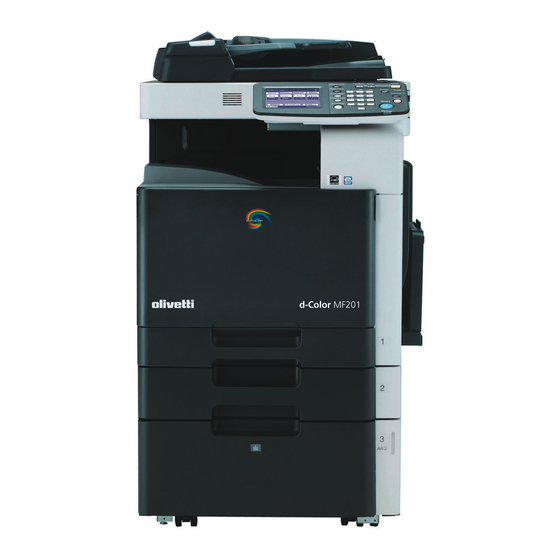
- Page 1 Color Printer d-Color MF201 SERVICE MANUAL Code Y109660-1...
- Page 2 PUBLICATION ISSUED BY: Olivetti S.p.A. 77, Via Jervis - 10015 Ivrea (TO) Italy Copyright © 2008, Olivetti All rights reserved...
-
Page 3: Revision History
Revision history After publication of this service manual, the parts and mechanism may be subject to change for improvement of their performance. Therefore, the descriptions given in this service manual may not coincide with the actual machine. When any change has been made to the descriptions in the service manual, a revised version will be issued with a revision mark added as required. -
Page 4: Table Of Contents
Field Service Ver. 1.0 Jun. 2008 CONTENTS d-Color MF201 Main body Outline System configuration....................1 Product specifications ..................... 3 Maintenance Periodical check ...................... 9 Maintenance items....................9 3.1.1 Main body ..................... 9 3.1.2 DF-612 ......................10 Maintenance parts ....................11 3.2.1... - Page 5 Field Service Ver. 1.0 Jun. 2008 Copy materials ....................30 4.3.1 Imaging unit single parts (IU)..............30 4.3.2 Toner cartridge single parts (T/C) ............... 30 4.3.3 Waste toner box..................30 4.3.4 Maintenance kit................... 30 Firmware upgrade....................31 Preparations for firmware rewriting..............31 5.1.1 Items required.....................
- Page 6 Field Service Ver. 1.0 Jun. 2008 6.3.20 ADF glass assy ................... 52 6.3.21 Tray 1 feed roller..................52 6.3.22 Tray 1 separation roller assy ............... 53 6.3.23 Fusing unit ....................54 6.3.24 PH unit ......................55 6.3.25 Main drive unit..................... 60 6.3.26 Transport drive unit ..................
- Page 7 Field Service Ver. 1.0 Jun. 2008 6.4.1 Transfer belt unit ..................107 6.4.2 PH window Y,M,C,K .................. 107 6.4.3 Tray 1 feed roller ..................108 6.4.4 Tray 1 separation roller ................108 Mount the original size detection sensor/2 (PS204) ......... 109 Adjustment/Setting How to use the adjustment section ..............
- Page 8 Field Service Ver. 1.0 Jun. 2008 8.6.4 Document Management................134 8.6.5 Printer Settings ..................134 8.6.6 Fax Settings ....................134 8.6.7 TX Settings ....................134 8.6.8 RX Settings ....................134 8.6.9 Report Settings ..................134 8.6.10 Print Lists ....................134 8.6.11 Network Settings ..................
- Page 9 Field Service Ver. 1.0 Jun. 2008 10.5.2 Exhaust Fan Stop Delay ................169 10.5.3 Serial Number................... 170 10.5.4 No Sleep ....................170 10.5.5 Foolscap Size Setting ................170 10.5.6 Install Date....................170 10.5.7 Change Fixed Zoom ................. 171 10.5.8 File Display ....................171 10.5.9 Memory Clear ...................
- Page 10 Field Service Ver. 1.0 Jun. 2008 10.8.8 IU Lot No....................263 10.8.9 Machine Configuration ................263 10.9 Test Mode ......................264 10.9.1 Procedure for test pattern output .............. 264 10.9.2 Gradation Pattern..................264 10.9.3 Halftone Pattern ..................265 10.9.4 Lattice Pattern ...................
- Page 11 Field Service Ver. 1.0 Jun. 2008 15.1.1 Skew adjustment..................275 Troubleshooting Jam display ......................277 16.1 Misfeed display ....................277 16.1.1 Misfeed display resetting procedure ............278 16.2 Sensor layout....................279 16.3 Solution ......................280 16.3.1 Initial check items ..................280 16.3.2 Solution when paper curl occurs...............
- Page 12 Field Service Ver. 1.0 Jun. 2008 17.5.6 C2254: Color PC motor’s turning at abnormal timing ....... 300 17.5.7 C225D: Color dev. unit engagement/disengagement failure..... 300 17.5.8 C2451: Release new transfer belt unit ............301 17.5.9 C2551: Abnormally low toner density detected cyan TCR sensor .... 301 17.5.10 C2553: Abnormally low toner density detected magenta TCR sensor ..
- Page 13 Field Service Ver. 1.0 Jun. 2008 17.5.43 C4153: Polygon motor rotation trouble (Y) ..........309 17.5.44 C4154: Polygon motor rotation trouble (K) ..........309 17.5.45 C4551: Laser malfunction (C)..............310 17.5.46 C4552: Laser malfunction (M) ..............310 17.5.47 C4553: Laser malfunction (Y) ..............310 17.5.48 C4554: Laser malfunction (K) ..............
- Page 14 Field Service Ver. 1.0 Jun. 2008 19.3.5 Scanner system: blurred image, blotchy image ........326 19.3.6 Scanner system: incorrect color image registration, sync shift (lines in main scan direction)................... 327 19.3.7 Scanner system: moire ................328 19.3.8 Scanner system: skewed image ............... 329 19.3.9 Scanner system: distorted image..............
- Page 15 Field Service Ver. 1.0 Jun. 2008 19.3.37 Printer 4-color: brush effect, blurred image ..........360 19.3.38 Printer 4-color: back marking..............361 19.3.39 Printer 4-color: uneven image..............362 Appendix Parts layout drawing.................... 363 20.1 Main body......................363 20.1.1 Scanner section ..................363 20.1.2 Engine section ..................
-
Page 16: Outline
Field Service Ver. 1.0 Jun. 2008 1. System configuration Outline System configuration 1/2 System front view [13] [12] [11] [10] A02FT1E007AA Main body Desk DK-504 Original cover OC-508 Paper feed cabinet PC-104 Automatic document feeder DF-612 [10] Paper feed cabinet PC-204 Working table WT-503... - Page 17 1. System configuration Field Service Ver. 1.0 Jun. 2008 2/2 System rear view A02FT1E008AA Main body Fax multi line ML-504 Stamp unit SP-503 Fax kit FK-507 Expanded memory unit EM-310 Service Manual Y109660-1...
-
Page 18: Product Specifications
Field Service Ver. 1.0 Jun. 2008 2. Product specifications Product specifications A. Type Type Desktop/console *1 scanner/printer Printing process Laser electrostatic printing system PC drum type OPC drum: KM-12 (OPC with high mold releasability) Scanning resolution 600 dpi File memory 64 MB + 512 MB (Option) Exposure lamp White rare-gas fluorescent lamp... - Page 19 2. Product specifications Field Service Ver. 1.0 Jun. 2008 B. Functions Types of original Sheets, books, and three-dimensional objects Max. original size Book scanner A3 or 11 x 17 Max. original weight Book scanner Max. 2 kg Multiple copies 1 to 999 Warm-up time When the sub power switch is turned ON at any timing while the main power (at ambient tempera-...
- Page 20 Field Service Ver. 1.0 Jun. 2008 2. Product specifications C. Paper Paper source (maximum tray capacity) Type Tray 2 Multiple bypass Tray 1 (Option) (Option) Plain paper 250 sheets 500 sheets 100 sheets (60 to 90 g/m / 16 to 24 lb) Thick paper 1 (91 to 150 g/m 24.2 to 40 lb)
- Page 21 2. Product specifications Field Service Ver. 1.0 Jun. 2008 D. Maintenance Color print 500 prints No. of pages printed per month (average) Monochrome print 2,300 prints Color print 2 pages/job Standard copy mode Monochrome print 2 pages/job Color print C, M, Y, K : 5% Standard original density Monochrome print...
- Page 22 Field Service Ver. 1.0 Jun. 2008 2. Product specifications G. Print functions Type Built-in type controller Ethernet (10Base-T or 100Base-TX), Host interface USB 2.0/1.1 Print speed 20 prints/min (color/monochrome, A4, 1-sided) Resolution 600 dpi x 600 dpi PCL5e/c emulation Printer language PCL XL Ver.
- Page 23 2. Product specifications Field Service Ver. 1.0 Jun. 2008 Blank Page Service Manual Y109660-1...
-
Page 24: Maintenance
Field Service Ver. 1.0 Jun. 2008 3. Periodical check Maintenance Periodical check Maintenance items NOTE • Cleaning/replacement cycle for each maintenance item of main body/options can be evaluated with each life counter value of [Service mode] [Counter] [Life]. 3.1.1 Main body A. -
Page 25: Df-612
3. Periodical check Field Service Ver. 1.0 Jun. 2008 D. Periodical parts replacement/cleaning 2 (per 120,000-print/-sheet scan) Lubri- Descrip- Class Parts to be replaced Check Clean Replace cation tions Paper feed and image ● conditions Overall ● ● Appearance ● Exposure lamp Scanner ●... -
Page 26: Maintenance Parts
Field Service Ver. 1.0 Jun. 2008 3. Periodical check Maintenance parts • To ensure that the machine produces good copies and to extend its service life, it is rec- ommended that the maintenance jobs described in this schedule be carried out as instructed. -
Page 27: Cleaning Parts
3. Periodical check Field Service Ver. 1.0 Jun. 2008 3.2.2 Cleaning parts Descrip No. Classification Parts name Actual cleaning cycle *1 Ref.Page tions Original glass assy 30,000 P.27 Scanner Exposure lamp 120,000 P.28 section Each mirror and lens 120,000 P.28 Conveyance Timing roller Upon each call (60,000) -
Page 28: Concept Of Parts Life
Field Service Ver. 1.0 Jun. 2008 3. Periodical check Concept of parts life 3.3.1 Life value of consumables and parts • The life counter value of each materials and parts is available from [Service Mode] [Counter] [Life]. • Life specification value means an actual life terminated when prints are made under the conditions as defined in the next section, “Conditions for life specifications values.”... -
Page 29: Conditions For Life Specifications Values
3. Periodical check Field Service Ver. 1.0 Jun. 2008 *6: The count condition is different according to the paper length of the sub scanning direc- tion. Paper length of Count value sub scanning direction Less than 216 mm 1 count 216 mm to 432 mm 2 counts 432 mm or more... -
Page 30: Maintenance Procedure (Periodical Check Parts)
Field Service Ver. 1.0 Jun. 2008 3. Periodical check Maintenance procedure (periodical check parts) NOTE • The alcohol described in the cleaning procedure of maintenance represents the isopropyl alcohol. 3.4.1 Cleaning of the timing roller A. Periodically cleaning parts/cycle • Timing roller: Every 60,000 prints (upon each call) B. -
Page 31: Replacing The Waste Toner Box
3. Periodical check Field Service Ver. 1.0 Jun. 2008 3.4.3 Replacing the waste toner box A. Periodically replacing parts/cycle • Waste toner box: Every 50,000 prints B. Removal procedure 1. Open the front door. 2. Raise the waste toner box [1] and remove it. -
Page 32: Replacing The Transfer Roller Unit
Field Service Ver. 1.0 Jun. 2008 3. Periodical check 3.4.4 Replacing the transfer roller unit A. Periodically replacing parts/cycle • Transfer roller unit: Every 120,000 prints B. Removal procedure 1. Open the right door. 2. Unlock the lock levers [1] of the transfer roller unit (at two places). -
Page 33: Replacing The Imaging Unit
3. Periodical check Field Service Ver. 1.0 Jun. 2008 3.4.5 Replacing the imaging unit A. Periodically replacing parts/cycle • Imaging unit Y,M,C : Every 45,000 prints • Imaging unit K : Every 60,000 prints NOTE • Although the procedure shown below is for the replacement of the imaging unit K, use the same procedure to replace other imaging units Y,M,C. - Page 34 Field Service Ver. 1.0 Jun. 2008 3. Periodical check C. Reinstall procedure 1. Remove the imaging unit [1] from its packaging. A02EF2C508DA 2. Peel off the tapes, and then remove the packing materials [1]. A02EF2C509DA 3. Remove the imaging unit [2] from the black protective bag [1].
- Page 35 3. Periodical check Field Service Ver. 1.0 Jun. 2008 4. Tilt the imaging unit [1] to the left and shake it a little left to right twice. Then, tilt the imaging unit to the right and shake it a little right to left twice. A02EF2C511DA 5.
- Page 36 Field Service Ver. 1.0 Jun. 2008 3. Periodical check 7. Align the ▲ mark on the imaging unit with the ▼ mark on the main body. Install the imaging unit [1] into the main body. A02EF2C514DA 8. To remove the protective sheet [1] which guards against PC drum dam- age, slowly pull its tab.
-
Page 37: Replacing The Ozone Filter
3. Periodical check Field Service Ver. 1.0 Jun. 2008 3.4.6 Replacing the ozone filter A. Periodically replacing parts/cycle • Ozone filter: Every 120,000 prints B. Procedure 1. Grip the handle on the ozone filter [1] and slide it out of the main body. A02FF2C005DA 3.4.7 Replacing the toner cartridge... - Page 38 Field Service Ver. 1.0 Jun. 2008 3. Periodical check C. Reinstall procedure 1. Remove the new toner cartridge [1] from its packaging, and then shake the cartridge up and down 5 to 10 times. A02EF2C518DA 2. Align the toner cartridge [1] with the slots in the machine, and then insert the cartridge until the locking tab locks into place.
-
Page 39: Replacing The Transfer Belt Unit
3. Periodical check Field Service Ver. 1.0 Jun. 2008 3.4.8 Replacing the transfer belt unit A. Periodically replacing parts/cycle • Transfer belt unit: Every 120,000 prints NOTE • Before replacement operations of the transfer belt unit, make sure to turn OFF the main power switch and the sub power switch. - Page 40 Field Service Ver. 1.0 Jun. 2008 3. Periodical check C. Reinstall procedure 1. Insert the transfer belt unit [1]. NOTE • Insert the transfer belt unit with care not to allow its docking gear to be damaged by hitting it against the rail or associated part.
-
Page 41: Cleaning Of The Image Transfer Entrance Guide
3. Periodical check Field Service Ver. 1.0 Jun. 2008 3.4.9 Cleaning of the image transfer entrance guide A. Periodically cleaning parts/cycle • Image transfer entrance guide: When the transfer belt unit is replaced (every 120,000 print) B. Procedure 1. Remove the transfer belt unit. See P.24 2. -
Page 42: Cleaning Of The Original Glass Assy
Field Service Ver. 1.0 Jun. 2008 3. Periodical check 3.4.11 Cleaning of the original glass assy A. Periodically cleaning parts/cycle • original glass assy: Every 30,000 sheets scan B. Procedure 1. Open the original cover or the ADF. 2. Clean the surface of the original glass [1] using a cleaning pad. -
Page 43: Cleaning Of The Exposure Lamp
3. Periodical check Field Service Ver. 1.0 Jun. 2008 3.4.12 Cleaning of the exposure lamp A. Periodically cleaning parts/cycle • Exposure lamp: Every 120,000 sheets scan B. Procedure 1. Remove the original glass assy. See P.51 2. Wipe the exposure lamp [1] clean of dirt using a cleaning pad. -
Page 44: Service Tool
Field Service Ver. 1.0 Jun. 2008 4. Service tool Service tool Service material list Name Shape Material No. Remarks Cleaning pad _________1 10pcs/1pack A02EF2C526DA Isopropyl alcohol A00KF2C506DA CE tool list Tool name Shape Quantity Parts No. Remarks PH window cleaning jig AVGR05391U 4038F2C557DA PH window cleaning jig... -
Page 45: Copy Materials
4. Service tool Field Service Ver. 1.0 Jun. 2008 Copy materials 4.3.1 Imaging unit single parts (IU) Parts name Replacing period Imaging unit K 60,000 prints Imaging unit Y 45,000 prints Imaging unit M 45,000 prints Imaging unit C 45,000 prints See P.13 4.3.2 Toner cartridge single parts (T/C) -
Page 46: Firmware Upgrade
Field Service Ver. 1.0 Jun. 2008 5. Firmware upgrade Firmware upgrade Preparations for firmware rewriting 5.1.1 Items required • Drive which enables writing/reading of compact flash • Compact flash (service tool) 5.1.2 Writing data to compact flash 1. Prepare firmware data. 2. -
Page 47: Firmware Rewriting Procedures
5. Firmware upgrade Field Service Ver. 1.0 Jun. 2008 Firmware rewriting procedures NOTE • NEVER remove or insert the compact flash card with the machine power turned • Confirm the current version before upgrading the firmware. • Before upgrading the firmware, confirm that no jobs remain within the machine. 5.2.1 Controller 1. -
Page 48: Engine/Job Separator
Field Service Ver. 1.0 Jun. 2008 5. Firmware upgrade 7. Remove the compact flash card [1] from the slot. A02FF2C526DA 8. Reinstall the cover of the slot. 9. Turn ON the main power switch and the sub power switch. 10. Select [Admin.] [Firmware Version]. - Page 49 5. Firmware upgrade Field Service Ver. 1.0 Jun. 2008 3. Insert the compact flash [1], to which the engine and job separator firm- ware data is copied, into the slot. A02FF2C526DA 4. Turn ON the main power switch and the sub power switch. 5.
- Page 50 Field Service Ver. 1.0 Jun. 2008 5. Firmware upgrade 8. Check the message, then select [Yes]. A02FF2E529DA 9. The screen on the left will appear as soon as downloading starts. NOTE • While this screen is being dis- played, which indicates that the firmware is being rewritten, never turn OFF the main power switch or sub power switch, unplug the...
- Page 51 5. Firmware upgrade Field Service Ver. 1.0 Jun. 2008 13. Remove the compact flash card [1] from the slot. A02FF2C526DA 14. Reinstall the cover of the slot. 15. Turn ON the main power switch. 16. Select [Admin.] [Firmware Version]. 17. Check that the firmware version has been updated. Service Manual Y109660-1...
-
Page 52: Other
Field Service Ver. 1.0 Jun. 2008 6. Other Other Disassembly/adjustment prohibited items A. Paint-locked screws NOTE • To prevent loose screws, a screw lock in blue or green series color is applied to the screws. • The screw lock is applied to the screws that may get loose due to the vibrations and loads created by the use of machine or due to the vibrations created during transportation. -
Page 53: Disassembly/Assembly/Cleaning List (Other Parts)
6. Other Field Service Ver. 1.0 Jun. 2008 Disassembly/assembly/cleaning list (other parts) 6.2.1 Disassembly/assembly parts list Section Part name Ref. page Front door P.40 Upper front cover P.41 Right front cover P.41 Left cover P.42 Left shield cover P.42 Rear left cover P.43 Exit cover P.43... -
Page 54: Cleaning Parts List
Field Service Ver. 1.0 Jun. 2008 6. Other Section Part name Ref. page ADCU board (ADCUB) P.86 MFBU board (MFBUB) P.87 PWBs BCRU board (BCRUB) P.89 Inverter board (INVB) P.90 Transport motor (M1) P.91 Color PC motor (M3) P.92 Fusing motor (M2) P.92 Motors Fusing pressure roller retraction motor (M12) -
Page 55: Disassembly/Assembly Procedure
6. Other Field Service Ver. 1.0 Jun. 2008 Disassembly/assembly procedure 6.3.1 Front door 1. Open the front door. 2. Remove two screws [1] and the sup- pression plate [2]. A02FF2C011DA 3. Remove the PH window cleaning jig [1]. A02FF2C012DA 4. Slide the pins [1] in the direction of the arrow and remove it. -
Page 56: Upper Front Cover
Field Service Ver. 1.0 Jun. 2008 6. Other 6.3.2 Upper front cover 1. Open the front door. 2. Open the right door. 3. Remove two screws [1], and remove the upper front cover [2]. A02FF2C014DA 6.3.3 Right front cover 1. Remove the upper front cover. See P.41 2. -
Page 57: Left Cover
6. Other Field Service Ver. 1.0 Jun. 2008 5. Remove four screws [1], and remove the right front cover [2]. A02FF2C016DA 6.3.4 Left cover 1. Open the front door. 2. Remove three screws [1], and remove the left cover [2]. A02FF2C017DA 6.3.5 Left shield cover... -
Page 58: Rear Left Cover
Field Service Ver. 1.0 Jun. 2008 6. Other 4. Remove twelve screws [1], and remove the left shield cover [2]. A02FF2C019DA 6.3.6 Rear left cover 1. Remove the ozone filter. See P.22 2. Remove the left cover. See P.42 3. Remove four screws [1], and remove the rear left cover [2]. -
Page 59: Ir Rear Cover
6. Other Field Service Ver. 1.0 Jun. 2008 6.3.8 IR rear cover 1. Remove six screws [1], and remove the IR rear cover [2]. A02FF2C022DA 6.3.9 Paper exit rear cover 1. Remove the rear left cover. See P.43 2. Remove the IR rear cover. See P.44 3. -
Page 60: Rear Cover
Field Service Ver. 1.0 Jun. 2008 6. Other 6.3.10 Rear cover 1. Remove the IR rear cover. See P.44 2. Remove seven screws [1], and remove the rear cover [2]. A02FF2C023DA 6.3.11 Rear right cover 1. Open the right door. 2. -
Page 61: Control Panel Assy
6. Other Field Service Ver. 1.0 Jun. 2008 6.3.12 Control panel assy 1. Lower the control panel down to the bottommost position. 2. Remove two screws [1]. A02FF2C025DA 3. Raise the control panel to the topmost position. 4. Remove four screws [1], and remove the control panel lower cover [2]. -
Page 62: Exit Tray
Field Service Ver. 1.0 Jun. 2008 6. Other 6.3.13 Exit tray 1. Open the front door. 2. Remove the left cover. See P.42 3. Remove three screws [1], and remove the exit tray [2]. A02FF2C028DA 6.3.14 Tray 1 1. Slide out the tray 1. 2. -
Page 63: Front Cover
6. Other Field Service Ver. 1.0 Jun. 2008 4. Pushing the slide locks [1] on both ends, remove the tray 1 [2]. A02FF2C030DA 6.3.15 Front cover 1. Slide out the tray 1. 2. Remove the front door. See P.40 3. Remove the left cover. See P.42 4. - Page 64 Field Service Ver. 1.0 Jun. 2008 6. Other 8. Disconnect three connectors [1], and remove the harness from the wire saddle [2]. A02FF2C036DA 9. Remove the right front cover. See P.41 10. Disconnect two connectors [1]. A02EF2C071DA 11. Remove five screws [1]. A02EF2C072DA Y109660-1 Sevice Manual...
-
Page 65: Ir Upper Front Cover
6. Other Field Service Ver. 1.0 Jun. 2008 12. Unhook six tabs [1], and disconnect the connector [2] from the front cover. 13. Remove the front cover [3]. A02EF2C073DA 6.3.16 IR upper front cover 1. Remove two screws [1], and remove the IR upper front cover [2]. -
Page 66: Ir Right Cover
Field Service Ver. 1.0 Jun. 2008 6. Other 6.3.18 IR right cover 1. Remove the IR rear cover. See P.44 2. Remove two screws [1], and remove the IR right cover [2]. A02FF2C105DA 6.3.19 Original glass assy 1. Remove the IR rear cover. See P.44 2. -
Page 67: Adf Glass Assy
6. Other Field Service Ver. 1.0 Jun. 2008 6.3.20 ADF glass assy 1. Remove the IR rear cover. See P.44 2. Remove the IR left cover. See P.50 3. Remove two screws [1], and remove the ADF glass assy [2]. A02FF2C107DA 6.3.21 Tray 1 feed roller... -
Page 68: Tray 1 Separation Roller Assy
Field Service Ver. 1.0 Jun. 2008 6. Other 5. Remove two C-clips [1] and the col- lar [2], and remove the tray 1 feed roller [3]. 9J06F2C501DA 6.3.22 Tray 1 separation roller assy 1. Slide out the tray 1. 2. Remove two screws [1], and remove the tray 1 separation roller fixing plate assy [2]. -
Page 69: Fusing Unit
6. Other Field Service Ver. 1.0 Jun. 2008 4. Snap off the E-ring [1] and the tray 1 separation roller assy [2]. A02FF2C034DA 6.3.23 Fusing unit CAUTION • The temperature gets high in the vicinity of the fusing unit. You may get burned when you come into contact with the area. -
Page 70: Ph Unit
Field Service Ver. 1.0 Jun. 2008 6. Other 6. Remove two screws [1], and remove the fusing unit [2]. NOTE • When removing the fusing unit, hold the parts shown on the picture on the left so that it would not fall. A02FF2C037DA 6.3.24 PH unit... - Page 71 6. Other Field Service Ver. 1.0 Jun. 2008 4. Disconnect four flat cables [1] and four connectors [2] of the PH unit. A02EF2C075DA 5. Unhook the tab [1], and remove the gear [2] of the PH unit. NOTE • This step is not needed when removing PH unit (Black) that does not have a gear.
- Page 72 Field Service Ver. 1.0 Jun. 2008 6. Other 7. Remove the PH unit. Move the front side of the PH unit to left a little, and remove the boss [1] from the locating hole [2]. Lift up the front side of the PH unit a little.
- Page 73 6. Other Field Service Ver. 1.0 Jun. 2008 B. Reinstall procedure 1. Fit the back of the PH unit [1] into the plate spring [2] of installation plate. 4037F2C113DB 2. Push the PH unit [1] along the right side line of PH unit installation plate all the way and fit it into the plate spring [2].
- Page 74 Field Service Ver. 1.0 Jun. 2008 6. Other 4. Reinstall the stopper [1]. NOTE • When reinstalling the stopper, use care so that both ends of the stop- per will not open but stay parallel as shown on the left. Keep using the stopper after once stretched out may cause uneven pitch or other image troubles.
-
Page 75: Main Drive Unit
6. Other Field Service Ver. 1.0 Jun. 2008 8. Install the imaging unit guide rails [1]. NOTE • Make sure that the two claws [2] at rear end of the rail are fit in the locating hole on the main unit. A02EF2C081DA 9. - Page 76 Field Service Ver. 1.0 Jun. 2008 6. Other 7. Disconnect the connector [1], and remove the harness from the wire saddle [2] and the harness guide [3]. A02FF2C039DA 8. Remove two screws [1], and remove the harness guide [2]. A02FF2C040DA 9.
- Page 77 6. Other Field Service Ver. 1.0 Jun. 2008 10. Remove two screws [1], and remove the harness guide [2]. A02FF2C042DA 11. Remove the left shield cover. See P.42 12. Disconnect the connector [1]. A02FF2C043DA 13. Disconnect the connector [1], and remove the harness from four wire saddles [2] and the harness guide [3].
-
Page 78: Transport Drive Unit
Field Service Ver. 1.0 Jun. 2008 6. Other 14. Remove eight screws [1], and slide out the main drive unit [2]. A02FF2C045DA 15. Remove the E-ring [1], and remove the gear [2]. NOTE • There is a pin, which fixes the gear to the shaft, installed inside the gear. - Page 79 6. Other Field Service Ver. 1.0 Jun. 2008 4. Close the right door. 5. Remove four screws [1], and remove the reinforcement plates [2] of the right door. A02FF2C048DA 6. Remove the shoulder screw [1], the spring [2] and the collar [3]. A02FF2C049DA 7.
- Page 80 Field Service Ver. 1.0 Jun. 2008 6. Other 8. Remove the wire saddle [1]. 9. Remove the harness from five wire saddles [2] and two edge covers [3]. A02FF2C051DA 10. Remove two screws [1], and remove the cover [2]. A02FF2C052DA 11.
- Page 81 6. Other Field Service Ver. 1.0 Jun. 2008 12. Remove each six tabs [1] and two hooks [2]. 13. Remove two wire guides [3]. [1] [2] [1] [2] A02FF2C054DA 14. Remove the wire guide [1] and eight screws [3], and disconnect the con- nector [2].
-
Page 82: Fusing Drive Unit
Field Service Ver. 1.0 Jun. 2008 6. Other 6.3.27 Fusing drive unit 1. Remove the transfer belt unit. See P.24 2. Remove the fusing unit. See P.54 3. Remove the fusing motor. See P.92 4. Disconnect three connectors [1]. A02FF2C056DA 5. - Page 83 6. Other Field Service Ver. 1.0 Jun. 2008 9. Remove two screws [1], and remove the fusing rear guide [2]. A02FF2C060DA 10. Remove the spring [1] from the pro- trusion [2]. A02FF2C061DA 11. Remove six screws [1] of the fusing drive unit.
-
Page 84: Hopper Drive Unit (C/K, Y/M)
Field Service Ver. 1.0 Jun. 2008 6. Other 12. Pull the fusing drive unit [1] to the front and remove it. A02FF2C062DA 6.3.28 Hopper drive unit (C/K, Y/M) A. Hopper drive unit (C/K) 1. Remove the main drive unit. See P.60 2. -
Page 85: Right Door Assy
6. Other Field Service Ver. 1.0 Jun. 2008 6.3.29 Right door assy 1. Remove the rear handle assy. • See removal procedures 1 through 11 for the transport drive unit. (Do not, however, remove the main drive unit.) See P.63 2. -
Page 86: Scanner Chassis
Field Service Ver. 1.0 Jun. 2008 6. Other 6.3.30 Scanner chassis 1. Remove the IR rear cover. See P.44 2. Remove the IR left cover. See P.50 3. Remove the IR right cover. See P.51 4. Remove seven screws [1], and remove the MFBU shield cover [2]. - Page 87 6. Other Field Service Ver. 1.0 Jun. 2008 7. Remove three screws [1]. A02FF2C110DA 8. Remove the IR upper front cover. See P.50 9. Remove three screws [1], and remove the IR front cover [2]. A02FF2C111DA 10. Remove two screws [1], and remove the control panel upper cover [2].
- Page 88 Field Service Ver. 1.0 Jun. 2008 6. Other 11. Remove four screws [1]. A02FF2C113DA 12. Disconnect the connector [1], and remove the control panel assy [2]. A02FF2C114DA 13. Remove eight screws [1], and remove the scanner chassis [2]. A02FF2C115DA Y109660-1 Sevice Manual...
-
Page 89: Exposure Unit
6. Other Field Service Ver. 1.0 Jun. 2008 NOTE • When reinstalling the scanner chassis on the engine frame, tighten screws in the order shown below. 1. Right side (4 screws) 2. Rear side (2 screws) 3. Left side (2 screws) A02FF2C515DA 6.3.31 Exposure unit... - Page 90 Field Service Ver. 1.0 Jun. 2008 6. Other 4. Disconnect the flat cable [1]. A02FF2C122DA 5. Move the exposure unit near the center of the scanner chassis. 6. Confirm the fixing position [1] of the wire bracket at the front of the expo- sure unit.
- Page 91 6. Other Field Service Ver. 1.0 Jun. 2008 8. Move the exposure unit rightward, and remove the wire bracket from the exposure unit. 9. Rotate the exposure unit center clockwise toward the center, and remove from the scanner chassis. A02FF2C514DA NOTE •...
-
Page 92: Flat Cable Of The Exposure Unit
Field Service Ver. 1.0 Jun. 2008 6. Other 6.3.32 Flat cable of the exposure unit A. Removal procedure 1. Remove the exposure unit. See P.74 2. Remove the screw [1], and remove the cable guide [2]. A02FF2C133DA 3. Disconnect the flat cable [1]. A02FF2C537DA B. - Page 93 6. Other Field Service Ver. 1.0 Jun. 2008 2. Connect the flat cable [1] to the exposure unit. (Refer to the following illustration for the cable routing.) Take care in direction of terminal Align the marking with the edge surface of the flat cable guide, and fix the position.
-
Page 94: Ph Relay Board (Reybph)
Field Service Ver. 1.0 Jun. 2008 6. Other 6.3.33 PH relay board (REYBPH) 1. Remove the front cover. See P.48 2. Remove the transfer belt unit. See P.24 3. Remove the harness from the wire saddle [1]. 4. Remove five screws [2], and remove the front handle assy [3]. - Page 95 6. Other Field Service Ver. 1.0 Jun. 2008 7. Remove all the connectors and the flat cables on the PH relay board. A02EF2C130DA 8. Remove the stopper [1] of the PH unit. NOTE • When removing the stopper, use care so that both ends of the stop- per will not open but stay parallel as shown on the left.
-
Page 96: Dc Power Supply (Dcpu)
Field Service Ver. 1.0 Jun. 2008 6. Other 6.3.34 DC power supply (DCPU) CAUTION • Remove the DC power supply after six minutes or more have passed since the power plug was disconnected. 1. Remove the left shield cover. See P.42 2. -
Page 97: Printer Control Board (Prcb)
6. Other Field Service Ver. 1.0 Jun. 2008 5. Remove all the connectors on the DC power supply [1]. A02FF2C070DA 6. Remove nine screws [1], and remove the DC power supply [2]. A02FF2C071DA 6.3.35 Printer control board (PRCB) 1. Remove the left shield cover. See P.42 2. -
Page 98: Service Eeprom Board (Sverb)
Field Service Ver. 1.0 Jun. 2008 6. Other 3. Remove six screws [1], and remove the printer control board [2]. A02FF2C073DA NOTE • When the printer control board is to be replaced, rewriting the firmware to the lat- est one. 6.3.36 Service EEPROM board (SVERB) 1. - Page 99 6. Other Field Service Ver. 1.0 Jun. 2008 4. Enter the Service mode. Make individual adjustments shown in the following table in the order listed, using the machine maintenance list and the adjustment lists that were output at the time of main body installation and maintenance. NOTE •...
-
Page 100: High Voltage Unit (Hv)
Field Service Ver. 1.0 Jun. 2008 6. Other 6.3.37 High voltage unit (HV) 1. Remove the rear cover. See P.45 2. Disconnect seven connectors [1]. A02FF2C075DA 3. Remove five screws [1] and the tab [2], and remove the high voltage unit [3]. -
Page 101: Adcu Board (Adcub)
6. Other Field Service Ver. 1.0 Jun. 2008 4. Disconnect the connector [1]. 5. Remove two screws [2], and remove the tray 1 FD paper size detect board assy [3]. A02FF2C078DA 6. Remove the lever [1], and remove the tray 1 FD paper size detect board [2]. -
Page 102: Mfbu Board (Mfbub)
Field Service Ver. 1.0 Jun. 2008 6. Other 3. Remove the screw [1], and remove the ADCU board [2]. A02FF2C509DA 6.3.40 MFBU board (MFBUB) 1. Remove the IR rear cover. See P.44 2. Remove seven screws [1], and remove the MFBU shield cover [2]. A02FF2C508DA 3. - Page 103 6. Other Field Service Ver. 1.0 Jun. 2008 5. Remove five screws [1], and remove the MFBU board assy [2]. A02FF2C511DA 6. Remove six screws [1], and remove the MFBU board [2] from the MFBU bracket [3]. A02FF2C521DA 7. Remove the MEMU/1 [1], MEMU/2 [2] and RAMU board [3] on the MFBU board.
-
Page 104: Bcru Board (Bcrub)
Field Service Ver. 1.0 Jun. 2008 6. Other 6.3.41 BCRU board (BCRUB) 1. Remove the original glass assy. See P.51 2. Remove eight screws [1], and remove the BCRU shield cover [2]. A02FF2C101DA 3. Disconnect all connectors and flat cables on the BCRU board [1]. A02FF2C121DA 4. -
Page 105: Inverter Board (Invb)
6. Other Field Service Ver. 1.0 Jun. 2008 6.3.42 Inverter board (INVB) CAUTION • Always turn off the main power switch and disconnect the power code from an AC outlet when you remove the inverter board or exposure lamp. • High voltage will be applied to inverter board while scanning a document. Never touch it while scanning to avoid electrical shocks. -
Page 106: Transport Motor (M1)
Field Service Ver. 1.0 Jun. 2008 6. Other 6. Remove two screws [1], and remove the inverter board [2]. A02FF2C126DA 7. To reinstall, reverse the order of removal. NOTE • Take note of the housing method of the two cables [1] of the inverter board. -
Page 107: Color Pc Motor (M3)
6. Other Field Service Ver. 1.0 Jun. 2008 6.3.44 Color PC motor (M3) 1. Remove the rear cover. See P.45 2. Remove four screws [1], disconnect the connector [2], and remove the color PC motor [3]. A02FF2C080DA 6.3.45 Fusing motor (M2) 1. -
Page 108: Fusing Pressure Roller Retraction Motor (M12)
Field Service Ver. 1.0 Jun. 2008 6. Other 6.3.46 Fusing pressure roller retraction motor (M12) 1. Remove the paper exit rear cover. See P.44 2. Remove the rear cover. See P.45 3. Disconnect two connectors [1]. 4. Remove three screws [2], and remove the fusing pressure roller retraction motor assy [3]. -
Page 109: Toner Supply Motor/Ym (M6)
6. Other Field Service Ver. 1.0 Jun. 2008 6.3.48 Toner supply motor/YM (M6) 1. Remove the rear cover. See P.45 2. Disconnect the connector [2], remove two screws [1], and remove the toner supply motor/YM [3]. A02FF2C084DA 6.3.49 Scanner motor (M201) 1. -
Page 110: Transfer Belt Pressure Retraction Clutch (Cl3)
Field Service Ver. 1.0 Jun. 2008 6. Other 6. Remove the belt [1] hanging on the motor. A02FF2C118DA 7. Remove two screws [1], and remove the scanner motor [2]. A02FF2C119DA 6.3.50 Transfer belt pressure retraction clutch (CL3) 1. Remove the fusing drive unit. See P.67 2. -
Page 111: Developing Clutch/K (Cl4)
6. Other Field Service Ver. 1.0 Jun. 2008 3. Remove the transfer belt pressure retraction clutch [1]. A02EF2C196DA 6.3.51 Developing clutch/K (CL4) 1. Remove the high voltage unit. See P.85 2. Remove two screws [1], and remove the rear handle cover [2]. A02FF2C086DA 3. -
Page 112: Tim. Roller Clutch (Cl1)
Field Service Ver. 1.0 Jun. 2008 6. Other 4. Disconnect the connector [1], and remove the developing clutch/K [2]. A02FF2C088DA 6.3.52 Tim. roller clutch (CL1) 1. Remove the vertical transport unit. See the steps 1 to 7 of IDC registration sensor removing procedure. See P.97 2. - Page 113 6. Other Field Service Ver. 1.0 Jun. 2008 3. Remove the screw [1], and remove the plate spring [2]. A02FF2C090DA 4. Remove the shoulder screw [1] and the screw [2]. 5. Remove the vertical transport unit [3] as shown in the left illustration. NOTE •...
- Page 114 Field Service Ver. 1.0 Jun. 2008 6. Other 7. Remove three screws [1], and remove the metal plate [2]. NOTE • Both end screws has a spacer. Remove the screws, being careful not to drop the spacers. A02FF2C093DA 8. Disconnect the connector [1], remove two screws [2], and remove the IDC registration sensor/MK.
-
Page 115: Exposure Lamp (Fl201)
6. Other Field Service Ver. 1.0 Jun. 2008 6.3.54 Exposure lamp (FL201) CAUTION • Always turn off the main power switch and disconnect the power code from an AC outlet when you remove the inverter board or exposure lamp. • High voltage will be applied to inverter board while scanning a document. Never touch it while scanning to avoid electrical shocks. - Page 116 Field Service Ver. 1.0 Jun. 2008 6. Other 6. Remove the screw [1], and remove the exposure lamp [2]. A02FF2C128DA 7. To reinstall, reverse the order of Blue White removal. NOTE • Take care so as not to mistake the blue and white routing of the lamp cables.
-
Page 117: Scanner Drive Wires
6. Other Field Service Ver. 1.0 Jun. 2008 6.3.55 Scanner drive wires A. Removal procedure 1. Remove the original glass assy. See P.51 2. Remove the ADF glass assy. See P.52 3. Remove the IR rear cover. See P.44 4. Remove the IR left cover. See P.50 5. - Page 118 Field Service Ver. 1.0 Jun. 2008 6. Other B. Reinstall procedure • Remove the pulleys and a pulley shaft before winding the scanner drive wires. 1. Remove the screw [1], and remove the pulley [2] and the spacer [3]. A02FF2C130DA 2.
- Page 119 6. Other Field Service Ver. 1.0 Jun. 2008 4. Insert the shorter side (A) of the scanner drive wire from the opposite of the pulley screw. 5. Then, fit the mid clamp [1] to the groove. 6. Wind a wire five turns from the outer rim of the pulley.
- Page 120 Field Service Ver. 1.0 Jun. 2008 6. Other 7. Insert the pulleys [1] around which the scanner drive wire was wound to the pulley shaft [2], and fix them with one screw each. NOTE • Place the pulley marked (F) on the machine front and the pulley marked (R) on the machine rear.
- Page 121 6. Other Field Service Ver. 1.0 Jun. 2008 9. Route wires as shown below. A02FF2C519DA 10. Reinstall the exposure unit. NOTE • When fixing the wire bracket at the exposure unit front, align with the memory position when removing. 11. After mounting, while taking copy images, adjust the wire bracket fixing position at the exposure unit front so as to prevent tilting.
-
Page 122: Cleaning Procedure
Field Service Ver. 1.0 Jun. 2008 6. Other Cleaning procedure NOTE • The alcohol described in the cleaning procedure represents the ethanol isopropyl alcohol. 6.4.1 Transfer belt unit 1. Remove the transfer belt unit. See P.24 2. Using a cleaning pad, wipe the trans- fer belt [1]. -
Page 123: Tray 1 Feed Roller
6. Other Field Service Ver. 1.0 Jun. 2008 6.4.3 Tray 1 feed roller 1. Slide out the tray 1. 2. Using a cleaning pad dampened with alcohol, wipe the tray 1 feed roller [1] clean of dirt. A02FF2C095DA 6.4.4 Tray 1 separation roller 1. -
Page 124: Mount The Original Size Detection Sensor/2 (Ps204)
Field Service Ver. 1.0 Jun. 2008 6. Other Mount the original size detection sensor/2 (PS204) 1. Remove the original glass assy. See P.51 2. Remove eight screws [1], and remove the BCRU board protective shield [2]. A02FF2C101DA 3. Using the screw [1], mount the origi- nal size detection sensor/2 (PS204) [2] and fix it. - Page 125 6. Other Field Service Ver. 1.0 Jun. 2008 6. Call the service mode to the screen, and set “Bit 3 of Mode 423” of the soft switch to “0”. 7. Select [Service Mode] [State Confirmation] [Sensor Check (Scan)] [Scanner], and check the state of the original size detection sensor/2 (Original Size Detection Opt.).
-
Page 126: Adjustment/Setting
Field Service Ver. 1.0 Jun. 2008 7. How to use the adjustment section Adjustment/Setting How to use the adjustment section • “Adjustment/Setting” contains detailed information on the adjustment items and proce- dures for this machine. • Throughout this “Adjustment/Setting,” the default settings are indicated by “ ”. Advance checks •... -
Page 127: Utility Mode
8. Utility Mode Field Service Ver. 1.0 Jun. 2008 Utility Mode Utility Mode function tree * The function tree is shown to comply with the format displayed on the screen. NOTE • Keys displayed on screens are different depending on the setting. Utility Ref. - Page 128 Field Service Ver. 1.0 Jun. 2008 8. Utility Mode Utility Ref. page User Confirmation Beep P.124 Management Alarm Volume P.124 Line Monitor Sound P.124 Job Complete Beep P.124 Panel Cleaning P.124 Dehumidify P.124 POP3 RX P.125 Memory RX ON/OFF P.125 One-Touch/ One-Touch P.125...
- Page 129 8. Utility Mode Field Service Ver. 1.0 Jun. 2008 Utility Ref. page Admin. System Expert Image Initialize + P.129 Settings Adjustment Stabilization Stabilization Image Stabilization P.130 Color Reg. Cyan P.131 Adjustment Magenta Yellow Gradation Copy P.132 Adjustment Printer (Gradation) Printer (Resolution) Paper Size/Type Counter P.132 Administrator...
- Page 130 Field Service Ver. 1.0 Jun. 2008 8. Utility Mode Utility Ref. page Admin. Network Basic Settings DHCP P.135 Settings IP Address P.135 Subnet Mask P.135 Gateway P.135 Network Board Set P.135 DNS Settings P.136 Machine Name P.136 SMTP TX Settings P.136 SMTP RX Settings P.137...
-
Page 131: Utility Mode Function Setting Procedure
8. Utility Mode Field Service Ver. 1.0 Jun. 2008 Utility Mode function setting procedure 8.2.1 Procedure 1. Press the Utility/Counter key. 2. The Utility Mode screen will appear. A02FF3E516DA 8.2.2 Exiting • Touch the [OK] key. 8.2.3 Changing the setting value in Utility Mode functions •... -
Page 132: User Settings
Field Service Ver. 1.0 Jun. 2008 8. Utility Mode User Settings 8.3.1 System Settings A. Language Selection Functions • To select the language on the LCD display. • To change the language on the control panel to another language. Setting/ •... -
Page 133: Display Settings
8. Utility Mode Field Service Ver. 1.0 Jun. 2008 (4) Paper Type/Size Setting • It is displayed only when the setting does not allow the copy function to be used by Soft- ware DIPSW (Mode 403). Functions • To set the paper type/size for each paper feed tray when the copy function is invalid. Sets the paper type/size for each paper feed tray. -
Page 134: Default Settings
Field Service Ver. 1.0 Jun. 2008 8. Utility Mode 8.3.3 Default Settings A. Copy Functions • To make default settings for the copy mode. * The machine is initialized at the following timings: • The main power switch is turned ON. •... -
Page 135: Copier Settings
8. Utility Mode Field Service Ver. 1.0 Jun. 2008 (3) File Type Functions • To set the file type which has the priority for each color mode when in fax/scan mode. Setting/ • The default setting is “PDF” for all modes. Procedure Full Color : “PDF”... -
Page 136: Printer Settings
Field Service Ver. 1.0 Jun. 2008 8. Utility Mode 8.3.5 Printer Settings A. Basic Settings (1) PDL Setting Functions • To set the PDL (Page Description Language) for PC printing. • To fix the PDL as necessary. It usually switches automatically. Setting/ •... - Page 137 8. Utility Mode Field Service Ver. 1.0 Jun. 2008 B. Paper Settings (1) Paper Tray Functions • To set the paper feed tray when not specified by the printer driver during PC printing. • To use when paper feed tray cannot be specified by the printer driver when printing from Windows DOS, etc.
- Page 138 Field Service Ver. 1.0 Jun. 2008 8. Utility Mode (2) Symbol Set Functions • To set the font symbol set when not specified by the printer driver during PC printing. • To use when the font symbol set cannot be specified by the printer driver during print- ing from Windows DOS, etc.
-
Page 139: User Management
8. Utility Mode Field Service Ver. 1.0 Jun. 2008 User Management 8.4.1 Confirmation Beep Functions • To set the sound when pressing the key on the control panel. • To change the volume of the key sound or to make no sound. Setting/ •... -
Page 140: Pop3 Rx
Field Service Ver. 1.0 Jun. 2008 8. Utility Mode 8.4.7 POP3 RX Functions • To manually receive the internet fax. Setting/ • Pressing [POP3 RX] accesses to the server to receive an e-mail. Procedure 8.4.8 Memory RX ON/OFF See P.15 of the FK-507 service manual. One-Touch/Box Reg. -
Page 141: Admin. (Administrator Management)
8. Utility Mode Field Service Ver. 1.0 Jun. 2008 Admin. (Administrator Management) • The Admin. setting will be available by entering the administrator password (8 digits) set by the Admin. setting or Service Mode. (The administrator password is initially set to “12345678.”) 8.6.1 System Settings A. - Page 142 Field Service Ver. 1.0 Jun. 2008 8. Utility Mode (5) Enter Power Save Mode Functions • To set whether to immediately switch to the power save mode after printing in case of receiving the fax during power save mode. • To immediately switch to the power save mode after printing in case of receiving the fax during power save mode.
- Page 143 8. Utility Mode Field Service Ver. 1.0 Jun. 2008 D. Date & Time Settings (1) Date & Time Setting Functions • To set Year, Month, Day, Hour, and Minute. Setting/ 1. Touch Year, Month, Day, Hour, and Minute key to enter the values. Procedure 2.
- Page 144 Field Service Ver. 1.0 Jun. 2008 8. Utility Mode (2) Density Adjustment <Thick Paper Image Density-Yellow, Magenta, Cyan, Black> Functions • To fine-adjust density of printed images of each color for thick paper and OHP film. (Only black color adjustable for OHP film) •...
- Page 145 8. Utility Mode Field Service Ver. 1.0 Jun. 2008 <Image Stabilization> Functions • The image stabilization sequence is carried out without clearing the historical data of image stabilization control. • Use if an image problem persists even after [Gradation Adjustment] has been exe- cuted.
- Page 146 Field Service Ver. 1.0 Jun. 2008 8. Utility Mode (4) Color Reg. Adjustment <Color Reg. Adjustment (Yellow, Magenta, Cyan)> Functions • To adjust color shift if there is any when comparing the original with copy of the plain or thick paper. •...
-
Page 147: Administrator Settings
8. Utility Mode Field Service Ver. 1.0 Jun. 2008 (5) Gradation Adjustment • It will not be displayed when the following setting is set to “ON.” [Service Mode] [Imaging Process Adjustment] [Dev. Bias Choice] Functions • To make an automatic adjustment of gradation based on the test pattern produced and the readings taken by the scanner. -
Page 148: Account Track
Field Service Ver. 1.0 Jun. 2008 8. Utility Mode B. Activity Report E-Mail TX Functions • To set the e-mail address for sending activity report e-mail for this machine. Setting/ 1. Touch [Admin.] [Activity Report E-Mail TX]. Procedure 2. Enter the e-mail address on the screen keyboard. 8.6.3 Account Track A. -
Page 149: Document Management
8. Utility Mode Field Service Ver. 1.0 Jun. 2008 8.6.4 Document Management See P.16 of the FK-507 service manual. 8.6.5 Printer Settings A. Timeout Functions • To set a period of time that elapses before input and output timeouts of communica- tion are activated. -
Page 150: Network Settings
Field Service Ver. 1.0 Jun. 2008 8. Utility Mode 8.6.11 Network Settings A. Basic Settings NOTE • When the settings are changed, turn off the main power switch and turn it on again more than 10 seconds after. (1) DHCP Functions •... - Page 151 8. Utility Mode Field Service Ver. 1.0 Jun. 2008 B. DNS Settings Functions • To set whether to use DNS function or not. • To set DNS host name, domain name, and the server address when set to “YES.” Setting/ •...
- Page 152 Field Service Ver. 1.0 Jun. 2008 8. Utility Mode (2) E-Mail Address Functions • To set the e-mail address to be used for this machine. Setting/ 1. Touch [Network Settings] [SMTP TX Settings] [E-Mail Address]. Procedure 2. Enter the E-mail address on the screen key board or 10-key pad, and touch [OK]. (3) SMTP Authentication User Name Functions •...
- Page 153 8. Utility Mode Field Service Ver. 1.0 Jun. 2008 (3) SMTP Authentication Password Functions • Sets the SMTP authentication password when using SMTP authentication function. Setting/ 1. Touch [Network Settings] [SMTP RX Settings] [SMTP Authentication Pass- Procedure word]. 2. Set the password on the 10-key pad or the screen keyboard, and touch [OK]. (4) Exception Setting Functions •...
- Page 154 Field Service Ver. 1.0 Jun. 2008 8. Utility Mode G. Scanner Settings (1) Activity Report Functions • To set whether to inform the receiving result for internet fax or not. Setting/ • The default setting is On. Procedure “On” (2) RX Doc. Header Print Functions •...
- Page 155 8. Utility Mode Field Service Ver. 1.0 Jun. 2008 (6) Gateway TX Functions • To set items concerning Gateway TX. • To set to [Allow] when using the main machine as the relay unit for IP relay, and set to [Restrict] when not using it as the relay unit for IP relay.
-
Page 156: Software Switch Setting
Field Service Ver. 1.0 Jun. 2008 8. Utility Mode 8.6.12 Software Switch Setting Functions • To specify the value (mode, bit, HEX) for software DIPSW to suit the purpose of the use, and to change the machine status. • Only software DIPSW available of setting by the user (administrator) are described here. - Page 157 8. Utility Mode Field Service Ver. 1.0 Jun. 2008 Mode Setting item • Specifying the maximum number of copies allowed with remote copying • Specifying settings for fax reception functions • Specifying the settings for selecting paper trays when faxes are received •...
-
Page 158: Ping
Field Service Ver. 1.0 Jun. 2008 8. Utility Mode 8.6.13 Ping Functions • To set the TCP/IP network diagnosis by Ping. • To check the condition of TCP/IP network. Setting/ 1. Touch [Ping]. Procedure 2. Select the destination to send the Ping. (When selecting [Ping IP Address], enter the IP address of the destination server.) 3. -
Page 159: Adjustment Item List
9. Adjustment item list Field Service Ver. 1.0 Jun. 2008 Adjustment item list Replacement part/Service job Adjustment/setting items Leading Edge Adjustment Printer Centering Area Feed Direction Adjustment Machine ADF Adjustment: Zoom ADF Adjustment: Feed Scan Area BK-S Adjustment: Zoom BK-S Adjustment: Feed Touch Panel Adjust State Con- Table Number... - Page 160 Field Service Ver. 1.0 Jun. 2008 9. Adjustment item list • This table shows the adjustment items that are required when a part of the machine has been replaced. Priority order, if applicable, during the adjustment procedures is indicated by the corresponding number in the parentheses. ❍...
-
Page 161: 10. Service Mode
10. Service Mode Field Service Ver. 1.0 Jun. 2008 10. Service Mode 10.1 Service Mode function setting procedure NOTE • Ensure appropriate security for Service Mode function setting procedures. They should NEVER be shown to any unauthorized person not involved with service jobs. -
Page 162: 10.2 Service Mode Function Tree
Field Service Ver. 1.0 Jun. 2008 10. Service Mode 10.2 Service Mode function tree ✽ The function tree is shown to comply with the format displayed on the screen. Service Mode Ref. page Machine Adjustment Fusing Temperature Heater Roller P.150 Pressure Fusing Transport Speed P.151... - Page 163 10. Service Mode Field Service Ver. 1.0 Jun. 2008 Service Mode Ref. page System Input Marketing Area P.169 Exhaust Fan Stop Delay P.169 Serial Number P.170 No Sleep P.170 Foolscap Size Setting P.170 Install Date P.170 Change Fixed Zoom P.171 File Display P.171 Memory Clear...
- Page 164 Field Service Ver. 1.0 Jun. 2008 10. Service Mode Service Mode Ref. page Test Mode Gradation Pattern P.264 Halftone Pattern P.265 Lattice Pattern P.265 Color Reproduction P.266 Running Mode P.266 Fax Settings Self-Telephone # P.266 Download Firmware Engine P.266 Job Sep. Y109660-1 Sevice Manual...
-
Page 165: 10.3 Machine Adjustment
10. Service Mode Field Service Ver. 1.0 Jun. 2008 10.3 Machine Adjustment 10.3.1 Fusing Temperature Functions • To adjust individually the temperature of the heating roller and the fusing pressure roller for each type of paper, thereby coping with varying fusing performance under changing environmental conditions. -
Page 166: Fusing Transport Speed
Field Service Ver. 1.0 Jun. 2008 10. Service Mode 10.3.2 Fusing Transport Speed Functions • To adjust the speed of the fusing drive motor so as to match the fusing speed with transport speed. • Brush effect or blurred image is evident as a result of changes in environmental con- ditions or degraded durability. -
Page 167: Printer Area
10. Service Mode Field Service Ver. 1.0 Jun. 2008 10.3.3 Printer Area A. Leading Edge Adjustment Functions • To change and adjust the position to start printing in sub scan direction per paper type or per front or back page on the tray 1. (To adjust the timing where paper is sent out from the timing roller) •... - Page 168 Field Service Ver. 1.0 Jun. 2008 10. Service Mode B. Centering Functions • To vary the print start position in the main scan direction for each paper source. • The PH unit has been replaced. • A paper feed unit has been added. •...
- Page 169 10. Service Mode Field Service Ver. 1.0 Jun. 2008 C. Centering (Duplex 2nd Side) Functions • To vary the print start position in the main scan direction for each paper source in the 2-Sided mode. • The image on the backside of the 2-sided copy deviates in the main scan direction. Adjustment Width A •Width A on the test pattern produced should...
- Page 170 Field Service Ver. 1.0 Jun. 2008 10. Service Mode D. Feed Direction Adjustment Functions • To synchronize the paper transport speed with the image writing speed. • Feed direction adjustment becomes necessary. • The print image on the copy distorts (stretched, shrunk). •...
-
Page 171: Scan Area
10. Service Mode Field Service Ver. 1.0 Jun. 2008 10.3.4 Scan Area A. ADF Adjustment See P.34 of the DF-612/SP-503/MS-501 service manual. B. BK-S Adjustment • Use the following color chart for the adjustment of the scanner section. • If the color chart is not available, a scale may be used instead. •... - Page 172 Field Service Ver. 1.0 Jun. 2008 10. Service Mode • Feed Direction Adjustment Functions • To adjust the zoom ratio in the sub scan direction for the scanner section. • The exposure unit is replaced. • The scanner drive wires or the scanner drive wire pulley is replaced. Adjustment •Measure D width on the color chart and on Specification...
- Page 173 10. Service Mode Field Service Ver. 1.0 Jun. 2008 (2) Feed • Leading Edge Functions • To adjust variations in mounting accuracy and sensitivity of the scanner home sensor and in mounting accuracy of the original width scale by varying the scan start posi- tion in the main scan direction.
- Page 174 Field Service Ver. 1.0 Jun. 2008 10. Service Mode • Centering Functions • To adjust part-to-part variations in accuracy of IR parts and their mounting accuracy by varying the scan start position in the main scan direction. • When the original glass is replaced. •...
- Page 175 10. Service Mode Field Service Ver. 1.0 Jun. 2008 (4) Carriage Move Functions • To move the exposure unit to the arbitrary position. • Used for scanner operation test. • Used when locking the scanner for transporting the main body. Adjustment <Absolute Position>...
-
Page 176: Printer Resist Loop
Field Service Ver. 1.0 Jun. 2008 10. Service Mode 10.3.5 Printer Resist Loop Functions • To set the correction value of the paper loop length for each process speed of tray 1, tray 2 to tray 4 / LCT, bypass, and duplex. •... -
Page 177: Color Reg. Adjustment
10. Service Mode Field Service Ver. 1.0 Jun. 2008 10.3.6 Color Reg. Adjustment A. Cyan, Magenta, Yellow Functions • To adjust color shift if there is any when comparing the original with copy of the plain or thick paper. • To correct any color shift. •... -
Page 178: Manual Bypass Tray Adjustment
Field Service Ver. 1.0 Jun. 2008 10. Service Mode 10.3.7 Manual Bypass Tray Adjustment See P.17 of the MB-502 service manual. 10.3.8 Lead Edge Erase Adjustment Functions • To set the leading edge erase amount of the paper. • Upon user requests, it is possible to specify the void area where image is not printed along the leading edge. -
Page 179: 10.4 Imaging Process Adjustment
10. Service Mode Field Service Ver. 1.0 Jun. 2008 10.4 Imaging Process Adjustment 10.4.1 Gradation Adjust • It will not be displayed when the following setting is set to “ON”. [Service Mode] [Image Process Adjustment] [Dev. Bias Choice] Functions • To make an automatic adjustment of gradation based on the test pattern produced and the readings taken by the scanner. -
Page 180: D Max Density
Field Service Ver. 1.0 Jun. 2008 10. Service Mode 10.4.2 D Max Density Functions • To adjust gradation, color, and image density to target reproduction levels by varying the maximum amount of toner sticking to paper through auxiliary manual fine-adjust- ment of gamma of each color after gradation adjust. -
Page 181: Transfer Output Fine Adjustment
10. Service Mode Field Service Ver. 1.0 Jun. 2008 10.4.4 Transfer Output Fine Adjustment A. Secondary transfer adj. Functions • Adjust the 2nd image transfer output (ATVC) on the 1st page and the 2nd page for each paper type. • To use when the transfer failure at the trailing edge occurs. Adjustment •... -
Page 182: Image Stabilization
Field Service Ver. 1.0 Jun. 2008 10. Service Mode 10.4.5 Image Stabilization A. Initialize+Stabilization Functions • To carry out an image stabilization sequence after the historical data of image stabili- zation control has been initialized. • Use if an image problem persists even after gradation adjustment has been exe- cuted. -
Page 183: Toner Supply
10. Service Mode Field Service Ver. 1.0 Jun. 2008 10.4.7 Toner Supply Functions • To adjust the set T/C level by replenishing an auxiliary supply of toner when a low ID occurs due to a lowered T/C after large numbers of prints have been made of origi- nals having a high image density. -
Page 184: 10.5 System Input
Field Service Ver. 1.0 Jun. 2008 10. Service Mode 10.5 System Input 10.5.1 Marketing Area Functions • To make the various settings (language, paper size, fixed zoom ratios, etc.) according to the applicable marketing area. • Upon setup. Setting/ <Marketing Area> Procedure •... -
Page 185: Serial Number
10. Service Mode Field Service Ver. 1.0 Jun. 2008 10.5.3 Serial Number Functions • To register the serial numbers of the machine and options. • The numbers will be printed on the list output. • Upon setup. NOTE • When main power switch was turned ON while the serial No. was not entered, the message to require entering the serial No. -
Page 186: Change Fixed Zoom
Field Service Ver. 1.0 Jun. 2008 10. Service Mode 10.5.7 Change Fixed Zoom Functions • To change the fixed zoom. • To change the fixed zoom from the default setting to the arbitrary value when neces- sary. Setting/ 1. Call the Service Mode on the screen. Procedure 2. - Page 187 10. Service Mode Field Service Ver. 1.0 Jun. 2008 D. Own Setting Functions • To default information (except destination address information) of the own unit regis- tered to the unit. Setting/ 1. Call the Service Mode on the screen. Procedure 2.
-
Page 188: Software Switch Setting
Field Service Ver. 1.0 Jun. 2008 10. Service Mode 10.5.10 Software Switch Setting Functions • To change the status of each function by setting values (mode, bit, HEX) for soft switch of the machine as necessary. • Refer to the corresponding item on [Admin.] for the list of the soft switches available of setting by the user (administrator). - Page 189 10. Service Mode Field Service Ver. 1.0 Jun. 2008 Mode Setting item Ref. page (Not used) • Color, resolution, quality • FLS-Legal switching, reception date printing • Select initial value of TSI • Density setting, background adjustment (Not used) • Display reports •...
- Page 190 Field Service Ver. 1.0 Jun. 2008 10. Service Mode Mode Setting item Ref. page (Not used) • Document processing when F-CODE reception fails • Silence detection time, history control of V.34 auto dialing, demodulation method • Silence detection, silence detection level •...
- Page 191 10. Service Mode Field Service Ver. 1.0 Jun. 2008 Mode Setting item Ref. page • Line connection time (PSTN2) (Not used) • Detect busy tone, line monitoring, detect line disconnection (PSTN2) (Not used) • PB sending level (PSTN2) • TX level (PSTN2) •...
- Page 192 Field Service Ver. 1.0 Jun. 2008 10. Service Mode Mode Setting item Ref. page • Specify Imaging unit life stop, Normal stabilization, Specify next print color P.187 mode operation, Take data for image stabilization • Output tray setting P.187 (Not used) (Not used) •...
- Page 193 10. Service Mode Field Service Ver. 1.0 Jun. 2008 Mode Setting item Ref. page • Intervals for calling on the network P.205 • SMTP expansion prohibited, specify from address for DNS report P.205 • POP before SMTP time P.206 (Not used) •...
- Page 194 Field Service Ver. 1.0 Jun. 2008 10. Service Mode Mode Setting item Ref. page • Default tray (print paper) P.219 • Default 4-in-1 print order, priority document quality, non-matching specified P.220 feed trays (Not used) (Not used) • Priority sort mode, sort/group P.220 •...
- Page 195 10. Service Mode Field Service Ver. 1.0 Jun. 2008 Mode Setting item Ref. page (Not used) • Timeout set (least significant 8 bits) P.235 • Timeout set (most significant 2 bits) P.235 • Memory overflow waiting time P.235 • PC print job deletion operation, PC-FAX job deletion operation P.236 (Not used) •...
- Page 196 Field Service Ver. 1.0 Jun. 2008 10. Service Mode Mode Setting item Ref. page (Not used) • Dial tone detection (Not used) • Setting the voice message • Setting to allow/prohibit fax operation when detecting an error during voice message •...
- Page 197 10. Service Mode Field Service Ver. 1.0 Jun. 2008 Mode Setting item Ref. page (Not used) • Unit change, consumable life reminder P.249 (Not used) • Warm-up mode P.250 • Power save setting, LCT paper size, optional original size detection (book P.250 scanner) •...
- Page 198 Field Service Ver. 1.0 Jun. 2008 10. Service Mode C. Soft switch details NOTE • Specifications for soft switches other than fax are described here. For specifications on soft switch for the fax, refer to the FK-507 service manual. • The items without direction are prohibited to be set. Do not change the initial setting. •...
- Page 199 10. Service Mode Field Service Ver. 1.0 Jun. 2008 Mode Default value 7654 3210 HEX: 41 State 0100 0001 Setting value Setting item Description Specify whether TX Stamp returns to ON or OFF after completing operations. Select position of TX Stamp. Top &...
- Page 200 Field Service Ver. 1.0 Jun. 2008 10. Service Mode Mode Default value 7654 3210 HEX: 00 State 0000 0000 Setting value Setting item Description 7-3 Secure Print document hold time 00000 Not delete 00001 1 hour 00010 2 hours 00011 3 hours 00100 4 hours...
- Page 201 10. Service Mode Field Service Ver. 1.0 Jun. 2008 Mode Default value 7654 3210 HEX: 05 State 0000 0101 Setting value Setting item Description 7-4 ADF density adjustment 0000 0001 0010 0011 0100 0101 0110 0111 Not avail- 1000 able 1001 1010 1011...
- Page 202 Field Service Ver. 1.0 Jun. 2008 10. Service Mode Mode Default value 7654 3210 HEX: 00 State 0000 0000 Setting value Setting item Description Stop when the lifetime of imaging unit ends. Specify whether to stop or not stop print operation Stop Not stop when the lifetime of drum...
- Page 203 10. Service Mode Field Service Ver. 1.0 Jun. 2008 NOTE • For details on setting for ACS between [312] and [326], refer to [Setting the soft- ware switches on ACS]. See P.194 Mode Default value 7654 3210 HEX: 20 State 0010 0000 Setting value Setting item...
- Page 204 Field Service Ver. 1.0 Jun. 2008 10. Service Mode Mode Default value 7654 3210 HEX: 00 State 0000 0000 Setting value Setting item Description 6-0 Setting printing area for ADF front side poste- 0000000 0 mm rior end 2 (D). 0000001 1 mm Set so that the value is the same as that on...
- Page 205 10. Service Mode Field Service Ver. 1.0 Jun. 2008 Mode Default value 7654 3210 HEX: 10 State 0001 0000 Setting value Setting item Description 7-4 ACS parameter setting for ADF front side Parameter for specifically posterior end (3). 0000 detecting red (vermillion seal) Parameter for specifically 0001...
- Page 206 Field Service Ver. 1.0 Jun. 2008 10. Service Mode Mode Default value 7654 3210 HEX: 20 State 0010 0000 Setting value Setting item Description 5-0 Setting printing area for ADF back side lead- 000000 0 mm ing edge 1 (A). 000001 1 mm Set so that the total of the value with mode...
- Page 207 10. Service Mode Field Service Ver. 1.0 Jun. 2008 Mode Default value 7654 3210 HEX: 00 State 0000 0000 Setting value Setting item Description 6-0 Setting printing area for ADF back side poste- 0000000 0 mm rior end 2 (D). 0000001 1 mm Set so that the value is less than that on...
- Page 208 Field Service Ver. 1.0 Jun. 2008 10. Service Mode Mode Default value 7654 3210 HEX: 10 State 0001 0000 Setting value Setting item Description 7-4 ACS parameter setting for ADF back side Parameter for specifically posterior end (3). 0000 detecting red (vermilion seal) Parameter for specifically 0001...
- Page 209 10. Service Mode Field Service Ver. 1.0 Jun. 2008 Mode Default value 7654 3210 HEX: 00 State 0000 0000 Setting value Setting item Description 7-6 ACS parameter setting for the book scanner. Parameter for center (closer to the full color) Parameter 1 closer to black Parameter 2 closer to...
- Page 210 Field Service Ver. 1.0 Jun. 2008 10. Service Mode Mode Default value 7654 3210 HEX: 64 State 0110 0100 Setting value Setting item Description 7-0 Main scan direction size detection value 00000000 (when detecting difference) 00000001 10 gradations 01100100 1000 gradations 11111010 2500 gradations others...
- Page 211 10. Service Mode Field Service Ver. 1.0 Jun. 2008 Mode Default value 7654 3210 HEX: 01 State 0000 0001 Setting value Setting item Description 7-0 Wait time from when cover is closed until 00000000 main scan direction size detection starts 00000001 200 msec 00000010...
- Page 212 Field Service Ver. 1.0 Jun. 2008 10. Service Mode Mode Default value 7654 3210 HEX: 1E State 0001 1110 Setting value Setting item Description 7-0 Re-shading interval (first time) 00000000 00000001 1 sec. 00011110 30 sec. 11111111 255 sec. Mode Default value 7654 3210 HEX: 3C...
- Page 213 10. Service Mode Field Service Ver. 1.0 Jun. 2008 Mode Default value 7654 3210 HEX: 28 State 0010 1000 Setting value Setting item Description POP3 before SMTP 5-4 Maximum width of document to be transmit- Default ted when the fax capability of the receiver is value of set to [Advanced] maximum...
- Page 214 Field Service Ver. 1.0 Jun. 2008 10. Service Mode Setting value Setting item Description Disable SMTP reception Specify allowed or not allowed for SMTP recep- tion. Enable Disable (for Internet fax(IP-TX), SIPFAX, Internet fax (IP relay) reception) TSI information for SMTP reception Specify whether to describe the machine name (or IP address (or destination SIP-FAX number for SIP-FAX) if none) of the TSI in...
- Page 215 10. Service Mode Field Service Ver. 1.0 Jun. 2008 Mode Default value 7654 3210 HEX: 80 (for Europe) 1000 0000 (for Europe) HEX: 88 (for U.S) State 1000 1000 (for U.S) Setting value Setting item Description Text insertion into document to send (Net- Specify whether to insert work function) a preset text message at...
- Page 216 Field Service Ver. 1.0 Jun. 2008 10. Service Mode Mode Default value 7654 3210 HEX: 30 State 0011 0000 Setting value Setting item Description 7-6 Switch 10M and 100M: Autonegoti- Auto-negoti- Select communication rate of LAN adaptor ation ation: (Network function) Determine Set to 100M the commu-...
- Page 217 10. Service Mode Field Service Ver. 1.0 Jun. 2008 Mode Default value 7654 3210 HEX: A0 State 1010 0000 Setting value Setting item Description 7-4 SMTP transmission timeout 0001 30 sec. (Network function) 0010 60 sec. * Valid after turning main power off and turn- 0011 90 sec.
- Page 218 Field Service Ver. 1.0 Jun. 2008 10. Service Mode Mode Default value 7654 3210 HEX: 00 State 0000 0000 Setting value Setting item Description Number of times to retry when forwarding received documents (Network function) This function is available for only PC (e-mail), PC (scanner), and Internet FAX (IP-TX) com- Additional Normal...
- Page 219 10. Service Mode Field Service Ver. 1.0 Jun. 2008 Mode Default value 7654 3210 HEX: 80 State 1000 0000 Setting value Setting item Description E-mail reception (Network function) Select either [Prohibited] Prohib- Permitted or [Permitted] for E-mail ited reception (SMTP/POP3). 6-4 Coding method for the receiver internet fax Sets the capability...
- Page 220 Field Service Ver. 1.0 Jun. 2008 10. Service Mode Mode Default value 7654 3210 HEX: 8A State 1000 1010 Setting value Setting item Description 5-1 Intervals for calling during network communi- Not avail- It is for net- 00000 cation able work com- Applicable communication mode is PC (e- munication.
- Page 221 10. Service Mode Field Service Ver. 1.0 Jun. 2008 Mode Default value 7654 3210 HEX: 05 State 0000 0101 Setting value Setting item Description 5-0 POP before SMTP duration 000000 000001 1 sec. 000101 5 sec. 111100 60 sec. Mode Default value 7654 3210 HEX: 08...
- Page 222 Field Service Ver. 1.0 Jun. 2008 10. Service Mode Mode Default value 7654 3210 HEX: 82 State 1000 0010 Setting value Setting item Description Communication management report CSV Not out- Output output Communication log (TX) for scanner trans- Sets whether to print logs mission Not print Print...
- Page 223 10. Service Mode Field Service Ver. 1.0 Jun. 2008 Mode Default value 7654 3210 HEX: 0F State 0000 1111 Setting value Setting item Description 7-0 Specify transmission interval of size-divided 0000 0000 Not available e-mail file data 0000 0001 1 sec. 0000 1111 15 sec.
- Page 224 Field Service Ver. 1.0 Jun. 2008 10. Service Mode Mode Default value 7654 3210 HEX: 50 State 0101 0000 Setting value Setting item Description NOTIFY (SUCCESS) Used when the mail Not send Send server processed nor- mally. NOTIFY (FAILURE) Used when the mail server detected an error.
- Page 225 10. Service Mode Field Service Ver. 1.0 Jun. 2008 Mode Default value 7654 3210 HEX: 3A State 0011 1010 Setting value Setting item Description Enable APOP authentication function Specify whether to enable Enable enable the APOP function. Enable SMTP authentication function Specify whether to enable Enable the SMTP authentication...
- Page 226 Field Service Ver. 1.0 Jun. 2008 10. Service Mode Mode Default value 7654 3210 HEX: 80 State 1000 0000 Setting value Setting item Description Use IP relay function Disable Enable 2-0 Set transmission coding method for IP relay/ internet fax (IP-TX)/SIP-FAX transmission others Not available Mode...
- Page 227 10. Service Mode Field Service Ver. 1.0 Jun. 2008 Setting value Setting item Description 2-0 Set default relay station for IP relay Relay station 1 Relay station 2 Set the default relay sending machine for IP relay (sending machine). Relay station 3 Relay station 4 Relay station 5 Relay station 6...
- Page 228 Field Service Ver. 1.0 Jun. 2008 10. Service Mode Mode Default value 7654 3210 HEX: 00 State 0000 0000 Setting value Setting item Description Set LDAP Set whether to enable Not use LDAP searching. 5-3 Select default LDAP server LDAP server 1 LDAP server 2 Specify the default server for LDAP search- ing.
- Page 229 10. Service Mode Field Service Ver. 1.0 Jun. 2008 Mode Default value 7654 3210 HEX: 0C State 0000 1100 Setting value Setting item Description 5-4 Specify coding format 3DES_168bits/RC4_128 bits/DES_56 bits or Selects the coding method for SSL/TLS. RC4_40 bits RC4_128 bits/DES_56 bits or RC4_40 bits DES_56 bits or RC4_40...
- Page 230 Field Service Ver. 1.0 Jun. 2008 10. Service Mode Mode Default value 7654 3210 HEX: 00 State 0000 0000 Setting value Setting item Description 7-6 File format (Full Color) Compact PDF Specifies the default file format for full color graphic images. JPEG Not available File format (Gray Scale)
- Page 231 10. Service Mode Field Service Ver. 1.0 Jun. 2008 Mode Default value 7654 3210 HEX: 00 State 0000 0000 Setting value Setting item Description 7-5 2 colors Sets the default set- Yellow ting for two Green colors. Blue Magenta Cyan Not avail- others able...
- Page 232 Field Service Ver. 1.0 Jun. 2008 10. Service Mode Mode Default value 7654 3210 HEX: 04 State 0000 0100 Setting value Setting item Description Average density (Copy) Disable Enable Specifies average density / Relative luminous effi- Relative luminosity ciency function. •...
- Page 233 10. Service Mode Field Service Ver. 1.0 Jun. 2008 Mode Default value 7654 3210 HEX: 00 State 0000 0000 Setting value Setting item Description Auto zoom for combine (Copy) Arbitrary Fixed Specifies either arbitrary or fixed magnifica- ratio ratio tion for printing options, “2 in 1”, “4 in 1”, and “2 in 1 two-page separation.”...
- Page 234 Field Service Ver. 1.0 Jun. 2008 10. Service Mode Mode Default value 7654 3210 HEX: 40 State 0100 0000 Setting value Setting item Description 7-4 Character reproduction 0000 -4 (Lighter text) 0100 0 (Standard) 1000 +4 (Darker text) others Not available Mode Default value 7654 3210...
- Page 235 10. Service Mode Field Service Ver. 1.0 Jun. 2008 Mode Default value 7654 3210 HEX: 04 State 0000 0100 Setting value Setting item Description Priority 4in1 page order (Copy) Sets the layout order of Horizon- Vertical four pages printed on one sheet of paper.
- Page 236 Field Service Ver. 1.0 Jun. 2008 10. Service Mode Mode Default value 7654 3210 HEX: 48 State 0100 1000 Setting value Setting item Description 7-3 Copy density 00000 -9 (Lighter) 01001 0 (Standard) 10010 +9 (Darker) others Not available Mode Default value 7654 3210 HEX: 00...
- Page 237 10. Service Mode Field Service Ver. 1.0 Jun. 2008 Mode Default value 7654 3210 HEX: 10 State 0001 0000 Setting value Setting item Description 6-4 Select FLS size. (Copy) 210 x 330 203 x 330 Specify size 216 x 330 of FLS used 220 x 330 within the...
- Page 238 Field Service Ver. 1.0 Jun. 2008 10. Service Mode Mode Default value 7654 3210 HEX: 48 State 0100 1000 Setting value Setting item Description 7-3 Saturation for color quality adjustment 00000 -3 (-9) 01001 10010 +3 (+9) others Not available Mode Default value 7654 3210...
- Page 239 10. Service Mode Field Service Ver. 1.0 Jun. 2008 Mode Default value 7654 3210 HEX: 48 State 0100 1000 Setting value Setting item Description 7-3 Blue color for color quality adjustment 00000 -3 (-9) 01001 10010 +3 (+9) others Not available Mode Default value 7654 3210...
- Page 240 Field Service Ver. 1.0 Jun. 2008 10. Service Mode Mode Default value 7654 3210 HEX: 48 State 0100 1000 Setting value Setting item Description 7-3 Cyan color for color quality adjustment 00000 -3 (-9) 01001 10010 +3 (+9) others Not available Mode Default value 7654 3210...
- Page 241 10. Service Mode Field Service Ver. 1.0 Jun. 2008 Mode Default value 7654 3210 HEX: 01 (for Europe) 0000 0001 (for Europe) HEX: 0B (for U.S) State 0000 1011 (for U.S) Setting value Setting item Description 7-6 Set PCL (PC Printer) Auto Others 5-0 Set paper size (PC Printer)
- Page 242 Field Service Ver. 1.0 Jun. 2008 10. Service Mode Setting value Setting item Description 5-0 Set paper size (PC Printer) 011111 B4 Wide 100000 B5 Wide 100001 11 x 17 Wide 100010 x 11 Wide 100011 Wide others Not available Mode Default value 7654 3210...
- Page 243 10. Service Mode Field Service Ver. 1.0 Jun. 2008 Mode Default value 7654 3210 HEX: 00 State 0000 0000 Setting value Setting item Description Set print method (Duplex/Simplex) Simplex Duplex (PC Printer) 6-5 Set print method (binding direction) Top binding (PC Printer) Left binding Right binding...
- Page 244 Field Service Ver. 1.0 Jun. 2008 10. Service Mode Setting value Setting item Description 7-1 Select a font # (PC printer function) 0010011 Antique Olive 0010100 Antique Olive Bold Set font size when it is not specified for PCL 0010101 Antique Olive Italic printing.
- Page 245 10. Service Mode Field Service Ver. 1.0 Jun. 2008 Setting value Setting item Description 7-1 Select a font # (PC printer function) 0111000 ITC Bookman Demi Italic New Century Schoolbook 0111001 Set font size when it is not specified for PCL Roman printing.
- Page 246 Field Service Ver. 1.0 Jun. 2008 10. Service Mode Mode Default value 7654 3210 HEX: 4C (for Europe) 0100 1100 (for Europe) HEX: 78 (For U.S) State 0111 1000 (for U.S) Setting value Setting item Description 7-2 Select a font symbol set (PC Printer) 000000 DESKTOP 000001...
- Page 247 10. Service Mode Field Service Ver. 1.0 Jun. 2008 Setting value Setting item Description 7-2 Select a font symbol set (PC Printer) 100101 VNMATH 100110 VNUS Set font symbol set when it is not specified for 100111 WIN31J PCL printing. 101000 Greek-8 101001...
- Page 248 Field Service Ver. 1.0 Jun. 2008 10. Service Mode Mode Default value 7654 3210 HEX: 30 State 0011 0000 Setting value Setting item Description 7-0 Select font size (Scalable font size) 0000 0000 (Last 8 bits) (PC printer function) 0001 0000 4.00 (16) Set font size when it is not specified for PCL printing.
- Page 249 10. Service Mode Field Service Ver. 1.0 Jun. 2008 Mode Default value 7654 3210 HEX: 03 State 0000 0011 Setting value Setting item Description 5-0 Select font size (Bitmap font size) 000000 (First 6 bits) (PC printer function) 000011 10.00 (1000) Set font size when it is not specified for PCL printing.
- Page 250 Field Service Ver. 1.0 Jun. 2008 10. Service Mode Mode Default value 7654 3210 HEX: 3C State 0011 1100 Setting value Setting item Description 7-0 Select timeout timer (last 8 bits) 0000 1010 10 sec. (PC printer) 0000 1111 15 sec. Specify together with Mode 456 bits 1-0.
- Page 251 10. Service Mode Field Service Ver. 1.0 Jun. 2008 Mode Default value 7654 3210 HEX: 04 State 0000 0100 Setting value Setting item Description PC print job deletion operation If a job is disposed of when printing a PC Read and Suspend Print job, set whether to cut off the session delete...
- Page 252 Field Service Ver. 1.0 Jun. 2008 10. Service Mode Mode Default value 7654 3210 HEX: 00 (for Europe) 0000 0000 (for Europe) HEX: 01 (for U.S) State 0000 0001 (for U.S) Setting value Setting item Description 2-1 Set whether to display the account list screen Not display list screen by default Not available...
- Page 253 10. Service Mode Field Service Ver. 1.0 Jun. 2008 Mode Default value 7654 3210 HEX: 00 State 0000 0000 Setting value Setting item Description 5-4 Select destination screen: One-touch 1st screen Displays screen of destination when docu- Not available ment is loaded in FAX mode. Not available Not available Specify full-dial sending...
- Page 254 Field Service Ver. 1.0 Jun. 2008 10. Service Mode Mode Default value 7654 3210 HEX: 02 (for Europe) 0000 0010 (for Europe) HEX: 82 (for U.S) State 1000 0010 (for U.S) Setting value Setting item Description Display when touching One-touch Destina- One- Specifies whether destination name or addi-...
- Page 255 10. Service Mode Field Service Ver. 1.0 Jun. 2008 Mode Default value 7654 3210 HEX: 00 (for Europe) 0000 0000 (for Europe) HEX: C0 (for U.S) State 1100 0000 (for U.S) Setting value Setting item Description 7-6 Select order of displaying year to date. Year-Month-Date (Corresponding to each region) Not available...
- Page 256 Field Service Ver. 1.0 Jun. 2008 10. Service Mode Mode Default value 7654 3210 HEX: 0A State 0000 1010 Setting value Setting item Description 7-0 Select low power time. 0000 0000 Not available 0000 0001 1 min. Select when to carry out low power if there is no operation for a certain time, after printing or other operation.
- Page 257 10. Service Mode Field Service Ver. 1.0 Jun. 2008 Mode Default value 7654 3210 HEX: 6C State 0110 1100 Setting value Setting item Description 7-5 Select sound volume 1. (Buzzer) (Key) 0 (No sound) 6 stage adjustment of key buzzer others Not available 4-2 Select sound volume 2.
- Page 258 Field Service Ver. 1.0 Jun. 2008 10. Service Mode Mode Default value 7654 3210 HEX: 0C State 0000 1100 Setting value Setting item Description 4-2 Sound volume setting 3 (Completion) 0 (No sound) 6 step adjustment Set the Completion sound volume. others Not available Mode...
- Page 259 10. Service Mode Field Service Ver. 1.0 Jun. 2008 Mode Default value 7654 3210 HEX: 03 State 0000 0011 Setting value Setting item Description 7-0 Key repeat delay 0000 0001 1 x 100 ms 0000 0011 3 x 100 ms 0001 1110 30 x 100 ms others...
- Page 260 Field Service Ver. 1.0 Jun. 2008 10. Service Mode Mode Default value 7654 3210 HEX: 40 State 0100 0000 Setting value Setting item Description 6-5 Sound level of buzzer Normal High Not available Mode Default value 7654 3210 HEX: 00 State 0000 0000 Setting value...
- Page 261 10. Service Mode Field Service Ver. 1.0 Jun. 2008 Mode Default value 7654 3210 HEX: 04 State 0000 0100 Setting value Setting item Description 7-2 Language code (for display) 000000 Japanese 000001 English • Selects the language for displaying opera- 000010 German tion panel/report.
- Page 262 Field Service Ver. 1.0 Jun. 2008 10. Service Mode Mode Default value 7654 3210 HEX: 04 State 0000 0100 Setting value Setting item Description 7-2 Language code (for input/output) 000000 Japanese 000001 English • Sets the language for import/export. 000010 German •...
- Page 263 10. Service Mode Field Service Ver. 1.0 Jun. 2008 Mode Default value 7654 3210 HEX: 04 State 0000 0100 Setting value Setting item Description 7-2 Language code (for input) 000000 Japanese 000001 English • Selects the keyboard and input letters for 000010 German operation panel.
- Page 264 Field Service Ver. 1.0 Jun. 2008 10. Service Mode Mode Default value 7654 3210 HEX: 60 (for Europe) 0110 0000 (for Europe) HEX: 50 (for U.S) State 0101 0000 (for U.S) Setting value Setting item Description Mode 1 Mode 2 Total counter count mode 5-4 Paper size which is considered to be a large No count...
- Page 265 10. Service Mode Field Service Ver. 1.0 Jun. 2008 Mode Default value 7654 3210 HEX: E0 State 1110 0000 Setting value Setting item Description Color B/W fallback function Color Reception Sets whether to receive Allowed allowed color data or not. Test scan Disable Enable...
-
Page 266: Consumable Life Reminder
Field Service Ver. 1.0 Jun. 2008 10. Service Mode Mode Default value 7654 3210 HEX: 01 State 0000 0001 Setting value Setting item Description Fan control for the low-temperature warm-up Sets the valid/invalid of the fan control function *: In order to make this setting valid, main which further prevents the power switch needs to be turned off and on Valid... -
Page 267: Center Erase Width
10. Service Mode Field Service Ver. 1.0 Jun. 2008 10.5.14 Center Erase Width Functions Not Used. Setting/ Procedure 10.5.15 IU Life Setting Functions • To set the life threshold for imaging units. • Use this setting when a gap appears between the actual life value of imaging unit and the life specification value due to the way * a machine is used. -
Page 268: Counter
Field Service Ver. 1.0 Jun. 2008 10. Service Mode 10.6 Counter • The counter displays the counts of various counters to allow the technical representative to check or set as necessary. 10.6.1 Procedure A. Checking the counter 1. Call the Service Mode to the screen. 2. -
Page 269: Jam
10. Service Mode Field Service Ver. 1.0 Jun. 2008 10.6.3 Functions • To check the number of misfeeds that have occurred at different locations in the machine. • To clear the count of each counter. • To check the number of paper misfeeds that have occurred. 10.6.4 Service Call Counter Functions... -
Page 270: Service Call History (Data)
Field Service Ver. 1.0 Jun. 2008 10. Service Mode B. Paper Size Functions • To display the count value for service total counter of each paper size. • To check the total number of printed pages including the one at Service Mode according to each paper size. -
Page 271: File Dump
10. Service Mode Field Service Ver. 1.0 Jun. 2008 10.7.3 File Dump Functions • To specify the file for analysis which can be output inside the controller, and print it. • To analyze troubles. Setting/ 1. Call the Service Mode on the screen. Procedure 2. -
Page 272: Sensor Check Screens
Field Service Ver. 1.0 Jun. 2008 10. Service Mode 10.8.2 Sensor check screens • These are only typical screens which may be different from what are shown on each indi- vidual machine. A. Sensor Check (Printer) A02FF3E518DA Y109660-1 Sevice Manual... -
Page 273: Sensor Check List
10. Service Mode Field Service Ver. 1.0 Jun. 2008 B. Sensor Check (Scan) A02FF3E519DA 10.8.3 Sensor check list A. Sensor Check Operation characteristics/ panel display Symbol Panel display Part/signal name Paper feed tray 1 Out of PS12 Device detection Tray 1 device detection sensor In position position Paper not... - Page 274 Field Service Ver. 1.0 Jun. 2008 10. Service Mode Operation characteristics/ panel display Symbol Panel display Part/signal name Paper feed tray 4 PS121 Device detection See P.19 of the PC-104/204 service manual. PS124 Paper Empty PS122 Paper Near Empty PS126 Vertical Transport PS125 Feed...
- Page 275 10. Service Mode Field Service Ver. 1.0 Jun. 2008 Operation characteristics/ panel display Symbol Panel display Part/signal name Cassette Open See P.23 of the PC-405 service manual. Shift Mtr Pulse PS10 Elev. Mtr Pulse Duplex See P.12 of the AD-505 service manual. Paper passage 1 Paper passage 2 Secondary transfer...
- Page 276 Field Service Ver. 1.0 Jun. 2008 10. Service Mode B. Sensor Check (Scanner) Operation characteristics/ panel display Symbol Panel display Part/signal name Empty See P.39 of the DF-612/SP-503/MS-501 service manual. Width Sensor 1 Width Sensor 2 Width Sensor 3 Length Sensor 4 Length Sensor 5 Regist Before Read...
-
Page 277: Level History
10. Service Mode Field Service Ver. 1.0 Jun. 2008 10.8.4 Table Number Functions • When IDC is detected, for plain paper, Thick, and Black, the machine independently displays each Vg/Vdc output value that is calculated based on the density (toner amount stuck on the belt) of the test pattern created on the transfer belt. -
Page 278: Color Regist
Field Service Ver. 1.0 Jun. 2008 10. Service Mode 10.8.7 Color Regist Functions • To check each of C, M, and Y for color shift amount. • The data is updated after a color shift correction has been made or color shift adjust- ment has been completed. -
Page 279: Field Service Ver. 1.0 Jun
10. Service Mode Field Service Ver. 1.0 Jun. 2008 10.9 Test Mode • To check the image on the printer side by letting the machine produce various types of test pattern. It also tests the printing operation in running mode. •... -
Page 280: Halftone Pattern
Field Service Ver. 1.0 Jun. 2008 10. Service Mode 10.9.3 Halftone Pattern Functions • To produce a solid halftone pattern. • Used for checking uneven density and pitch noise. Pattern SINGLE HYPER Gradation Cyan Density: 255 A02EF3C519DA Setting/ • Copies (“1” to 999) Procedure •... -
Page 281: Color Reproduction
10. Service Mode Field Service Ver. 1.0 Jun. 2008 10.9.5 Color Reproduction Functions • To produce a color reproduction pattern. • To be used to check the color reproduction. Pattern SINGLE HYPER Gradation Density: 255 A02FF3C525DA Setting/ • Copies (“1” to 999) Procedure •... -
Page 282: Security Settings
Field Service Ver. 1.0 Jun. 2008 11. Security Settings 11. Security Settings 11.1 Security settings function setting procedure 11.1.1 Procedure 1. Call the Service Mode to the screen. 2. Press the following keys in this order. Stop Clear 3. security Settings menu will appear. A02FF3E520DA 11.1.2 Exiting... -
Page 283: Settings In The Security Settings
11. Security Settings Field Service Ver. 1.0 Jun. 2008 11.3 Settings in the Security Settings 11.3.1 CE Password Functions • To set and change the CE password. • Use to change the CE password. Setting/ • Enter the CE password (8 digits) on the on-screen keyboard. Procedure •... -
Page 284: Billing Setting
Field Service Ver. 1.0 Jun. 2008 12. Billing Setting 12. Billing Setting 12.1 Billing Setting function setting procedure 12.1.1 Procedure 1. Call the Service Mode to the screen. 2. Press the following keys in this order. Stop 3. Billing Setting menu will appear. A02FF3E521DA 12.1.2 Exiting... -
Page 285: Settings In The Billing Setting
12. Billing Setting Field Service Ver. 1.0 Jun. 2008 12.3 Settings in the Billing Setting 12.3.1 Counter Setting Functions • To set the counting method for the total counter and size counter. • To set the size regarded as the large size (2 counts.) •... -
Page 286: Procedure For Resetting
Field Service Ver. 1.0 Jun. 2008 13. Procedure for resetting 13. Procedure for resetting 13.1 Trouble resetting Functions • If the all troubles occur and the status would not be cleared by turning main power switch OFF and ON again, or opening and closing the front door, clear the status of the machine. -
Page 287: Initial Mode
14. Initial mode Field Service Ver. 1.0 Jun. 2008 14. Initial mode 14.1 Initial mode function setting procedure 1. Remove the cover [1] from the com- pact flash insertion slot. A02FF2C525DA 2. Press the warm-restart switch [1]. A02FF3C530DA 3. Enter “3” on the 10-key pad with “ ” at the left center of the screen. -
Page 288: Initial Mode Function Tree
Field Service Ver. 1.0 Jun. 2008 14. Initial mode 4. Initial mode screen will appear. A02FF3E531DA 14.2 Initial mode function tree Initial mode Ref. Page Memory Clear System Data P.273 System Error Image Data Own Setting Fax dest. Activity Soft SW Trouble Reset Touch Panel Adj. -
Page 289: Touch Panel Adj
14. Initial mode Field Service Ver. 1.0 Jun. 2008 G. Soft SW See P.172 H. Trouble Reset Functions • To default trouble information when the engine is in an error status due to I/F mis- match between the printer engine and the controller. •... -
Page 290: Mechanical Adjustment
Field Service Ver. 1.0 Jun. 2008 15. Mechanical adjustment 15. Mechanical adjustment 15.1 PH unit mechanical adjustment 15.1.1 Skew adjustment This adjustment must be made in the following case: • When PH unit is replaced. 1. Turn ON the main power switch. 2. -
Page 291: Field Service Ver. 1.0 Jun
15. Mechanical adjustment Field Service Ver. 1.0 Jun. 2008 • If either value is out of the specifica- tion, follow the procedures shown below to adjust it to satisfy the specifi- cation. • If the value of all color, C, M, Y satisfy the specification, proceed to step 10. -
Page 292: Jam Display
Field Service Ver. 1.0 Jun. 2008 16. Jam display Troubleshooting 16. Jam display 16.1 Misfeed display • When a paper misfeed occurs, the misfeed message, misfeed location, and paper loca- tion are displayed on the control panel of the machine. A02FF4C504DA Display Code *1 Jam type... -
Page 293: Misfeed Display Resetting Procedure
16. Jam display Field Service Ver. 1.0 Jun. 2008 *1: JAM code is displayed at [Paper Jam History] under [Counter] available from Service Mode. Regarding jam at paper exit options, jam codes are available by selecting [Service Mode] [Counter] [JAM]. To identify misfeed locations, use the jam codes and refer to the above list. -
Page 294: Sensor Layout
Field Service Ver. 1.0 Jun. 2008 16. Jam display 16.2 Sensor layout A02FF4C501DA [1] Paper exit sensor (PS2) Sensor in front of tim. roller (PS1) Y109660-1 Sevice Manual... -
Page 295: Solution
16. Jam display Field Service Ver. 1.0 Jun. 2008 16.3 Solution 16.3.1 Initial check items • When a paper misfeed occurs, first perform the following initial check items. Check item Action Does paper meet product specifications? Replace paper. Is the paper curled, wavy, or damp? Replace paper. -
Page 296: Misfeed At Tray 1 Feed Section
Field Service Ver. 1.0 Jun. 2008 16. Jam display 16.3.3 Misfeed at tray 1 feed section A. Detection timing Type Description Detection of • The leading edge of the paper does not turn ON the sensor in front of tim. roller misfeed at tray 1 (PS1) even after the lapse of a given period of time after the tray 1 starts to feed feed section... -
Page 297: Misfeed At 2Nd Image Transfer Section
16. Jam display Field Service Ver. 1.0 Jun. 2008 16.3.4 Misfeed at 2nd image transfer section A. Detection timing Type Description • A sheet of paper does not turn OFF the sensor in front of tim. roller (PS1) after Detection of a predetermined period of time has elapsed since the sheet has turned ON the misfeed at 2nd PS1. -
Page 298: Misfeed At Exit Section
Field Service Ver. 1.0 Jun. 2008 16. Jam display 16.3.5 Misfeed at exit section A. Detection timing Type Description • The paper exit sensor (PS2) is not turned OFF even after the lapse of a given period of time after the paper has turned ON the PS2. Detection of •... -
Page 299: Controller Jam
16. Jam display Field Service Ver. 1.0 Jun. 2008 16.3.6 Controller jam A. Detection timing Type Description • A control erratic operation as it relates to the duplex unit occurs. Controller jam • A stop command (a command to effect a forced stop) is received. •... -
Page 300: Malfunction Code
Field Service Ver. 1.0 Jun. 2008 17. Malfunction code 17. Malfunction code 17.1 Alert code • The machine’s CPU performs a self-diagnostics function that, on detecting a malfunction, gives the corresponding warning code and maintenance call mark on the control panel. Machine Status P-21 P-22... -
Page 301: Solution
17. Malfunction code Field Service Ver. 1.0 Jun. 2008 Code Item Description P-21 Color regist test pattern failure • The number of points detected in the main scan direc- tion is more or less than the specified value during main scan direction registration correction. •... -
Page 302: P-6: Cyan Imaging Unit Failure
Field Service Ver. 1.0 Jun. 2008 17. Malfunction code 17.2.3 P-6: Cyan imaging unit failure 17.2.4 P-7: Magenta imaging unit failure 17.2.5 P-8: Yellow imaging unit failure 17.2.6 P-9: Black imaging unit failure Relevant parts Imaging unit /C Transfer belt unit Imaging unit /M High voltage unit (HV) Imaging unit /Y... -
Page 303: P-12: Black Pc Drive Sensor Malfunction
17. Malfunction code Field Service Ver. 1.0 Jun. 2008 17.2.8 P-12: Black PC drive sensor malfunction Relevant parts Black PC drive main sensor (PS16) Main drive unit Black PC drive sub sensor (PS18) Printer control board (PRCB) Step Action Perform the faulty sensor check procedure. *1 Check the sensor, for which a faulty condition has been checked, for installed position and proper connector connection. -
Page 304: P-27: Secondary Transfer Atvc Failure
Field Service Ver. 1.0 Jun. 2008 17. Malfunction code 17.2.11 P-27: Secondary transfer ATVC failure Relevant parts High voltage unit (HV) Image transfer entrance guide Printer control board (PRCB) 2nd image transfer assy Transfer belt unit Step Action Check roller opposed to the 2nd image transfer roller is grounded. Clean the joint or correct if necessary. -
Page 305: Trouble Code
17. Malfunction code Field Service Ver. 1.0 Jun. 2008 17.3 Trouble code • The machine’s CPU performs a self-diagnostics function that, on detecting a malfunction, gives the corresponding malfunction code on the control panel. A02FF4E505DA 17.3.1 Trouble code list * For the details of the malfunction codes of the options, see the Service Manual for the cor- responding option. - Page 306 Field Service Ver. 1.0 Jun. 2008 17. Malfunction code Code Item Detection timing Rank C2151 Secondary transfer roller • During a retraction operation of the 2nd image trans- pressure welding alienation fer roller, the 2nd image transfer welding alienation sensor cannot detect the 2nd image transfer roller at its retracted position within a predetermined period of time after the 2nd image transfer retraction motor starts rotating.
- Page 307 17. Malfunction code Field Service Ver. 1.0 Jun. 2008 Code Item Detection timing Rank C2553 Abnormally low toner density • TC ratio in the developing machine, which is deter- detected magenta TCR sensor mined by toner replenishing amount control mecha- nism, is 4 % or less for a given number of times consecutively.
- Page 308 Field Service Ver. 1.0 Jun. 2008 17. Malfunction code Code Item Detection timing Rank C2A01 EEPROM access error (TC C) • An error was found when reading or writing data. • The error was found when reading out the counter C2A02 EEPROM access error (TC M) value.
- Page 309 17. Malfunction code Field Service Ver. 1.0 Jun. 2008 Code Item Detection timing Rank C3721 Fusing abnormally high tem- • The heating roller thermistor continues to detect a perature detection temperature higher than a predetermined one for a (heating side) predetermined period of time.
- Page 310 Field Service Ver. 1.0 Jun. 2008 17. Malfunction code Code Item Detection timing Rank C6704 Image input time out • The scan motion is not completed even after the lapse of a predetermined period of time because of a hardware failure or other reason. C6751 CCD clamp/gain adjustment •...
- Page 311 17. Malfunction code Field Service Ver. 1.0 Jun. 2008 • The machine displays an abort code on the control panel as it becomes unable to pro- cess tasks properly through its software control. • When the system program is aborted, the machine attempts to restart it automatically. If it fails to restart the program, check or replace the electrical components, units, options, and connections related to the specific type of abort condition.
-
Page 312: How To Reset
Field Service Ver. 1.0 Jun. 2008 17. Malfunction code 17.4 How to reset • Different malfunction resetting procedures apply depending on the rank of the trouble code. * List of malfunction resetting procedures Trouble code rank Resetting procedures • Trouble reset For details of trouble reset, see Adjustment/ Rank A Setting. -
Page 313: Solution
17. Malfunction code Field Service Ver. 1.0 Jun. 2008 17.5 Solution 17.5.1 C0301: Suction fan motor’s failure to turn Relevant parts Suction fan motor (FM10) Printer control board (PRCB) WIRING DIAGRAM Step Action Location (Electri- Control signal cal component) Check the FM10 connector for proper con- —... -
Page 314: C2152: Transfer Belt Pressure Welding Alienation
Field Service Ver. 1.0 Jun. 2008 17. Malfunction code 17.5.3 C2152: Transfer belt pressure welding alienation Relevant parts Fusing motor (M2) Printer control board (PRCB) Transfer belt pressure retraction clutch (CL3) Transfer belt retraction sensor (PS6) WIRING DIAGRAM Step Action Location (Electri- Control signal cal component) -
Page 315: C2253: Color Pc Motor's Failure To Turn
17. Malfunction code Field Service Ver. 1.0 Jun. 2008 17.5.5 C2253: Color PC motor’s failure to turn 17.5.6 C2254: Color PC motor’s turning at abnormal timing Relevant parts Color PC motor (M3) Printer control board (PRCB) WIRING DIAGRAM Step Action Location (Electri- Control signal cal component) -
Page 316: C2451: Release New Transfer Belt Unit
Field Service Ver. 1.0 Jun. 2008 17. Malfunction code 17.5.8 C2451: Release new transfer belt unit Relevant parts Transfer belt unit Printer control board (PRCB) WIRING DIAGRAM Step Action Location (Electri- Control signal cal component) Reinstall unit — — Check there is a short circuit in the fuse of —... -
Page 317: C2552: Abnormally High Toner Density Detected Cyan Tcr Sensor
17. Malfunction code Field Service Ver. 1.0 Jun. 2008 17.5.12 C2552: Abnormally high toner density detected cyan TCR sensor 17.5.13 C2554: Abnormally high toner density detected magenta TCR sensor 17.5.14 C2556: Abnormally high toner density detected yellow TCR sensor Relevant parts Imaging unit /C Printer control board (PRCB) Imaging unit /M... -
Page 318: C2558: Abnormally High Toner Density Detected Black Tcr Sensor
Field Service Ver. 1.0 Jun. 2008 17. Malfunction code 17.5.16 C2558: Abnormally high toner density detected black TCR sensor Relevant parts Imaging unit /K Printer control board (PRCB) Toner cartridge /K WIRING DIAGRAM Step Action Location (Electri- Control signal cal component) Reinstall imaging unit —... -
Page 319: C2650: Main Backup Media Access Error
17. Malfunction code Field Service Ver. 1.0 Jun. 2008 17.5.21 C2650: Main backup media access error Relevant parts Service EEPROM board (SVERB) Printer control board (PRCB) WIRING DIAGRAM Step Action Location (Electri- Control signal cal component) Check the connector (CN36) on PRCB, the connector (CN1) on SVERB, and the har- —... -
Page 320: C2651: Eeprom Access Error (Iu C)
Field Service Ver. 1.0 Jun. 2008 17. Malfunction code 17.5.22 C2651: EEPROM access error (IU C) 17.5.23 C2652: EEPROM access error (IU M) 17.5.24 C2653: EEPROM access error (IU Y) 17.5.25 C2654: EEPROM access error (IU K) Relevant parts Imaging unit /C Printer control board (PRCB) Imaging unit /M Imaging unit /Y... -
Page 321: C3101: Fusing Roller Separation Failure
17. Malfunction code Field Service Ver. 1.0 Jun. 2008 17.5.30 C3101: Fusing roller separation failure Relevant parts Fusing pressure roller retraction motor (M12) Printer control board (PRCB) Fusing pressure home sensor (PS38) Fusing unit WIRING DIAGRAM Step Action Location (Electri- Control signal cal component) Check the M12 connector for proper... -
Page 322: C3301: Fusing Cooling Fan Motor/ 1 Failure To Turn
Field Service Ver. 1.0 Jun. 2008 17. Malfunction code 17.5.33 C3301: Fusing cooling fan motor/ 1 failure to turn Relevant parts Fusing cooling fan motor (FM13) Printer control board (PRCB) WIRING DIAGRAM Step Action Location (Electri- Control signal cal component) Check the FM13 connector for proper —... -
Page 323: C3421: Fusing Heaters Trouble (Heating Side)
17. Malfunction code Field Service Ver. 1.0 Jun. 2008 17.5.35 C3421: Fusing heaters trouble (heating side) 17.5.36 C3423: Fusing heaters trouble (pressurizing side) Relevant parts Fusing unit DC power supply (DCPU) Printer control board (PRCB) WIRING DIAGRAM Step Action Location (Electri- Control signal cal component) Check the fusing unit for correct installation... -
Page 324: C3821: Fusing Abnormally Low Temperature Detection (Heating Side)
Field Service Ver. 1.0 Jun. 2008 17. Malfunction code 17.5.39 C3821: Fusing abnormally low temperature detection (heating side) 17.5.40 C3823: Fusing abnormally low temperature detection (pressurizing side) Relevant parts Fusing unit DC power supply (DCPU) Printer control board (PRCB) WIRING DIAGRAM Step Action Location (Electri-... -
Page 325: Field Service Ver. 1.0 Jun
17. Malfunction code Field Service Ver. 1.0 Jun. 2008 17.5.45 C4551: Laser malfunction (C) 17.5.46 C4552: Laser malfunction (M) 17.5.47 C4553: Laser malfunction (Y) 17.5.48 C4554: Laser malfunction (K) Relevant parts PH unit PH relay board (REYBPH) Printer control board (PRCB) WIRING DIAGRAM Step Action... -
Page 326: C5351: Power Supply Cooling Fan Motor's Failure To Turn
Field Service Ver. 1.0 Jun. 2008 17. Malfunction code 17.5.51 C5351: Power supply cooling fan motor’s failure to turn Relevant parts Power supply cooling fan motor (FM8) Printer control board (PRCB) WIRING DIAGRAM Step Action Location (Electri- Control signal cal component) Check the FM8 connector for proper —... -
Page 327: C5357: Cooling Fan Motor/1'S Failure To Turn
17. Malfunction code Field Service Ver. 1.0 Jun. 2008 17.5.53 C5357: Cooling fan motor/1’s failure to turn Relevant parts Cooling fan motor/1 (FM16) Printer control board (PRCB) WIRING DIAGRAM Step Action Location (Electri- Control signal cal component) Check the FM16 connector for proper —... -
Page 328: C6401: Other Troubles Of Scanner
Field Service Ver. 1.0 Jun. 2008 17. Malfunction code 17.5.55 C6401: Other troubles of scanner Relevant parts BCRU board (BCRUB) MFBU board (MFBUB) Exposure unit WIRING DIAGRAM Step Action Location (Electri- Control signal cal component) Check the connectors between BCRUB and MFBUB for proper connection and cor- —... -
Page 329: C6751: Ccd Clamp/Gain Adjustment Failure
17. Malfunction code Field Service Ver. 1.0 Jun. 2008 17.5.57 C6751: CCD clamp/gain adjustment failure Relevant parts Exposure unit CCDU board (CCDUB) BCRU board (BCRUB) WIRING DIAGRAM Step Action Location (Electri- Control signal cal component) Correct the harness connection between —... -
Page 330: Power Supply Trouble
Field Service Ver. 1.0 Jun. 2008 18. Power supply trouble 18. Power supply trouble 18.1 Machine is not energized at all (DCPU operation check) Relevant parts Main power switch (SW1) DC power supply (DCPU) Front door switch/1 (MS3) Front door switch/2 (MS4) Printer control board (PRCB) WIRING Step... -
Page 331: Fusing Heaters Do Not Operate
18. Power supply trouble Field Service Ver. 1.0 Jun. 2008 18.3 Fusing heaters do not operate Relevant parts Main power switch (SW1) DC power supply (DCPU) Right door switch (MS5) Fusing unit WIRING Step Check item DIAGRAM Result Action (Location) Is the power source voltage applied across Check wiring from power CN_MCB-4 on DCPU? -
Page 332: Image Quality Problem
Field Service Ver. 1.0 Jun. 2008 19. Image quality problem 19. Image quality problem 19.1 How to read element date • As part of troubleshooting procedures, the numeric values set for “State Confirmation” available from “Service Mode” can be used to isolate the cause of the image problem. A02FF4E515DA 19.1.1 Table number... -
Page 333: Level History
19. Image quality problem Field Service Ver. 1.0 Jun. 2008 19.1.2 Level history A02FF4E517DA TCR-C • Shows the T/C ratio reading taken last (in 0.01 % increments). TCR-M • Standard value: 6 to 8 % TCR-Y • Relevant components: TCR sensor TCR-K •... -
Page 334: How To Identify Problematic Part
Field Service Ver. 1.0 Jun. 2008 19. Image quality problem 19.2 How to identify problematic part • This chapter is divided into two parts: “Initial check items” and “Troubleshooting proce- dure by a particular image quality problem.” • When an image quality problem occurs, first go through the “Initial check items” and, if the cause is yet to be identified, go to “Troubleshooting procedure by a particular image quality problem.”... - Page 335 19. Image quality problem Field Service Ver. 1.0 Jun. 2008 A. Initial check items 2 • If the printer is responsible for the image problem, let the machine produce a test print and determine whether the image problem occurs in a specific single color or four colors. 4 colors Mono color A02FF4C502DA...
-
Page 336: Solution
Field Service Ver. 1.0 Jun. 2008 19. Image quality problem 19.3 Solution NOTE • Typical faulty image samples shown in the following are all printed with A4S set- ting. 19.3.1 Scanner system: white lines in sub scan direction, white bands in sub scan direction, colored lines in sub scan direction, and colored bands in sub scan direction A. - Page 337 19. Image quality problem Field Service Ver. 1.0 Jun. 2008 (2) When the ADF is used Step Section Check item Result Action Original Original is damaged or dirty. Change original. ADF reading section Glass is dirty. Clean. Shading sheet Shading sheet is dirty. Wipe the surface clean with a soft cloth.
-
Page 338: Scan Direction, Colored Lines In Main Scan Direction, And Colored Bands In Main Scan Direction
Field Service Ver. 1.0 Jun. 2008 19. Image quality problem 19.3.2 Scanner system: white lines in main scan direction, white bands in main scan direction, colored lines in main scan direction, and colored bands in main scan direction A. Typical faulty images White lines in main White bands in main Color lines in main scan... -
Page 339: Scanner System: Color Spots
19. Image quality problem Field Service Ver. 1.0 Jun. 2008 19.3.3 Scanner system: color spots A. Typical faulty images A02EF4C509DA B. Troubleshooting procedure Step Section Check item Result Action Original Original is damaged or dirty. YES Change original. Original pad is dirty. YES Clean. -
Page 340: Scanner System: Fog
Field Service Ver. 1.0 Jun. 2008 19. Image quality problem 19.3.4 Scanner system: fog A. Typical faulty images ABCD ABCD ABCD ABCD ABCD A02EF4C510DA B. Troubleshooting procedure Step Section Check item Result Action Original Original is damaged or dirty. YES Change original. Original pad is dirty. -
Page 341: Scanner System: Blurred Image, Blotchy Image
19. Image quality problem Field Service Ver. 1.0 Jun. 2008 19.3.5 Scanner system: blurred image, blotchy image A. Typical faulty images A02EF4C511DA B. Troubleshooting procedure Step Section Check item Result Action Original Original does not lie flat. YES Change original. ADF does not lie flat. -
Page 342: Scanner System: Incorrect Color Image Registration, Sync Shift (Lines In Main Scan Direction)
Field Service Ver. 1.0 Jun. 2008 19. Image quality problem 19.3.6 Scanner system: incorrect color image registration, sync shift (lines in main scan direction) A. Typical faulty images A02EF4C512DA B. Troubleshooting procedure Step Section Check item Result Action Original Original does not lie flat. YES Change original. -
Page 343: Scanner System: Moire
19. Image quality problem Field Service Ver. 1.0 Jun. 2008 19.3.7 Scanner system: moire A. Typical faulty images A02EF4C513DA B. Troubleshooting procedure Step Section Check item Result Action Original Moire distortions recur even after Change the original mode the orientation of original has been (select one other than that changed. -
Page 344: Scanner System: Skewed Image
Field Service Ver. 1.0 Jun. 2008 19. Image quality problem 19.3.8 Scanner system: skewed image A. Typical faulty images A02EF4C514DA B. Troubleshooting procedure Step Section Check item Result Action Original Original is skew. YES Reposition original. Original glass Original glass is in positive contact Reinstall the glass. -
Page 345: Scanner System: Distorted Image
19. Image quality problem Field Service Ver. 1.0 Jun. 2008 19.3.9 Scanner system: distorted image A. Typical faulty images ABCDE ABCDE ABCDE ABCDE ABCDE A02EF4C515DA B. Troubleshooting procedure Step Section Check item Result Action Installation Machine is installed on a level sur- Reinstall. -
Page 346: Scanner System: Low Image Density, Rough Image
Field Service Ver. 1.0 Jun. 2008 19. Image quality problem 19.3.10 Scanner system: low image density, rough image A. Typical faulty images ABCDE ABCDE ABCDE ABCDE ABCDE A02EF4C516DA B. Troubleshooting procedure Step Section Check item Result Action Original glass Original Glass is dirty. YES Wipe the surface clean with a soft cloth. -
Page 347: Scanner System: Defective Acs
19. Image quality problem Field Service Ver. 1.0 Jun. 2008 19.3.11 Scanner system: defective ACS A. Typical faulty images Colored area of original ABCDE ABCDE Black-and-white area of original ABCDE ABCDE ABCDE A02EF4C517DA B. Troubleshooting procedure Step Section Check item Result Action Auto color level... -
Page 348: Scanner System: Blank Copy, Black Copy
Field Service Ver. 1.0 Jun. 2008 19. Image quality problem 19.3.12 Scanner system: blank copy, black copy A. Typical faulty images Blank copy Black copy A02EF4C518DA B. Troubleshooting procedure Step Section Check item Result Action Cable connecting Connector is connected properly Reconnect. -
Page 349: Scanner System: Abnormal Image
19. Image quality problem Field Service Ver. 1.0 Jun. 2008 19.3.13 Scanner system: abnormal image A. Typical faulty images ABCDE ABCDE Data on ABCDE previous page ABCDE ABCDE ABCDE Data on ABCDE current page ABCDE A02EF4C519DA B. Troubleshooting procedure Step Section Check item Result... -
Page 350: Scanner System: Uneven Density
Field Service Ver. 1.0 Jun. 2008 19. Image quality problem 19.3.14 Scanner system: uneven density A. Typical faulty images A02EF4C520DA B. Troubleshooting procedure Step Section Check item Result Action Exposure unit Exposure unit is not installed pre- YES Reinstall. cisely. Scanner motor Scanner motor turns smoothly. -
Page 351: Printer Monocolor: White Lines In Sub Scan Direction, White Bands In Sub Scan Direction, Colored Lines Colored Bands In Sub Scan Direction
19. Image quality problem Field Service Ver. 1.0 Jun. 2008 19.3.15 Printer monocolor: white lines in sub scan direction, white bands in sub scan direction, colored lines colored bands in sub scan direction A. Typical faulty images White lines in sub White bands in sub Colored lines in sub Colored bands in sub... -
Page 352: Scan Direction, Colored Lines In Main Scan Direction, Colored Bands In Main Scan Direction
Field Service Ver. 1.0 Jun. 2008 19. Image quality problem 19.3.16 Printer monocolor: white lines in main scan direction, white bands in main scan direction, colored lines in main scan direction, colored bands in main scan direction A. Typical faulty images Colored bands in main White bands in main Colored lines in main... -
Page 353: Printer Monocolor: Uneven Density In Sub Scan Direction
19. Image quality problem Field Service Ver. 1.0 Jun. 2008 19.3.17 Printer monocolor: uneven density in sub scan direction A. Typical faulty images A02EF4C521DA B. Troubleshooting procedure Step Section Check item Result Action High image Uneven density in sub scan direc- YES Feed 10 to 20 blank sheets of density original tion occurs at a pitch of 40 mm to... -
Page 354: Printer Monocolor: Uneven Density In Main Scan Direction
Field Service Ver. 1.0 Jun. 2008 19. Image quality problem 19.3.18 Printer monocolor: uneven density in main scan direction A. Typical faulty images A02EF4C520DA B. Troubleshooting procedure Step Section Check item Result Action Imaging unit The surface of the PC drum is YES Change imaging unit. -
Page 355: Printer Monocolor: Low Image Density
19. Image quality problem Field Service Ver. 1.0 Jun. 2008 19.3.19 Printer monocolor: low image density A. Typical faulty images ABCDE ABCDE ABCDE ABCDE ABCDE A02EF4C516DA B. Troubleshooting procedure Step Section Check item Result Action Warning display The maintenance call mark is YES Take action according to the displayed on the panel. - Page 356 Field Service Ver. 1.0 Jun. 2008 19. Image quality problem Step Section Check item Result Action Hopper unit Connectors are loose. YES Reconnect. Gear is cracked. YES Change gear. Image Process Toner is properly supplied when Go to next step. Adjustment toner supply is run.
-
Page 357: Printer Monocolor: Gradation Reproduction Failure
19. Image quality problem Field Service Ver. 1.0 Jun. 2008 19.3.20 Printer monocolor: gradation reproduction failure A. Typical faulty images A02EF4C522DA B. Troubleshooting procedure Step Section Check item Result Action Warning display The maintenance call mark is YES Take action according to the displayed on the panel. -
Page 358: Printer Monocolor: Foggy Background
Field Service Ver. 1.0 Jun. 2008 19. Image quality problem 19.3.21 Printer monocolor: foggy background A. Typical faulty images ABCD ABCD ABCD ABCD ABCD A02EF4C510DA B. Troubleshooting procedure Step Section Check item Result Action Warning display The maintenance call mark is YES Take action according to the displayed on the panel. - Page 359 19. Image quality problem Field Service Ver. 1.0 Jun. 2008 Step Section Check item Result Action Image Process “Conv. Value” falls within the YES Go to step 17. Adjustment specified range as checked through Gradation gradation adjust. Adjust Dark: 0 ± 100 (Service Mode) Highlight: 0 ±...
-
Page 360: Printer Monocolor: Void Areas, White Spots
Field Service Ver. 1.0 Jun. 2008 19. Image quality problem 19.3.22 Printer monocolor: void areas, white spots A. Typical faulty images Void areas White spots A02EF4C523DA B. Troubleshooting procedure Step Section Check item Result Action Image Check There are void areas at the front See P.340 side or high density section. -
Page 361: Printer Monocolor: Colored Spots
19. Image quality problem Field Service Ver. 1.0 Jun. 2008 19.3.23 Printer monocolor: colored spots A. Typical faulty images A02EF4C524DA B. Troubleshooting procedure Step Section Check item Result Action Imaging unit Developing bias contact terminal Clean contact terminal and makes good connection. check terminal position. -
Page 362: Printer Monocolor: Blurred Image
Field Service Ver. 1.0 Jun. 2008 19. Image quality problem 19.3.24 Printer monocolor: blurred image A. Typical faulty images A02EF4C511DA B. Troubleshooting procedure Step Section Check item Result Action PH unit The surface of the PH window is YES Clean with cleaning jig. dirty. -
Page 363: Printer Monocolor: Blank Copy, Black Copy
19. Image quality problem Field Service Ver. 1.0 Jun. 2008 19.3.25 Printer monocolor: blank copy, black copy A. Typical faulty images Blank copy Black copy A02EF4C518DA B. Troubleshooting procedure Step Section Check item Result Action Image check A blank copy occurs. YES Check PH unit connector for proper connection. -
Page 364: Printer Monocolor: Uneven Image
Field Service Ver. 1.0 Jun. 2008 19. Image quality problem 19.3.26 Printer monocolor: uneven image A. Typical faulty images A02EF4C525DA B. Troubleshooting procedure Step Section Check item Result Action Toner cartridge The toner cartridge of every color Re-install it. is surely installed. PH unit The PH unit is surely installed. -
Page 365: Direction, Colored Lines In Sub Scan Direction, And Colored Bands In Sub Scan Direction
19. Image quality problem Field Service Ver. 1.0 Jun. 2008 19.3.27 Printer 4-color: white lines in sub scan direction, white bands in sub scan direction, colored lines in sub scan direction, and colored bands in sub scan direction A. Typical faulty images White lines in sub White bands in sub Colored lines in sub... -
Page 366: Direction, Colored Lines In Main Scan Direction, And Colored Bands In Main Scan Direction
Field Service Ver. 1.0 Jun. 2008 19. Image quality problem 19.3.28 Printer 4-color: white lines in main scan direction, white bands in main scan direction, colored lines in main scan direction, and colored bands in main scan direction A. Typical faulty images White lines in main White bands in Colored lines in main... -
Page 367: Printer 4-Color: Uneven Density In Sub Scan Direction
19. Image quality problem Field Service Ver. 1.0 Jun. 2008 19.3.29 Printer 4-color: uneven density in sub scan direction A. Typical faulty images A02EF4C526DA B. Troubleshooting procedure Step Section Check item Result Action Transfer belt unit Fingerprints, oil, or other foreign YES Clean. -
Page 368: Printer 4-Color: Uneven Density In Main Scan Direction
Field Service Ver. 1.0 Jun. 2008 19. Image quality problem 19.3.30 Printer 4-color: uneven density in main scan direction A. Typical faulty images A02EF4C521DA B. Troubleshooting procedure Step Section Check item Result Action Transfer belt unit Fingerprints, oil, or other foreign YES Clean. -
Page 369: Printer 4-Color: Low Image Density
19. Image quality problem Field Service Ver. 1.0 Jun. 2008 19.3.31 Printer 4-color: low image density A. Typical faulty images ABCDE ABCDE ABCDE ABCDE ABCDE A02EF4C516DA B. Troubleshooting procedure Step Section Check item Result Action Paper Paper is damp. YES Change paper to one just unwrapped from its package. -
Page 370: Printer 4-Color: Poor Color Reproduction
Field Service Ver. 1.0 Jun. 2008 19. Image quality problem 19.3.32 Printer 4-color: poor color reproduction A. Typical faulty images A02EF4C527DA B. Troubleshooting procedure Step Section Check item Result Action Paper Paper is damp. YES Change paper to one just unwrapped from its package. -
Page 371: Printer 4-Color: Incorrect Color Image Registration
19. Image quality problem Field Service Ver. 1.0 Jun. 2008 19.3.33 Printer 4-color: incorrect color image registration A. Typical faulty images A02EF4C512DA B. Troubleshooting procedure Step Section Check item Result Action Warning display The maintenance call mark is YES Take action according to the displayed on the panel. -
Page 372: Printer 4-Color: Void Areas, White Spots
Field Service Ver. 1.0 Jun. 2008 19. Image quality problem 19.3.34 Printer 4-color: void areas, white spots A. Typical faulty images Void areas White spots A02EF4C523DA B. Troubleshooting procedure Step Section Check item Result Action Image check There are void areas at the front P.355 side or high density section. -
Page 373: Printer 4-Color: Colored Spots
19. Image quality problem Field Service Ver. 1.0 Jun. 2008 19.3.35 Printer 4-color: colored spots A. Typical faulty images A02EF4C509DA B. Troubleshooting procedure Step Section Check item Result Action Imaging unit The surface of the PC drum is YES Change imaging unit. scratched. -
Page 374: Printer 4-Color: Poor Fusing Performance, Offset
Field Service Ver. 1.0 Jun. 2008 19. Image quality problem 19.3.36 Printer 4-color: poor fusing performance, offset A. Typical faulty images Poor fusing performance Offset A02EF4C528DA B. Troubleshooting procedure Step Section Check item Result Action Paper Paper type does not match. YES Change the setting. -
Page 375: Field Service Ver. 1.0 Jun
19. Image quality problem Field Service Ver. 1.0 Jun. 2008 19.3.37 Printer 4-color: brush effect, blurred image A. Typical faulty images Brush effect Blurred image A02EF4C529DA B. Troubleshooting procedure Step Section Check item Result Action Paper Paper is damp. YES Change paper to one just unwrapped from its package. -
Page 376: Printer 4-Color: Back Marking
Field Service Ver. 1.0 Jun. 2008 19. Image quality problem 19.3.38 Printer 4-color: back marking A. Typical faulty images A02EF4C530DA B. Troubleshooting procedure Step Section Check item Result Action 2nd image trans- Image transfer roller is scratched or YES Change transfer roller unit. fer roller unit dirty. -
Page 377: Printer 4-Color: Uneven Image
19. Image quality problem Field Service Ver. 1.0 Jun. 2008 19.3.39 Printer 4-color: uneven image A. Typical faulty images A02EF4C525DA B. Troubleshooting procedure Step Section Check item Result Action Toner cartridge The toner cartridge of every color Re-install it. is surely installed. PH unit The PH unit is surely installed. -
Page 378: Parts Layout Drawing
Field Service Ver. 1.0 Jun. 2008 20. Parts layout drawing Appendix 20. Parts layout drawing 20.1 Main body 20.1.1 Scanner section [18] [17] [16] [15] [14] [13] [12] [11] [10] A02FF5C506DA Scanner motor (M201) [10] BCRU board (BCRUB) MFBU board (MFBUB) [11] Original cover sensor (PS205) RAMU board (RAMUB) [12] CCDU board (CCDUB) -
Page 379: Engine Section
20. Parts layout drawing Field Service Ver. 1.0 Jun. 2008 20.1.2 Engine section A02FF5C501DA Fusing cooling fan motor (FM13) Cooling fan motor/1 (FM16) Fusing cover cooling fan motor (FM11) Power supply cooling fan motor (FM8) Suction fan motor (FM10) Exhaust fan motor (FM14) Service Manual Y109660-1... - Page 380 Field Service Ver. 1.0 Jun. 2008 20. Parts layout drawing [13] [12] [11] [10] A02FF5C502DA Control panel Erase lamp/Y (EL/Y) Right door switch (MS5) Waste toner full sensor (PS8) Front door switch/1 (MS3) [10] DC power supply (DCPU) Front door switch/2 (MS4) [11] Printer control board (PRCB) Erase lamp/K (EL/K) [12] Service EEPROM board (SVERB)
- Page 381 20. Parts layout drawing Field Service Ver. 1.0 Jun. 2008 [16] [17] [15] [14] [13] [12] [11] [10] A02FF5C503DA Fusing motor (M2) [10] Main power switch (SW1) 2nd image transfer pressure retraction [11] Total counter (TCT) motor (M5) IDC registration sensor/YC (IDCS/YC) [12] Transport motor (M1) IDC registration sensor/MK (IDCS/MK) [13] Color dev.
- Page 382 Field Service Ver. 1.0 Jun. 2008 20. Parts layout drawing [15] [16] [14] [13] [12] [11] [10] A02FF5C504DA 2nd image transfer welding alienation Transfer belt pressure retraction clutch sensor (PS36) (CL3) Fusing pressure retraction sensor (PS37) [10] Transfer belt retraction sensor (PS6) Fusing loop detect sensor (PS3) [11] Color dev.
-
Page 383: Tray 1
20. Parts layout drawing Field Service Ver. 1.0 Jun. 2008 20.1.3 Tray 1 A02FF5C505DA Tray 1 paper feed clutch (CL2) Tray 1 FD paper size detect board (PSDTB/1) Tray 1 paper empty sensor (PS10) Tray 1 near empty sensor (PS11) Tray 1 CD size detect sensor (PS9) Tray 1 device detection sensor (PS12) Service Manual... -
Page 384: Df-612 (Option)
Field Service Ver. 1.0 Jun. 2008 20. Parts layout drawing 20.2 DF-612 (option) [20] [18] [19] [16] [17] [15] [14] [13] [12] [10] [11] A0EYF5C500DA Take-up motor (M1) [11] Registration sensor (PS8) Door open/close sensor (PS10) [12] Exit roller retraction solenoid (SD1) Exit/turnover clutch (CL3) [13] Print lamp board (PLB) -
Page 385: Mb-502 (Option)
20. Parts layout drawing Field Service Ver. 1.0 Jun. 2008 20.3 MB-502 (option) A0EPF5C500DA FD size sensor/3 (PS22) Paper width detection resistor (VR1) FD size sensor/2 (PS21) Manual pick-up solenoid (SD2) FD size sensor/1 (PS20) Paper feed clutch (CL5) Paper empty sensor (PS13) Lift-up position sensor (PS14) Service Manual Y109660-1... -
Page 386: Pc-105 (Option)
Field Service Ver. 1.0 Jun. 2008 20. Parts layout drawing 20.4 PC-105 (option) [12] [14] [13] [11] [10] 4067F5C500DA Door set sensor (PS5) Paper size detect board (PSDTB) Vertical transport sensor (PS8) PC control board (PCCB) Paper take-up sensor (PS9) [10] CD size detect sensor/2 (PS3) Paper empty sensor (PS6) -
Page 387: Pc-104/204 (Option)
20. Parts layout drawing Field Service Ver. 1.0 Jun. 2008 20.5 PC-104/204 (option) [26] [28] [27] [25] [22] [24] [21] [23] [20] [19] [18] [10] [11] [17] [16] [15] [12] [14] [13] A093F5E502DA Tray3 door set sensor (PS111) [15] Tray4 lift-up motor (M125) Tray3 upper limit sensor (PS114) [16] Tray4 CD paper size sensor/2 (PS128) Tray3 vertical transport sensor (PS117) -
Page 388: Pc-405 (Option)
Field Service Ver. 1.0 Jun. 2008 20. Parts layout drawing 20.6 PC-405 (option) [24] [25] [23] [21] [20] [22] [19] [18] [17] [11] [16] [10] [15] [12] [13] [14] A093F5E503DA Door sensor (PS5) [14] Shift tray empty sensor (PS9) Vertical transport sensor (PS2) [15] Shift tray stop sensor (PS11) Lift-up upper sensor (PS4) [16] Shift tray home sensor (PS12) -
Page 389: Ad-505
20. Parts layout drawing Field Service Ver. 1.0 Jun. 2008 20.7 AD-505 A0ENF5C500DA Duplex unit set sensor (PS1) Duplex unit control board (DCB) Duplex unit transport motor (M2) Switchback motor (M1) Service Manual Y109660-1... -
Page 390: Js-505 (Option)
Field Service Ver. 1.0 Jun. 2008 20. Parts layout drawing 20.8 JS-505 (option) [13] [14] [15] [12] [11] [10] A083F5C500DA Route change motor (M3) Lower tray paper full detect board/PR (T1FDTB/PR) Route change home sensor (PS4) [10] JS control board (JSCB) Pressure/retraction home sensor (PS5) [11] Transport Motor (M1) Shift motor (M2) -
Page 391: Connector Layout Drawing
21. Connector layout drawing Field Service Ver. 1.0 Jun. 2008 21. Connector layout drawing Description ➀ Number of pin Possible to confirm by removing external cover. Not possible to confirm by removing external cover. [17] [16] [15] [14] [13] [12] [11] [10] A02FF5C508DA... -
Page 392: Timing Chart
Field Service Ver. 1.0 Jun. 2008 22. Timing chart 22. Timing chart 22.1 Main body Color mode/A4 or 8 x 11/tray1 Print request received Pre-rotation Post-rotation Polygon motor LD enable (Y/M/C) LD enable (K) Transfer belt retraction clutch (CL3) 2nd image transfer pressure retraction motor (M5) Color PC motor (M3) Reverse-rotation... -
Page 393: Df-612
22. Timing chart Field Service Ver. 1.0 Jun. 2008 22.2 DF-612 22.2.1 1-sided mode (A4 three sheets feeding) Service Manual Y109660-1... -
Page 394: Sided Mode (A4 Three Sheets Feeding)
Field Service Ver. 1.0 Jun. 2008 22. Timing chart 22.2.2 2-sided mode (A4 three sheets feeding) Y109660-1 Sevice Manual... - Page 395 22. Timing chart Field Service Ver. 1.0 Jun. 2008 Service Manual Y109660-1...
- Page 396 UPDATING STATUS DATE UPDATED PAGES PAGES CODE 09/2008 EDITION Y109660-1...
Need help?
Do you have a question about the d-Color MF201 and is the answer not in the manual?
Questions and answers