Graco 695 Operation, Parts
Electric airless sprayer
Hide thumbs
Also See for 695:
- Operation manual (44 pages) ,
- Operation, parts (88 pages) ,
- Instruction manual (44 pages)
Table of Contents
Advertisement
Quick Links
Operation, Parts, Repair
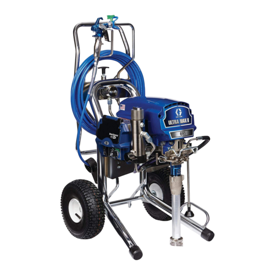
695 Electric Airless Sprayer
For Portable Airless Spraying of Architectural Coatings and Paints.
For professional use only. Not approved for use in explosive atmospheres or hazardous locations.
3300 psi (227 bar, 22.7 MPa) Maximum Working Pressure
Important Safety Instructions
Read all warnings and instructions in this manual and related manuals. Be familiar with the controls
and the proper usage of the equipment. Save these instructions.
ti29576a
3A4399A
EN
Advertisement
Table of Contents

Subscribe to Our Youtube Channel
Related Manuals for Graco 695


Summary of Contents for Graco 695
- Page 1 Operation, Parts, Repair 695 Electric Airless Sprayer 3A4399A For Portable Airless Spraying of Architectural Coatings and Paints. For professional use only. Not approved for use in explosive atmospheres or hazardous locations. 3300 psi (227 bar, 22.7 MPa) Maximum Working Pressure Important Safety Instructions Read all warnings and instructions in this manual and related manuals.
-
Page 2: Table Of Contents
Extension Cords ......7 695 ProContractor Parts ....32 Pails . -
Page 3: Warnings
Warnings Warnings The following warnings are for the setup, use, grounding, maintenance, and repair of this equipment. The exclama- tion point symbol alerts you to a general warning and the hazard symbols refer to procedure-specific risks. When these symbols appear in the body of this manual or on warning labels, refer back to these Warnings. Product-specific hazard symbols and warnings not covered in this section may appear throughout the body of this manual where applicable. - Page 4 Check hoses and parts for signs of damage. Replace any damaged hoses or parts. • This system is capable of producing 3300 psi (227 bar, 22.7 MPa). Use Graco replacement parts or accessories that are rated a minimum of 3300 psi (227 bar, 22.7 MPa).
- Page 5 Do not kink or over-bend the hose. • Do not expose the hose to temperatures or to pressures in excess of those specified by Graco. • Do not use the hose as a strength member to pull or lift the equipment.
-
Page 6: Component Identification
Component Identification Component Identification 695 ProContractor Models: ti18239b Pump Smart Control 3.0 Display ™ Amp Switch (not available on all units) ProConnect ON/OFF Switch Tool Box Pressure Control Rod Pull Feature Spray / Prime / Fast Flush Unit / Serial Tag... -
Page 7: Grounding
Grounding Grounding Pails The equipment must be grounded to reduce the risk of static sparking and electric shock. Electric or static sparking can cause fumes to ignite or explode. Solvent and oil-based fluids: follow local code. Use Improper grounding can cause electric shock. Ground- only conductive metal pails, placed on a grounded sur- ing provides an escape wire for the electric current. -
Page 8: Pressure Relief Procedure
Pressure Relief Procedure Pressure Relief Procedure 3. Remove guard and SwitchTip. Follow the Pressure Relief Procedure whenever you see this symbol. ti2769a This equipment stays pressurized until pressure is 4. Turn pressure to lowest setting. Trigger gun to manually relieved. To help prevent serious injury from relieve pressure. -
Page 9: Setup
Setup Setup 5. Check inlet strainer for clogs and debris. ti17608b 1. Connect Graco airless hose to sprayer. Tighten 6. Fill throat packing nut with Graco TSL to prevent securely. premature packing wear. Do this each time you spray. ti22875a 2. -
Page 10: Startup
Startup Startup Trigger Locked (no spray) Trigger Unlocked (spray) 1. Perform Pressure Relief Procedure, page 8. 6. Hold gun against grounded metal flushing pail. Trig- ger gun and increase fluid pressure 1/2 turn. Flush 2. Turn pressure control to lowest pressure. 1 minute. -
Page 11: Switch Tip Installation
Switch Tip Installation Switch Tip Installation 3. Align tip guard vertically to spray a vertical pattern. 1. Perform Pressure Relief Procedure, page 8. ™ 2. Use spray tip (A) to insert OneSeal (B) into guard (C). Spray 1. Spray test pattern. Increase pressure to eliminate ti13023a heavy edges. -
Page 12: Clear Tip Clog
Clear Tip Clog Clear Tip Clog 2. Engage trigger lock. Return SwitchTip to original position. Disengage trigger lock and continue spray- ing. To avoid serious injury from skin injection do not put ti13034a your hand in front of the spray tip when installing or removing the spray tip and tip guard. -
Page 13: Fast Flush
Fast Flush Fast Flush ™ WatchDog Protection System To flush the hose and gun at an accelerated speed, per- form the following steps: Pump stops automatically when material pail is empty. 1. Perform steps 1 - 3 of Cleanup, page 18. To Activate: 2. -
Page 14: Proguard
ProGuard ProGuard This sprayer protects itself against high and low voltage. Error If the sprayer is plugged into a power source that is too Definition Code low or too high the sprayer will stop operating. Multiple incoming voltage surges detected - unplug sprayer and One of three error codes will be displayed: locate good voltage supply to prevent damage to electronics. -
Page 15: Hose Reel
Hose Reel Hose Reel Moving parts can pinch, cut or amputate fingers and other body parts. To avoid injury from moving parts, be sure to keep your head clear of hose reel while winding up hose. 1. Make sure hose is routed through hose guide. ti13503b ti13502b NOTE: The hose reel can be locked into two positions:... -
Page 16: Digital Tracking System
Digital Tracking System Digital Tracking System Job Gallons 1. Short press DTS button to move to Job Gallons (or liters x 10). Operation Main Menu Short press to move to next display. Press and hold (5 seconds) to change units or reset data. ti22717a NOTE: JOB scrolls past, then the number of gallons ti22719a... -
Page 17: Secondary Menu - Stored Data
Digital Tracking System Secondary Menu - Stored Data Perform Pressure Relief, steps 1 - 4 if they have not already been done. ti22723a Turn power switch on while holding DTS button down. Short press DTS button. W-DOG scrolls past then OFF displays if watchdog switch is OFF. -
Page 18: Cleanup
Cleanup Cleanup 5. Turn prime valve down to DRAIN position and allow flushing fluid to circulate until flushing fluid appears clear. 1. Perform Pressure Relief Procedure (page 8), steps 1 - 4. Remove tip guard from gun. ti22945a NOTE: Use water for water-base material, mineral spirits for oil-base material, or other solvents recom- 6. - Page 19 Cleanup 9. Remove filters from gun and sprayer, if installed. 11. Wipe sprayer, hose and gun with a rag soaked in Clean and inspect. Install filters. water or mineral spirits. ti2776a ti15018a ti13454a 10. If flushing with water, flush again with mineral spir- its, or Pump Armor, to leave a protective coating to prevent freezing or corrosion.
-
Page 20: Maintenance
Maintenance Maintenance Routine maintenance is important to ensure proper operation of your sprayer. Maintenance includes performing routine actions which keep your sprayer in operation and prevents trouble in the future. Activity Interval Inspect/clean sprayer filter, fluid inlet strainer, and gun filter. Daily or each time you spray Inspect motor shield vents for blockage. -
Page 21: Troubleshooting
Troubleshooting Troubleshooting Mechanical/Fluid Flow Perform Pressure Relief Procedure; page 8. WHAT TO CHECK WHAT TO DO TYPE OF PROBLEM If check is OK, go to next check When check is not OK, refer to this column For units with display: Fault condition exists Determine fault correction from table, page 23. - Page 22 Troubleshooting WHAT TO CHECK WHAT TO DO TYPE OF PROBLEM If check is OK, go to next check When check is not OK, refer to this column Pump output is low Pump rod damage Repair pump. See Pump, page 40. Low stall pressure Turn pressure knob fully clockwise.
-
Page 23: Electrical
Troubleshooting Electrical ProGuard Status Light Control Board Status Light Symptom: Sprayer does not run, stops running, or will not shut off. Perform Pressure Relief Procedure; page 8. If there is a voltage supply issue (CODE 04, 08, or 17), the ProGuard status light will blink continuously when the 1. - Page 24 Troubleshooting TYPE OF PROBLEM WHAT TO CHECK HOW TO CHECK Sprayer does not run at all Check transducer or transducer Set sprayer to OFF and disconnect power to connections (control board is not sprayer. Display shows CODE 03 detecting a pressure signal). Check transducer and connections to control board.
- Page 25 Troubleshooting TYPE OF PROBLEM WHAT TO CHECK HOW TO CHECK Sprayer does not run at all Control is commanding motor to run Remove pump and try to run sprayer. If motor runs, but motor shaft does not rotate. check for locked or frozen pump or drive train. Display shows CODE 05 Possibly locked rotor condition, an If sprayer does not run, continue to step 2.
- Page 26 Check Motor Thermal Switch: Unplug thermal motor amp draw is excessive. wires. Set meter to ohms. Meter should read the proper resistance for each unit (see table below). Control board status light blinks 5 times repeatedly ti13140a Resistance Table: 695/240V 0 ohms 3A4399A...
- Page 27 (see table below). Control board status light blinks 6 times repeatedly ti13140a Resistance Table: 695/240V 0 ohms Reconnect thermal device connector to control board socket. Connect power, turn sprayer ON and control knob 1/2 turn clockwise. If sprayer does not run, replace control board.
- Page 28 Troubleshooting TYPE OF PROBLEM WHAT TO CHECK HOW TO CHECK Sprayer does not run at all Excessive current protection Cycle power on and off. enabled Display shows CODE 12 Control board status light blinks 12 times repeatedly Sprayer does not run at all Check the connections above the Set sprayer to OFF and disconnect power to motor...
- Page 29 Troubleshooting Sprayer Will Not Run (See following page for steps) Remove control box cover. Turn sprayer ON. Observe control board status light on control board See Step 1. Do See Step 2. Do (see page 23). you have over you have over 100 VAC No light Repair or...
- Page 30 Troubleshooting STEP 1: STEP 2: Plug power cord in Plug power cord in 200-240V 200-240V and turn switch ON. and turn switch ON. Connect probes to Connect probes to on/off switch. Turn on/off switch. Turn meter to AC Volts. meter to AC Volts. STEP 3: STEP 4: Check motor thermal switch.
- Page 31 Troubleshooting Sprayer Will Not Shut Off 1. Perform Pressure Relief Procedure; page 8. 2. Remove control box cover so the control board Leave prime valve open and power switch OFF. status light can be viewed if available. Troubleshooting Procedure Plumb pressure gauge into paint Mechanical problem: See the proper hose, plug sprayer in, and turn power fluid pump manual for the sprayer for...
-
Page 32: 695 Procontractor Parts
695 ProContractor Parts 695 ProContractor Parts Ref. Torque 40-45 in-lb (4.5 - 5.0 N•m) 9-11 in-lb (1.0 - 1.2 N•m) 200-230 in-lb (22.6 - 25.9 N•m) See page 37. 190-210 in-lb (21.4 - 23.7 N•m) 120-130 in-lb (13.5 - 14.6 N•m) 25-30 ft-lb (33.8 - 40.6 N•m) -
Page 33: 695 Procontractor Parts List
695 ProContractor Parts 695 ProContractor Parts List Ref. Part Description Qty. Ref. Part Description Qty. 24V087 HOUSING, bearing; includes 7, 12, 16C975 PLATE, pivot 15C753 SCREW, mach, hex wash hd 14, 15, 24, 31, 55, 56, 77, 108, 117 105510 WASHER, lock, spring... -
Page 34: Control Box
Control Box Control Box Ref. Torque 10-15 in-lb (1.1 - 1.7 N•m) 40-45 in-lb (4.5 - 5.0 N•m) 22-28 in-lb (2.4 - 3.1 N•m) 200-230 in-lb (22.6 - 25.9 N•m) 30-35 in-lb (3.3 - 3.9 N•m) 15-20 in-lb (1.7 - 2.2 N•m) 2-3 in-lb (0.23 - 0.34 N•m) 75 ref ti29578a... -
Page 35: Control Parts List
CONNECTOR, electrical 26, 60, 131, 142, 144, box not sold sepa- STRAIN RELIEF rately 16T546 16Y762 LABEL, warning, Asia/ANZ 16T547 695/795/1095 Japanese Models 16T541 JUMPER WIRE (Japanese models) 117745 BUSHING, strain relief (Mark VII/Mark X 16X796 LABEL, LCD Models 16X797... -
Page 36: Filter
Filter Filter Ref. Torque 90-110 in-lb (10.1 - 12.4 N•m) 35-45 ft-lb (47.4 - 61.0 N•m) 190-210 in-lb (21.4 - 23.7 N•m) 100-120 in-lb (11.2 - 13.5 N•m) 38-42 ft-lb (51.5 - 56.9 N•m) ti22913c Parts List Ref. Part Description Qty. -
Page 37: Hose Reel And Gun
Hose Reel and Gun Hose Reel and Gun Ref. Torque 130-150 in-lb (14.6 - 16.9 N•m) 25-35 ft-lb (33.8 - 47.4 N•m) 120-130 in-lb (13.5 - 14.6 N•m) 38-42 ft-lb (51.5 - 56.9 N•m) ti14917d Parts List Ref. Part Description Qty. -
Page 38: Spray Gun Parts
Spray Gun Parts pray Gun Parts 16/17 ti8502b Ref. Part Description Qty. Ref. Part Description Qty. 15J696 PIN, trigger (page 40) 289914 HOUSING, assy., FTX 105334 NUT, lock, hex (page 40) 287032 FILTER, 60 mesh 15J464 GUARD, trigger 287033 FILTER, 100 mesh 15J528 GUIDE, spring 287034... -
Page 39: Pump Parts
Pump Parts Pump Parts Ref. Part Description Qty. 201* 179810 SEAL, throat 193046 NUT, packing 203* 192692 V-PACKING, throat, V-Max, UHMWPE, blue 204* 15C987 GLAND, male, throat, 16X450 CYLINDER, pump, Model 16X414 BALL check 105444* Model 16X414 (Stainless steel) 119259† Model 16X418 (Ceramic) 207* 156593... -
Page 40: Repair
5. Unscrew diffuser (15a) from front of gun (1). sleeve. If the sleeve cannot be removed easily, return 6. Remove needle assembly (15b) through front of gun the sleeve and cylinder to a Graco distributor for re- (1). moval. 7. Use a soft brush to clean out internal passages of NOTE: Remove and clean sleeve when repacking pump. -
Page 41: Repair When Pump Is Separated From Sprayer
Repair Repair When Pump is Separated 3. Disassemble intake valve. Clean and inspect o-ring (227). NOTE: A pick may be required to remove From Sprayer o-ring. Disassembling the Pump 1. Remove packing nut (202) and o-ring (228). ti23115a 4. Tap piston rod out of cylinder with a hammer or flip over and tap piston rod out against a bench. - Page 42 Repair 5. Remove piston rod from sleeve, or remove sleeve 7. Remove packings and glands from piston rod. from cylinder. ti3940d 8. Remove throat packings and glands from cylinder. Discard throat packings and glands. ti7572b 6. Unscrew piston valve from piston rod. Clean and inspect parts.
- Page 43 Repair Assembling the Pump 1. Soak all leather packings in SAE 30W oil for 1 hour minimum prior to assembly. Stack male gland (204) on piston rod. Alternately stack UHMWPE (208) and leather (218) packings (note orientation) on piston rod. Install female gland (217). Install piston wiper (216) (note orientation) and backup washer (229) on piston valve, threads are good for four repackings.
- Page 44 Repair 8. Grease top inch or two of piston rod that will go through the cylinder throat packings. ti7579b 9. Grease o-rings (221) and place on sleeve. Slide sleeve/piston rod assembly into bottom of cylinder. ti7581b Replace o-ring (207) if desired. 6.
- Page 45 Repair 10. Reassemble intake valve with new o-ring (227), seat (212) and ball (214). Seat may be flipped over and used on other side. Clean seat thoroughly. ti7569d 12. Torque packing nut (202) to 100 +/- 10 in-lb (11.3 +/-1.1 N•m). 13.
-
Page 46: Technical Data
Technical Data Technical Data 695 Sprayers U.S. Metric Sprayer Maximum Delivery 0.75 gpm 2.8 lpm Maximum Tip Size 0.031 0.031 Fluid Outlet npt(f) 3/8 in. Fluid Inlet 1-5/16-12 un(m) Cycles 226 per gallon 60 per liter Generator Minimum 5000 W... -
Page 47: Graco Standard Warranty
With the exception of any special, extended, or limited warranty published by Graco, Graco will, for a period of twelve months from the date of sale, repair or replace any part of the equipment determined by Graco to be defective. -
Page 48: Graco Information
Original instructions. This manual contains English. MM 3A4399 Graco Headquarters: Minneapolis International Offices: Belgium, China, Japan, Korea GRACO INC. AND SUBSIDIARIES • P.O. BOX 1441 • MINNEAPOLIS MN 55440-1441 • USA Copyright 2016, Graco Inc. All Graco manufacturing locations are registered to ISO 9001. www.graco.com...
Need help?
Do you have a question about the 695 and is the answer not in the manual?
Questions and answers