Table of Contents
Advertisement
Introduction
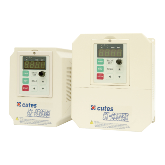
Thank you for choosing the CT-2000ES inverter unit, this inverter unit is suitable for operating squirrel cage
induction motors. Please read this instruction manual carefully before actual usage in order to ensure proper
operation and suit your needs.
Table of Contents
1. Inspection upon receiving...............................................................................................
2. Installation and Storage............................................................
A. Installation ...........................................................................................................
B. Storage...............................................................................................................
C. Outline dimension..................................................................................................
3. Application notes...........................................................................................................
4. Block diagram and wring ...............................................................................................
A. Wiring of main and control circuit ..............................................................................
.
B
Signal circuit.....................................................................
.
C
Connecting the power supply and the AC motor........................
.
R.S.T. for Power source reactor............................................................................
.
F
Standard external connection diagram......................................................................
.
G
Control circuit specification....................................................................................
.
H
Terminal specifications.........................................................................................
5. Operation Test........................................................................
6. Adjust and Function Specification...................................................................................
.
A
Keypad operation................................................................................................
.
B
Display specification.............................................................................................
C. Keypad specification............................................................................................
D. Function Code....................................................................................................
7. Description of alarm display indications .......................................
8. Troubleshooting............................................................................................................
9. Maintenance and Inspection...........................................................................................
10. Standard Specification..................................................................................................
A. 200V series 1 phase..............................................................................................
B. 200V series 3 phase..............................................................................................
C. 400Vseries 3 phase...............................................................................................
11. Function code Table..................................................................................................
12. Modbus Address of Display Data..............................................
13. Series Communication User Manual................................................................................
A. The physical link...................................................................................................
B. Data structure in communication...............................................................................
C. Function code in Modbus........................................................................................
D. Error check generation...........................................................................................
E. Group & global broadcasting....................................................................................
.................................................................
1
................................
.............................
............................
...............................
............................... 41
................................ 51
2
2
2
2
3
4
4
4
4
4
..
5
5
.
6
.
7
.
8
9
.. 11
11
11
11
13
42
. 43
44
44
45
46
... 47
52
52
53
53
56
57
Advertisement
Table of Contents

Related Manuals for CUTES CT-2000ES

Summary of Contents for CUTES CT-2000ES
-
Page 1: Table Of Contents
Introduction Thank you for choosing the CT-2000ES inverter unit, this inverter unit is suitable for operating squirrel cage induction motors. Please read this instruction manual carefully before actual usage in order to ensure proper operation and suit your needs. Table of Contents 1. -
Page 2: Inspection Upon Receiving
1. Inspection upon receiving A. Check that the model, the capacity and power voltage specifications are as ordered. B. Check that no damage has occurred during transportation. C. Check that none of the internal parts have been damaged or have fallen off. D. -
Page 3: Outline Dimension
C. Outline Dimension: CT2002ES-A75 、 C T2002ES-1A5 、 C T2004ES-A75 、 C T2004ES-1A5 CT2002ES-2A2 、 C T2002ES-3A7 、 C T2004ES-2A2 、 C T2004ES-3A7 KEYBAD screw position... -
Page 4: Application Notes
3. Application notes A. Concerning the inverter unit: (1) Do not fit capacitors to the output side of the inverter in order to improve the power ratio. (2) In case of fitting MC between inverter and motor to control motor operation, then the capacity of inverter must be 6 times the capacity of motor. -
Page 5: For Power Source Reactor
D. Instantaneous current and to improve power ratio, it should be fitted the A.C.L. to R.S.T. input side under the following circumstance: a. Where power supply capacity is larger than 500 KVA. b. Using thyrister, phase advance capacitor etc. from the same power supply. A.C.L. -
Page 6: Standard External Connection Diagram
F. Standard external connection diagram ( N o t e : W h i l e e x t e r n a l i s r e q u i r e d f o r D B R , d i s c o n n e c t i n t e r D B R f i r s t ) ( N o t e : W h i l e e x t e r n a l i s r e q u i r e d f o r D B R , d i s c o n n e c t i n t e r D B R f i r s t ) ( N o t e : W h i l e e x t e r n a l i s r e q u i r e d f o r D B R , d i s c o n n e c t i n t e r D B R f i r s t ) ( N o t e : W h i l e e x t e r n a l i s r e q u i r e d f o r D B R , d i s c o n n e c t i n t e r D B R f i r s t ) -
Page 7: Control Circuit Specification
G. Control circuit... -
Page 8: Terminal Specifications
H. Terminal Specifications Connect 3 ∮ A C with Single ∮ 2 00-230V/50,60Hz Main R.S.T AC power input terminal Circuit with 3 ∮ 3 80-460V/50,60Hz U.V.W Inverter output terminal 3-phase induction motor Ground terminal Ground terminal of inverter chassis P.PR Brake resistor connecting Connected proper brake resistor according to terminal... -
Page 9: Operation Test
5. Operational Test A. Check before test Please check the following: (1) Is wiring correct? Check especially the input and output terminals. (2) Is there a short-circuit or ground connection on external wiring? (3) Make sure there is no loosening of screws. (4) Check external sequence control circuit. - Page 10 C. Operational test Test according to the following procedure and be aware of indications. (1) Basic operational test -Operational procedure Connect power supply II. Monitor glittering indicates frequency III. Press either FWD or REV key, motor starts running. It will stop accelerating after reaching set frequency IV.
-
Page 11: Adjust And Function Specification
6. Adjust and Function Specification A. Keypad operation Display PROG READ ▲ STOP ▼ (2) Display specification: 1.Hz、I LED : Hz LED means of recent revolution frequency. I LED means of recent revolution current. Hz and I LED mean of recent revolution voltage on the display. 2.FWD、REV :... - Page 12 3.PROG/SET:FUNC switch: In display mode,PROG/SET key and screen shows Cd00 (General parameter input area).,Press PROG key again and screen shows CE-00 (failure and engineering mode). If pressed PROG key now, screen would return to display mode. SAVE function: In parameter input mode, press PROG/SET key will save new parameter just input.
-
Page 13: Function Code
D. Function Code Cd00 § Set frequency (Settable range 0.5~240 HZ) There are 5 methods to change set frequency. Items A~C are methods of panel key operation, items D-E are methods of external terminal input. A. At display function, press READ and setting (Cd01=0) B. - Page 14 Use PROG key to input procedure (Cd01=0) PROG/ READ ▲ READ Notice: Indicate 7- segment LED flash. § Cd01 Setting procedure of frequency (Selective range 0~6) The function cannot be modified during revolution. Setting procedure of frequency is to select either panel key or external analog signal. Cd01=0 Set frequency on operation panel, as the above items A-C.
- Page 15 § Cd02 Select Main monitor display (Selective range 0~10) The monitor is consisted of four 7-segment LEDs, displays frequency, current and various data by digital number and character. Cd02=0 Display the frequency, LED HZ active Cd02=1 Display the current, LED A active Cd02=2 Display Ultimate speed, Hz and A LED de-active.
- Page 16 § Cd05 Set V/F pattern (Selective range 1~14 The function cannot be modified during revolution There are 11 patterns of V/F slope, as follow: 50HZ 60HZ 50HZ 100HZ 60HZ 120HZ 50HZ 150HZ 60HZ 180HZ 50HZ 200HZ 60HZ 240HZ 87HZ 174HZ 103HZ 206HZ When Cd05=11, V/F slope is determined by Cd57, Cd58...
- Page 17 Cd06 § Motor current rate (Settable range 25~100) Set motor overload protective current, in order to avoid motor failure because of overload. Set value=100, please calculate the following formula: Set Value = Motor rated current / Inverter rated current ×100 Ex.
- Page 18 Cd12, 13, 14 § Speed setting (Settable range 0.5~240) This function has 4 kinds of speed setting The 2 speeds are set from external terminal FR (or RR) which accommodate terminal 3, 5, the setting value cannot exceed the allowed range. Cd12 = 2 speed setting Cd13 = 3...
- Page 19 Cd17 § Upper limiter of frequency (Selective range 10~240) This limiter is used to operate within upper limit frequency of motor Avoid input errors caused by the panel keys and result in mechanical damage. Cd18 § Lower limiter of frequency (Settable range 0.5~100) This limiter is used to operate within lower limit frequency of motor Output Frequency...
- Page 20 Cd22 § Jump frequency width (Settable range 0-6) This function must accommodate Cd20 and Cd21 Cd23 § Braking mode (Settable range 0-3) This function must accommodate Cd24, Cd25, and Cd26. Cd23=0 No DC braking Cd23=1 Stop mode Cd23=2 Start mode Cd23=3 Stop and start mode Cd24 §...
- Page 21 Cd27 § Motor running direction (Settable range 0~2) Fix motor running direction to prevent mechanical damage. Cd27=0 both forward, reverse directions available, stop before changing direction. Cd27=1 both forward and revise directions available, No stop required. Cd27=2 only forward operation is available. Cd27=3 only reverse operation is available.
- Page 22 2. Restart after instantaneous power failure This function if different from free run restart, the inverter control power is maintained above 5V. When it detects low voltage “PLU”, it activates “STOP”, Restart after instantaneous “PLU”. After recovery of voltage, “PLU” are de-active, power failure: no function “STOP”...
- Page 23 Cd31 § Initial factory setting (Settable range 0,1) The function cannot be modified during revolution. Set data to original factory setting. Cd31=0 No change Cd31=1 Initial factory setting, refer to function code table. Note: After this function is active, content value returns to “0”, readable value is always “0”. Cd32、33、34、35 §...
- Page 24 Cd37 § Frequency gain setting (Settable range 20~200) Select ratio of frequency gain Gain setting for external input signals are available using this function. Output Frequency = Set Value ×Frequency Gain ×MAX. Frequency Ex. Under the mode of external voltage (0-10V) frequency setting, frequency gain = 100%, set voltage to 2V,MAX.
- Page 25 Cd40, 41, 42, 43 § Multi-speed setting (Settable range 0.5~240) This function has 8 kinds of speed operation Use external terminal FR (or RR) accommodate DI1, DI2, DI3, DI4 to select different speeds. Refer to the following table: Cd40= 5 step speed setting Cd41= 6 step speed setting...
- Page 26 Cd46 § Speed multiplier (Settable range 0.01~500) The function shows revolution speed multiplied by a scaling factor on the Display. Note: 1. HZ and A LED de-active. 2. RPM = Frequency ×Cd46 3. If the value overflow, it will show “9999”. Cd47 §...
- Page 27 Cd50 § Software version (Read only) This function is to record software version, read only. Cd51 § Motor rated voltage setting Vr (Settable range 10~450) This function cannot be modified during revolution. RMS Setting A. 220V Series: Value of Cd51 = Motor rated voltage / 1 A.
- Page 28 Cd53 § Motor slip differential compensation (Settable range 0~100) This function is to compensate speed variation produced by load variation. This function must accommodate the content of Cd52. Setting value 0-100 in relative slip differential 0.0-10.0% Ex. 60HZ, 4-pole 1700 rpm Synchronous speed = 1800 rpm Full-load speed = 1700 rpm...
- Page 29 Cd56 § Over current stall preventive mode (Settable range 10~200%) This function is to prevent when motor current exceeds stall current from stall. There are 2 kinds of acceleration time slopes when motor acceleration current exceeding stall current occurs: Instantaneous load increase during steady operation and current exceeding over current stall, revolution frequency will drop till current dropped to within stall current level.
- Page 30 Cd59 § Stagnancy of current detected (2~10%) This function accommodate the content of Cd47、Cd48 When Cd47=7,Detect current level over Cd48,input RELAY,but current must be decreased to equal to the value of C48 minus the value of Cd59,RELAY will be opened. Cd60 §...
- Page 31 Cd63 § Start frenquency of auto voltage compensation(Settable range 3.0~20.0HZ) The function cannot be modified during revolution. This function is the point of motion to assume auto compensation voltage start frenquency. This function accommodate the content of Cd03、Cd52 Cd64 § Dynamic braking range (Settable range 0-1) This function cannot be adjusted during revolution.
- Page 32 Output Frequency DC braking frequency Set frequency in stopping Cd24 Start frequency Cd16 Instant DC braking time in starting DC braking time in stopping initial Cd23,Cd26 Cd23,Cd26 field time Output Cd65 voltage Output voltage of set frequency Output voltage of start frequency DC braking voltage Cd25...
- Page 33 Cd68 § Motor vibration compensation (Settable range100~500) The function cannot be modified during revolution. This function is being modified vibration when the motor spin out, set Cd03=0 When the motor vibrates and know the value of vibration by Cd02=10 E.g.: cause Cd02=10 indicate 160 ~ 210,assume Cd68 = 200 Cd69 §...
- Page 34 Cd80=0 RS485 shut down communication interface. Cd80=1 Active RTU Mode(8,n,1). Parameter change is not allowed. Cd80=2 Active RTU Mode(8,n,1). Allow changes on general parameter. Cd80=3 Active RTU Mode(8,n,1). Allow changes on operation instruction and general parameter. Cd81 § RS485 communication address setting (settable range 1-240) This function cannot be modified during revolution Corresponding communication address should be set in advance when active RS485 communication function.
- Page 35 CE05 ~ CE20 § Multi-step function control frequency setting(settable range 0.5~240HZ) Maximum 16 steps. CE05 1 step speed setting CE06 2 step speed setting CE07 3 step speed setting CE08 4 step speed setting CE09 5 step speed setting CE10 6 step speed setting CE11 7 step speed setting...
- Page 36 § CE47 Multi steps function modes selection(settable range0~1) The function cannot be modified during revolution Select operation modes on speed variation when process control switch from previous step to next step. CE47=0 Liner operation CE47=1 Gradually operation. (Perform time can set to zero, when perform time set to 0, perform time will according to CD08, CD09 increase or decrease.
- Page 37 CE48 § Multi steps function operation reset (settable range0~1) The function cannot be modified during revolution Memorized of current operation step and time (in sec) while shut down or power failure. Step and time reset to 0 when set CE48=1. Note: External terminal 6 set to RST function, when RST connect with COM, it will reset the records and steps time to 0.
- Page 38 CE52 § Choice of multi-speed record file (settable range 1~6) The function cannot be modified during revolution The setting cannot be changed while the machine is working. According to the needs of the user, choose different file for the current step, the data CE05~CE36 are stored in the files.
- Page 39 CE63 § Integral gain (settable range 0.0~360.0 sec) PID control and associated gain (I). CE64 § Differential gain (settable range 0.0~10.0 sec) PID control and associated gain (D). CE65 § Integral output limit (settable range 0~100 %) Set % a unit as output limit of the Integral control. 100% is maximum frequency output. CE66 §...
- Page 40 CE80 § PID target acceleration/ deceleration time(settable range 0~25.5) Set PID target acceleration/ deceleration time, setting way is to accelerate 0 to 100%. When PID target is needed to be smoothly curve not pulse wave. CE74 CE62 Proportion DI=11 DI=12 DI=13 Integral Integral...
-
Page 41: Description Of Alarm Display Indications
7. Description of alarm display indications Error Description of fault Item for inspection Processing indication operation Operation error Was the unit operated as indicated Use the correct procedure in the manual Operation error of Switch off the power and then apply Replace the unit internal ROM, RAM again... -
Page 42: Troubleshooting
8. Troubleshooting Description of trouble Possible cause Solution The motor does not Wiring error Refer to the wiring diagram run at all Check the power input wiring Is there a voltage for U.V.W output Wrong settings at operator panel The function code No.04 is as follows 0: Panel key operation 1: External signals Inverter displays fault indication... -
Page 43: Maintenance And Inspection
9. Maintenance and Inspection Maintenance and inspection must be taken under power off. Cautions on maintenance and inspection: (1) Capacitor is charged at high voltage for a while after turning off the power. (Accordingly, start the inspection work at least 5 minutes after turning off the power) (2) Do the work with operator. -
Page 44: Standard Specification
10. STANDARD SPECIFICATION A. 200Vseries 1 phase 0.75 0.375* 0.75* 1.5* Motor rating (KW) ES-A37 ES-A75 ESe-A75 ES-1A5 ESe-1A5 Model CT2001 Rated current (A) Rated capacity (KVA) 0.96 Power supply 1 ψ 2 00~230V ± 1 0% 50HZ ± 5 % or 1 ψ... -
Page 45: 200Vseries 3 Phase
B. 200Vseries 3 phase Motor rating (KW) 0.375 0.75 * 0.75 * * * * Model CT2002 ES-A37 ES-A75 ESe-A75 ES-1A5 ESe-1A5 ES-2A2 ESe-2A2 ES-3A7 ESe-3A7 Rated current (A) 11.1 11.1 Rated capacity (KVA) 0.96 Power supply 3 ψ 2 00~230V ± 1 0% 50HZ ± 5 % 3 ψ... -
Page 46: 400Vseries 3 Phase
C. 400Vseries 3 phase Motor rating (KW) * 0.75 0.75 Model CT2004 ES-A75 ESe-A75 ES-1A5 ESe-1A5 ES-2A2 ESe-2A2 ES-3A7 ESe-3A7 Rated current (A) Rated capacity (KVA) Power supply 3 ψ 3 80~460V ± 1 0% 50HZ ± 5 % or 3 ψ... -
Page 47: Function Code Table
11. Function Code Table Function Detail of Data Initial factory MODBUS setting Address Set frequency 0~240Hz Frequency setting 0: Operation panel Cd00 procedure 1: External IN2 (0-10V) 2: External IN1 (4-20mA) 3: External IN2 (0-10V) hysteresis 4: External IN1 (4-20mA) hysteresis 5: Keypad VR 6: Multi-steps control Select monitor display... - Page 48 Function Detail of Data Initial factory MODBUS setting Address 1~60S DC braking time 0: Both forward and reverse, stop before Operation direction setting changing direction 1: Both forward and reverse, no stop required 2:Forward only 3: Reverse only Restart in instantaneous 0: Without / Without power failure / Free run start 1: With / Without...
- Page 49 Function Detail of Data Initial factory MODBUS setting Address Motor rated frequency Fb 10~240HZ (Fb) FH ≧ F b Stagnancy of current 2~10% detected V/F Frequency FC 0.5~240HZ P.W.M. Frequency 1 0: P.W.M. Frequency set by Cd62 1: 4KHZ 2: 5KHZ 3: 6KHZ 4: 7KHZ 5: 8KHZ...
- Page 50 Function Detail of Data Initial MODBUS factory Address setting CE00 Fault annunciation (The last) None Fault annunciation (Before the CE01 None last) Fault annunciation (The 2 before CE02 None the last) Fault annunciation (The 3 before CE03 None the last) CE04 Input code CE05...
-
Page 51: Modbus Address Of Display Data
CE67 CE62 P gain 0~10.0 CE63 I gain 0.2~1000.0 sec. CE64 Reserved CE65 Output limit 0~100.0 % CE66 PID output limit CE67 PI target value Setting 0~100.0 % CE68 PID delay time 0~10 CE69 PID offset adjust 0~200 CE70 PID output gain 0~25 CE74 P control status selection... -
Page 52: Series Communication User Manual
13. Serial Communications User Manual This product built in with standard RS422/RS485 communicate port, support international standard MODBUS protocol, user can monitor single or many inverters by using PLC, PC, industrial computer or other equipment which support MODBUS protocol A. The physical link The wiring of this product can use either RS422 (4 wires) or RS485 (2wires), by jumper. -
Page 53: Data Structure In Communication
B. Data structure in communication This product support MODBUS RTU and MODBUS ASCII protocol. In ASCII mode, every byte of the data will transfer to two ASCII code. Ex. If byte data is 63H, it will be 36H, 33H in ASCII code. (1) Hex to ASCII code transfer table Char ‘... - Page 54 Query Field Name Example (hex) ASCII code RTU 8-Bit Field Header ‘ : ’ (Colon) None Slave Address 1111 0110 Function 0000 0011 Start Address Hi 0000 0000 Start Address Lo 1000 0000 No. of Register Hi 0000 0000 No. of Register Lo 0000 0011 Error Check LRC (2 chars)
- Page 55 (2) Function 06H:preset signal register Presets a value into a single holding register (4 x reference). When broadcast, the function presets the same register reference in all attached slaves. The maximum parameters supported by various controller models are listed on page. Ex.
-
Page 56: Error Check Generation
D. Error check Generation (1) LRC Generation Add all bytes in the message, excluding the starting colon and ending CRLF. Add them into an eight-bit field, so that carries will be discarded. Subtract the final field value from FF hex (all 1's), to produce the ones complement. Add 1 to produce the two's-complement. -
Page 57: Group & Global Broadcasting
E. Group and Global Broadcast (1) Group Broadcast User can use this function to control certain group of inverter at the same time. When master send out group address data, the slave inverters will react when receive order, but will not send any signal back to master. (2) Global Broadcast User can use this function to control all inverters at the same time.
Need help?
Do you have a question about the CT-2000ES and is the answer not in the manual?
Questions and answers