Table of Contents
Advertisement
Quick Links
Advertisement
Table of Contents

Related Manuals for Leica CS10


Summary of Contents for Leica CS10
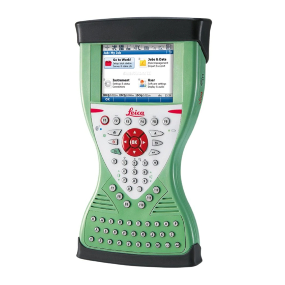
- Page 1 Leica CS10/CS15 & GS Sensors User Manual Version 8.0 English...
- Page 2 Product The model and serial number of your product are indicated on the type plate. Identification Always refer to this information when you need to contact your agency or Leica Geosystems authorised service centre. Trademarks • Windows is a registered trademark of Microsoft Corporation in the United States and other countries ®...
- Page 3 Add all products that you and your company own and explore your world of Leica Geosystems: View detailed information on your prod- ucts and update your products with the latest software and keep up- to-date with the latest documentation.
-
Page 4: Table Of Contents
Connecting to a Personal Computer 4.1.14 Enabling WiFi in WinCE Power Functions Batteries 4.3.1 Operating Principles 4.3.2 Changing the Battery 4.3.3 Charging the Battery Working with the Memory Device LED Indicators on CS10/CS15 CS10/CS15 & GS Sensors, Table of Contents... - Page 5 6.4.2 Accuracy 6.4.3 Technical Data Antennas Technical Data Conformity to National Regulations 6.6.1 CS10 6.6.2 CS15 6.6.3 CTR16/CTR17 6.6.4 GS08plus 6.6.5 GS12 Software Licence Agreement Appendix A Pin Assignments and Sockets CS10/CS15 GS08plus CS10/CS15 & GS Sensors, Table of Contents...
-
Page 6: Safety Directions
Important paragraphs which must be adhered to in practice as they enable the product to be used in a technically correct and efficient manner. CS10/CS15 & GS Sensors, Safety Directions... -
Page 7: Definition Of Use
The following advice is only valid for battery charger, power adapter and car adapter. Environment Suitable for use in dry environments only and not under adverse conditions. CS10/CS15 & GS Sensors, Safety Directions... -
Page 8: Responsibilities
• To ensure that it is used in accordance with the instructions. • To be familiar with local regulations relating to safety and accident prevention. • To inform Leica Geosystems immediately if the product and the application becomes unsafe. • To ensure that the national laws, regulations and conditions for the operation of radio transmitters are respected. -
Page 9: Hazards Of Use
(>1 kg) safely. If the product is used with accessories, for example masts, staffs, poles, you may WARNING increase the risk of being struck by lightning. Precautions: Do not use the product in a thunderstorm. CS10/CS15 & GS Sensors, Safety Directions... - Page 10 Protection is as described for non-metallic structures, but the air terminals can be connected directly to the conducting structure without the need for down conduc- tors. Air terminal arrangement, plan view a) Antenna b) Support structure c) Air terminal GS_039 CS10/CS15 & GS Sensors, Safety Directions...
- Page 11 • Touching live components • Using the product after incorrect attempts were made to carry out repairs Precautions: Do not open the product. Only Leica Geosystems authorised service centres are enti- tled to repair these products. The following advice is only valid for power adapter or docking station.
- Page 12 Always prevent access to the product by unauthorised personnel. Product-specific treatment and waste management information can be received from your Leica Geosystems distributor. Only Leica Geosystems authorised service centres are entitled to repair these prod- WARNING ucts. CS10/CS15 & GS Sensors, Safety Directions...
-
Page 13: Electromagnetic Compatibility Emc
WARNING Although the product meets the strict regulations and standards which are in force in this respect, Leica Geosystems cannot completely exclude the possibility that other equipment may be disturbed. There is a risk that disturbances may be caused in other equipment if the product is... -
Page 14: Fcc Statement, Applicable In U
• Connect the equipment into an outlet on a circuit different from that to which the receiver is connected. • Consult the dealer or an experienced radio/TV technician for help. Changes or modifications not expressly approved by Leica Geosystems for compliance WARNING could void the user's authority to operate the equipment. - Page 15 Leica Geosystems AG interference received, CH-9435 Heerbrugg including interference that S.No.:123456 Manufactured: 20XX may cause undesired Art.No.:788855 operation. Made in Switzerland 0012772_001 003053_002 Labelling GS05, GS06 CS_012 Labelling GS08plus 005039_001 Labelling internal battery GEB212 005044_001 CS10/CS15 & GS Sensors, Safety Directions...
- Page 16 ANSI/IEEE C95.1-1992 and had been tested in accordance with the measurement procedures specified in IEEE Std. 1528-2003. This Class (B) digital apparatus complies with Canadian ICES-003. WARNING Cet appareil numérique de la classe (B) est conforme à la norme NMB-003 du Canada. CS10/CS15 & GS Sensors, Safety Directions...
-
Page 17: Description Of The System
The CGR15 is a receiver-only UHF radios that can be mounted no internal radio directly onto the CS15. The CGR15 transforms the CS15 into a fully flexible RTK rover that supports both GSM/GPRS and UHF commu- nications. CS10/CS15 & GS Sensors, Description of the System... -
Page 18: System Concept
• A message will appear when the upload is complete. Ensure that a Leica SD card is inserted into the CS field controller before starting the upload. CS10/CS15 & GS Sensors, Description of the System... - Page 19 Refer to the Leica Viva TechRef (Connec- tions.. - GPS connection wizard). • Start the upload. Refer to the Leica Viva GNSS Getting Started Guide (Appendix B Uploading System Files). • A message will appear when the upload is complete.
-
Page 20: Power Concept
Available capacity: 1 GB. While other SD cards can be used, Leica Geosystems recommends to only use Leica SD cards and is not responsible for data loss or any other error that can occur while using a non-Leica card. ... -
Page 21: Container Contents
GAD34 arm 3 cm g) Antennas of device h) GAD32 telescopic antenna rod i) GEB371 battery j) GFU device such as radio k) Manual & USB documentation card l) Height hook 003276_003 CS10/CS15 & GS Sensors, Description of the System... - Page 22 GAD108 arm i) GAT21 antenna for CGR radio j) GS14/GS12/GS08plus antenna k) CGR radio l) GDC221 car adapter m) GHT63 clamp n) Manual & USB documentation card o) GAT1/GAT2 radio antenna 004601_002 CS10/CS15 & GS Sensors, Description of the System...
- Page 23 GEB211/GEB212 batteries c) GRT146 carrier d) Tribrach e) Allen key f) Viva Uno instrument (CS field controller with GS GNSS antenna cap) g) GHT61 hand strap h) Antenna and GAD31 adapter SYS13_32 CS10/CS15 & GS Sensors, Description of the System...
-
Page 24: Cs Components
Hand strap bottom clips b) Hand strap c) Battery compartment d) Hand strap top clips e) Slots f) Slot cover g) Stylus h) GS05 contacts i) SIM card slot j) SD card slot 0012572_001 CS10/CS15 & GS Sensors, Description of the System... -
Page 25: Cs15
Hand strap bottom clips b) Hand strap c) Battery compartment d) Hand strap top clips e) Slots f) Slot cover g) Stylus h) GS06 contacts i) SIM card slot j) SD card slot 0012597_001 CS10/CS15 & GS Sensors, Description of the System... -
Page 26: Docking Station Components
GEV223 data cable CS_020 GS08plus/GS12 Components GS08plus/GS12 components a) ON/OFF button b) LEDs c) LEMO port including USB port d) Mechanical Reference Plane (MRP) e) Clip-on contacts (only GS12) f) Battery compartment 004097_001 CS10/CS15 & GS Sensors, Description of the System... -
Page 27: User Interface
Correspond to six softkeys that appear on the bottom of the F1-F6 screen when the screen is activated. Function keys User definable keys to execute chosen commands or access F7-F12 chosen screens. Alpha keys To type letters. Numeric keys To type numbers. CS10/CS15 & GS Sensors, User Interface... - Page 28 If CS10/CS15 in stand-by mode: Turns on CS10/CS15 when held < 2 s. If CS10/CS15 already on: • Puts CS10/CS15 into stand-by mode when held < 2 s. Refer to "Stand-by". • Turns to Power Options menu when held for 2 s. Refer to "Power Options menu".
-
Page 29: Operating Principles
To accept data entered into an editable Tap on the screen outside of the editable field and exit the edit mode field. To open a context-sensitive menu Tap on the item and hold for 2 s. CS10/CS15 & GS Sensors, User Interface... -
Page 30: Operation
Use an external battery such as GEB371 to ensure operation for a full day. Equipment setup - GS08plus/GS12/ GS14 a) GS08plus/GS12/GS14 instrument b) Height hook c) GRT146 carrier d) Tribrach e) Tripod f) CS field controller g) GHT61 hand strap h) GEB211/GEB212 battery i) SD card 0012598_001 CS10/CS15 & GS Sensors, Operation... - Page 31 To hang the CS field controller on the leg, use the hook on the rear of the tripod leg, use the hook on the hand unit. Or place the instrument in the strap. Refer to the CS10/CS15 User container. Manual. Insert the height hook into the carrier.
-
Page 32: Setting Up As A Real-Time Base
GHT58 tripod bracket h) GFU radio modem i) SD card j) CS field controller k) GEB211 / GEB212 battery l) GEB371 external battery m) GEV205 Y-cable for 0012599_001 GS08plus instrument, GEV264 Y-cable for GS14 instrument CS10/CS15 & GS Sensors, Operation... - Page 33 Screw the radio antenna Measure the antenna Press the ON/OFF onto the antenna arm. height using the height button on the instru- hook. ment for at least 2 s to switch on the instru- ment. CS10/CS15 & GS Sensors, Operation...
- Page 34 Connect the radio antenna to the radio using the second 1.2 m antenna cable. Press the ON/OFF button on the instru- ment for at least 2 s (GS25: 3 s) to switch on the instrument. CS10/CS15 & GS Sensors, Operation...
-
Page 35: Setting Up As A Real-Time Rover
Equipment setup - GS08plus a) GS08plus instrument b) Pole c) CGR10 radio d) Grip for pole e) GHT62 holder f) GEB211/GEB212 battery g) SD card h) CS field controller i) GEB211/GEB212 battery 002498_004 CS10/CS15 & GS Sensors, Operation... - Page 36 Insert the data storage device (only GS14/GS15) and the batteries into the GS12/GS14/GS15/GS08plus. Press ON/OFF button on the GS12/GS14/GS15/GS08plus to switch on. Screw the GS12/GS14/GS15/GS08plus to the top of the pole. CS field controller and GS12/GS14/GS15/GS08plus are connected via Bluetooth. CS10/CS15 & GS Sensors, Operation...
-
Page 37: Setting Up Viva Uno
Description The Viva Uno instrument consists of the CS field controller (CS10/CS15) and the GS GNSS antenna cap (GS05/GS06) attached to the CS field controller. The CS field controller with the GS GNSS antenna cap attached, clips to the tripod leg. - Page 38 Connect the antenna cable to the external GNSS antenna and to the GS GNSS antenna cap. When you are using the external GNSS antenna, ensure that you selected the correct Rover antenna (AS05 Tripod GHM). Press ON/OFF button on the CS field controller to switch on. CS10/CS15 & GS Sensors, Operation...
-
Page 39: Fixing The Field Controller To A Holder And Pole
TS_056 After the field controller is placed onto the mounting plate, ensure that the locking pin is put into the locked position. To lock the locking pin, push the locking pin to the right. TS_054 CS10/CS15 & GS Sensors, Operation... -
Page 40: Fixing The Display Foil To The Cs
Do not use sharp objects! In case of remaining dust or grease under the display foil or the need to replace the display foil, lift it again with some adhesive tape. CS10/CS15 & GS Sensors, Operation... -
Page 41: Fixing A Hand Strap To The Cs
Description Press the screwdriver end of the supplied stylus on the quarter-turn screws and loosen them. Remove the slot cover. Reattach the slot cover with the stylus, making sure the quarter-turn screws are seated. CS10/CS15 & GS Sensors, Operation... -
Page 42: Inserting And Removing A Sim Card
0012604_001 Description The SIM card is inserted into a slot inside the top of the CS10/CS15. Loosen the screws inside the slot cover on top of the CS10/CS15 using the screwdriver end of the stylus. Detach the slot cover from the CS10/CS15. -
Page 43: Setting Up As Handheld Gnss
4.1.11 Setting up as Handheld GNSS The setup GS05/CS10 is identical to the setup GS06/CS15. For simplicity, the setup GS05/CS10 is used in the following. Attaching the GS05 to the CS10 step-by-step 0012605_001 Step Description Detach the slot cover from the CS10. -
Page 44: Connecting To A Personal Computer
Insert the Leica Viva Series USB card. Run the SetupViva&GR_USB_XX.exe to install the drivers necessary for Leica Viva devices. Depending on the version (32bit or 64bit) of the oper- ating system on your PC, you have to select between the three setup files following: •... - Page 45 Devices. The folders of the data storage device can be found in StorageCard. For PCs with Windows Vista or Windows 7/Windows 8 operating system: Windows Mobile Device Center starts up automatically. If does not start automatically, start Windows Mobile Device Center. CS10/CS15 & GS Sensors, Operation...
-
Page 46: Enabling Wifi In Wince
Windows CE and settings of all installed software) Turn on To turn on the instrument press and hold the ON/OFF button for 2 s. GS08plus/GS12 Turn off To turn off the instrument press and hold the ON/OFF button for 2 s. GS08plus/GS12 CS10/CS15 & GS Sensors, Operation... -
Page 47: Batteries
+10 °C to +20 °C/+50 °F to +68 °F if possible. • It is normal for the battery to become warm during charging. Using the chargers recommended by Leica Geosystems, it is not possible to charge the battery once the temperature is too high. -
Page 48: Charging The Battery
Refer to "LED indicators" for information about the power LED. Charge battery for To charge the batteries for GS08plus/GS12, use the Leica Geosystems chargers GKL311 GS08plus/GS12 or GKL341. Refer to the GKL311 or GKL341 User Manual for further information. -
Page 49: Working With The Memory Device
Step Description The SD card is inserted into a slot inside the top of the CS10/CS15. Loosen the screws inside the slot cover on top of the CS10/CS15 using the screwdriver end of the stylus. Detach the slot cover from the CS10/CS15. -
Page 50: Led Indicators On Cs10/Cs15
The battery is being charged. power is very low. The battery should be changed. flashing red power is very low. The battery is being charged. CS10/CS15 & GS Sensors, Operation... -
Page 51: Led Indicators On Ctr16/Ctr17
CTR16/CTR17 is in configuration mode purple radio is connecting. blue radio has connected. flashing blue data is being transferred. the CTR16/CTR17 is not ready to be used. CS10/CS15 & GS Sensors, Operation... -
Page 52: Led Indicators On Gs08Plus/Gs12
Power is 20% - 5%. flashing red Power is low (<5%). The remaining time for which enough power is avail- able depends on the type of survey, the temperature and the age of the battery. CS10/CS15 & GS Sensors, Operation... -
Page 53: Care And Transport
Shipping When transporting the product by rail, air or sea, always use the complete original Leica Geosystems packaging, transport container and cardboard box, or its equivalent, to protect against shock and vibration. Shipping, transport When transporting or shipping batteries, the person responsible for the product must... -
Page 54: Cleaning And Drying
Cables and plugs Keep plugs clean and dry. Blow away any dirt lodged in the plugs of the connecting cables. Connectors with Wet connectors must be dry before attaching the dust cap. dust caps CS10/CS15 & GS Sensors, Care and Transport... -
Page 55: Technical Data
Nominal voltage 12 V DC ( Voltage range 10.5 V-28 V Internal battery Type Battery Voltage Capacity Operating time, typical CS10/CS15 Li-Ion 7.4 V GEB212: 2.6 Ah 10 h * Operating time depends on use of wireless communication devices. CS10/CS15 & GS Sensors, Technical Data... - Page 56 115200 Parity: None Terminator: CR/LF Data bits: Stop bits: Ports Type 8 pin LEMO-1 DSUB9 USB A USB Mini Docking station Host contacts CS10/CS15 For power and/or For communication For power and/or communication communication CS10/CS15 & GS Sensors, Technical Data...
-
Page 57: Gs05/Gs06 Technical Data
40 cm. The measurement of accuracy is compliant with ISO 17123-8. Differential phase Type Horizontal Vertical in post-processing Static 5 mm + 0.5 ppm 10 mm + 0.5 ppm Kinematic 10 mm + 1 ppm 20 mm + 1 ppm CS10/CS15 & GS Sensors, Technical Data... -
Page 58: Technical Data
IP67 (IEC 60529) Dust tight Protected against water jets Waterproof to 1 m temporary immersion Humidity Protection Up to 100 % The effects of condensation are to be effectively counteracted by periodically drying out the antenna. CS10/CS15 & GS Sensors, Technical Data... -
Page 59: Ctr16/Ctr17 Technical Data
IP67 (IEC 60529) Dust tight Protected against water jets Waterproof to 1 m temporary immersion Humidity Protection Up to 100 % The effects of condensation are to be effectively counteracted by periodically drying out the CTR16/CTR17. CS10/CS15 & GS Sensors, Technical Data... -
Page 60: Gs08Plus/Gs12
Up to 16 simultaneously on L1, L2 and L5 (GPS) + up to 14 simultane- ously on L1 and L2 (GLONASS) + up to 14 simultaneously on E1, E5a, E5b and Alt-BOC (Galileo) + up to four SBAS (EGNOS, WAAS, MSAS, GAGAN) CS10/CS15 & GS Sensors, Technical Data... -
Page 61: Accuracy
3.5 mm + 0.4 ppm Differential phase Type Horizontal Vertical in real-time Single Baseline (<30 km) 8 mm + 1 ppm 15 mm + 1 ppm Network RTK 8 mm + 0.5 ppm 15 mm + 0.5 ppm CS10/CS15 & GS Sensors, Technical Data... -
Page 62: Technical Data
The table gives a description and the intended use of the GS08plus/GS12. Type Description GS08plus L1, L2 GPS, GLONASS With CS10 or CS15 field controller SmartTrack antenna GS12 L1, L2, L5 GPS, GLONASS, Galileo With CS10 or CS15 field controller... - Page 63 Protected against continuous immersion in water Tested for 2 h in 1.40 m depth Humidity Protection Up to 100 % The effects of condensation are to be effectively counteracted by periodically drying out the antenna. CS10/CS15 & GS Sensors, Technical Data...
-
Page 64: Antennas Technical Data
Up to 100 % The effects of condensation are to be effectively counter- acted by periodically drying out the antenna. Cable length Separation distance from instrument to antenna Supplied cable lengths [m] GS05/GS06 AS05 CS10/CS15 & GS Sensors, Technical Data... -
Page 65: Conformity To National Regulations
6.6.1 CS10 Conformity to • Hereby, Leica Geosystems AG, declares that the product CS10 is in compliance with national regulations the essential requirements and other relevant provisions of Directive 1999/5/EC and other applicable European Directives. The declaration of conformity can be consulted at http://www.leica-geosystems.com/ce. -
Page 66: Cs15
• FCC Part 15, 22 and 24 (applicable in US) national regulations • Hereby, Leica Geosystems AG, declares that the product CS15 is in compliance with the essential requirements and other relevant provisions of Directive 1999/5/EC and other applicable European Directives. The declaration of conformity can be consulted at http://www.leica-geosystems.com/ce. -
Page 67: Ctr16/Ctr17
• FCC Part 15 (applicable in US) national regulations • Hereby, Leica Geosystems AG, declares that the product CTR17 is in compliance with the essential requirements and other relevant provisions of Directive 1999/5/EC and other applicable European Directives. The declaration of conformity can be consulted at http://www.leica-geosystems.com/ce. -
Page 68: Gs08Plus
• FCC Part 15 (applicable in US) national regulations • Hereby, Leica Geosystems AG, declares that the product GS08plus is in compliance with the essential requirements and other relevant provisions of Directive 1999/5/EC and other applicable European Directives. The declaration of conformity can be consulted at http://www.leica-geosystems.com/ce. -
Page 69: Gs12
• FCC Part 15 (applicable in US) national regulations • Hereby, Leica Geosystems AG, declares that the product GS12 is in compliance with the essential requirements and other relevant provisions of Directive 1999/5/EC. The declaration of conformity can be consulted at http://www.leica-geosystems.com/ce. -
Page 70: Software Licence Agreement
Leica Geosystems. Such software is protected by copyright and other laws and its use is defined and regulated by the Leica Geosystems Software Licence Agreement, which covers aspects such as, but not limited to, Scope of the Licence, Warranty, Intellectual Property Rights, Limitation of Liability, Exclusion of other Assurances, Governing Law and Place of Jurisdiction. -
Page 71: Appendix A Pin Assignments And Sockets Cs10/Cs15
In or out Power input, 10.5 V-28 V TRM_ON/USB_ID RS232, general purpose signal In or out Sockets 9 pin RS232: RS232, 9 pin, DB9 8 pin LEMO-1: LEMO-1, 8 pin, LEMO EGI.1B.308.CLN CS10/CS15 & GS Sensors, Pin Assignments and Sockets... -
Page 72: Gs08Plus
USB data line In or out Signal ground RS232, receive data PIN_001 RS232, transmit data Identification pin In or out Power input, 10.5 V-28 V TRM_ON/USB_ID RS232, general purpose signal In or out CS10/CS15 & GS Sensors, Pin Assignments and Sockets... - Page 73 CS10/CS15 & GS Sensors, Pin Assignments and Sockets...
- Page 74 772386-8.0.0en Original text Printed in Switzerland © 2016 Leica Geosystems AG, Heerbrugg, Switzerland Leica Geosystems AG Heinrich-Wild-Strasse CH-9435 Heerbrugg Switzerland Phone +41 71 727 31 31 www.leica-geosystems.com...
Need help?
Do you have a question about the CS10 and is the answer not in the manual?
Questions and answers