Keithley 3706A User Manual
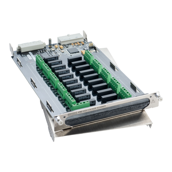
10-channel high voltage multiplexer card
Hide thumbs
Also See for 3706A:
- Quick start manual (18 pages) ,
- Reference manual (936 pages) ,
- Firmware release notes (17 pages)

Related Manuals for Keithley 3706A


Summary of Contents for Keithley 3706A
- Page 1 Model 3762 10-Channel High Voltage Multiplexer Card User’s Manual 3762-900-01 Rev. A / July 2017 *P3762-900-01A* 3762-900-01A...
- Page 2 Keithley Instruments is strictly prohibited. These are the original instructions in English. All Keithley Instruments product names are trademarks or registered trademarks of Keithley Instruments. Other brand names are trademarks or registered trademarks of their respective holders.
-
Page 3: Safety Precautions
Keithley Instruments products are designed for use with electrical signals that are measurement, control, and data I/O connections, with low transient overvoltages, and must not be directly connected to mains voltage or to voltage sources with high transient overvoltages. - Page 4 (note that selected parts should be purchased only through Keithley Instruments to maintain accuracy and functionality of the product). If you are unsure about the applicability of a replacement component, call a Keithley Instruments office for information.
-
Page 5: Table Of Contents
Table of contents Introduction ....................... 1-1 Your multiplexer card ......................1-1 System switch / multimeter card compatibility ..............1-1 Extended warranty ....................... 1-2 Series 3700A documentation ....................1-2 Contact information ......................1-2 General information ......................1-2 Specifications ........................1-3 Installation and connections ..................2-1 Handling precautions ...................... - Page 6 Table of contents Model 3762 10-Channel High Voltage Multiplexer Card User's Manual Index ........................... I-1...
-
Page 7: Introduction
All plug-in cards compatible with the 3706A mainframe, plus the following card models: • 3760 • 3761 • 3762 • 3765 The 3762 is designed for use only with the Model 3706A System Switch / Multimeter. Using the 3762 with the Model 3706 mainframe can cause unpredictable behavior. -
Page 8: Extended Warranty
If you have any questions after you review the information in this documentation, please contact your local Keithley Instruments office, sales partner, or distributor. You can also call the corporate headquarters of Keithley Instruments (toll-free inside the U.S. and Canada only) at 1-800-935-5595, or from outside the U.S. -
Page 9: Specifications
1000 V/1 ma. The relay drive current is 80 mA per channel (40 mA per relay). The 3762 is field installable in an appropriate Keithley Series 3700A Systems Switch Multimeter (for Ω and less example, Model 3700A). With the isolation between each channel being greater than 10 than 10 pF, each channel is well insulated from cross-channel noise and interference. -
Page 10: Installation And Connections
Section 2 Installation and connections In this section: Handling precautions ............... 2-1 Unpack and inspect ..............2-1 Card connectors ............... 2-2 Card installation ............... 2-2 Handling precautions Make sure to handle the 3762 carefully. Always grasp the multiplexer card by the side edges or covers. -
Page 11: Card Connectors
Section 2: Installation and connections Model 3762 10-Channel High Voltage Multiplexer Card User's Manual Card connectors All connections will need to be made before the card is installed in the mainframe. Because the card is rated at higher voltage than the mainframe, no backplane connectors are provided internal to the card. - Page 12 Model 3762 10-Channel High Voltage Multiplexer Card User's Manual Section 2: Installation and connections Perform the following steps to install a switching card into the instrument mainframe: 1. Turn the instrument off and disconnect the power line cord and any other cables connected to the rear panel.
- Page 13 Section 2: Installation and connections Model 3762 10-Channel High Voltage Multiplexer Card User's Manual 3762-900-01 Rev. A / July 2017...
-
Page 14: General Operation
This section provides information needed to use the 3762 10-channel 2 Form A High-Voltage Card with the Model 3706A system switch mainframe. Once the card is installed in the mainframe, refer to the Series 3700A System Switch/Multimeter Reference Manual for complete operating instructions. -
Page 15: Wire Selection And Preparation
Section 3: General operation Model 3762 10-Channel High Voltage Multiplexer Card User's Manual Follow these recommendations before and after applying power to the equipment: 1. Do not exceed the 3762 maximum voltage as defined in the specifications. 2. Do not exceed the 3762 maximum common mode voltage of 1000 V as defined in the specifications. -
Page 16: Wiring
Model 3762 10-Channel High Voltage Multiplexer Card User's Manual Section 3: General operation Wiring Because of the high impedance of the board, take special care when handling and using to prevent degradation of performance. Handle the board by the edges to avoid contaminating it with dirt or body oil. -
Page 17: Operation Considerations
In some cases, multiple sources and measuring instruments are connected to a single device. Switching allows automating the testing of multiple devices (for more information about switching, go to the Keithley Instruments website (http://www.tek.com/keithley) and search for Switching Handbook). -
Page 18: Reactive Loads
Section 4: Operation considerations Model 3762 10-Channel High Voltage Multiplexer Card User's Manual Reactive loads The 3762 is specified for resistive loads only. Since reactive loads can cause excessive currents and voltages, current surge limiting (for capacitive loads) and voltage clamping (for inductive loads) are required to prevent damaging the relays and external circuitry. -
Page 19: Inductive Loads
Model 3762 10-Channel High Voltage Multiplexer Card User's Manual Section 4: Operation considerations Inductive loads Inductive reaction voltage, L(di/dt), must be less than 1000 V. Typical clamping circuits are shown in the next figures. Also, consider the maximum load of 10 VA when determining the voltage limit. For example, when switching 40 mA, the voltage must be limited to 250 V (V = 10 VA/40 mA) and the clamping resistor calculation in the next figure would be: R = V/I = 250 V/40 mA = 6.25 kΩ... -
Page 20: Typical Applications
The 3762 can monitor high voltages from 10 different devices under test (DUT), switch a high-voltage source to 10 separate DUTs, or connect multiple DUTs to multiple sources.For more information about some typical applications and graphics showing typical configurations, refer to the Keithley Instruments Switching Handbook. In some cases, multiple sources and measuring instruments are connected to a single device. -
Page 21: Guarded Application
Section 5: Typical applications Model 3762 10-Channel High Voltage Multiplexer Card User's Manual Guarded application Non-driven guarded measurements are made with the set up shown in the next figure. The jumper is installed to provide a guard that completely encloses HI and LO. This guards HI and LO from other channels on the card for improved channel isolation. -
Page 22: Four-Wire Application
Model 3762 10-Channel High Voltage Multiplexer Card User's Manual Section 5: Typical applications Four-wire application Connecting multiple DUTs to one instrument using either a Kelvin technique or external sense as with a Source Measure Unit (SMU), requires two cards operating in four-pole mode. This is shown in the next figure. -
Page 23: Switch Terminology
Section 6 Switch terminology In this section: Switch terminology ..............6-1 Switch terminology The terms Form A, B, or C are used in switch terminology, throughout this manual, and are described as follows: • Form A is simply a single-pole normally-open (SPNO) switch (see next figure) A double-pole switch normally-open is classified as a 2 Form A. - Page 24 Index Cables • 4-1 Safety hazards • 3-1 Capacitive loads • 4-2 Series 3700A documentation • 1-2 Card connectors • 2-2 Shielded application • 5-1 Card installation • 2-2 Specifications • 1-3 Contact information • 1-2 Switch terminology • 6-1 System switch / multimeter card compatibility •...
- Page 25 All Keithley trademarks and trade names are the property of Keithley Instruments. All other trademarks and trade names are the property of their respective companies. Keithley Instruments Corporate Headquarters • 28775 Aurora Road • Cleveland, Ohio 44139 • 440-248-0400 • Fax: 440-248-6168 • 1-800-935-5595 • www.tek.com/keithley 3/17...
Need help?
Do you have a question about the 3706A and is the answer not in the manual?
Questions and answers