Table of Contents
Advertisement
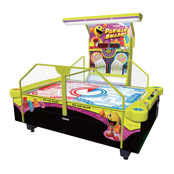
PAC-MAN SMASH
Operation Manual
The actual product may differ slightly from the illustrations in this Operation Manual.
To ensure safe operation of the machine, be sure to read this Operation Manual before use.
Keep this Operation Manual in a safe place for quick access whenever needed.
NAMCO BANDAI Games Inc.
M259_Intro_EN.indd 2
2/5/2013 7:39:59 AM
Advertisement
Table of Contents

Related Manuals for NAMCO PAC-MAN SMASH


Summary of Contents for NAMCO PAC-MAN SMASH
- Page 1 The actual product may differ slightly from the illustrations in this Operation Manual. To ensure safe operation of the machine, be sure to read this Operation Manual before use. Keep this Operation Manual in a safe place for quick access whenever needed. NAMCO BANDAI Games Inc. M259_Intro_EN.indd 2 2/5/2013 7:39:59 AM...
- Page 2 Introduction Thank you very much for purchasing PAC-MAN SMASH (referred to as “the machine” in this manual). This Operation Manual describes: • How to safely install, move, transport, operate, service and dispose of the machine. • How to make full use of the machine’s functions and operate it correctly.
-
Page 3: Safety Precautions -Be Sure To Read To Ensure Safe Operation
1. Safety Precautions -Be sure to read to ensure safe operation- Instructions to the Owner If you delegate the work for installing, moving, transporting, operating, servicing or disposing the machine to other people, ensure that these people read the relevant sections of this operation manual carefully before starting work, and observe the corresponding precautions. -
Page 4: Critical Safety Precautions
Inspection” on page 35.) and service (See “8B Service” on page 109.). Omitting these inspections or service may result in an accident. Use the consumables and service parts (including screws) that are specifi ed by NAMCO BANDAI Games Inc. To order parts, contact your distributor. -
Page 5: Machine Warning Labels
1. Safety Precautions -Be sure to read to ensure safe operation- Machine Warning Labels The warning labels attached to the machine contain important information for ensuring safety. Be sure to observe the following. • To ensure that the warning labels attached to the machine are always clearly visible, install the machine in an appropriate location with ample illumination and keep the labels clean at all times. - Page 6 1. Safety Precautions -Be sure to read to ensure safe operation- Caution sticker Do Not Approach Net Part No.: 461-771 Warning sticker Service B (EXP) Part No.: 461-539 Warning sticker Service B (EXP) Part No.: 461-539 M259_01_EN.indd 4 M259_01_EN.indd 4 2/5/2013 7:41:26 AM 2/5/2013 7:41:26 AM...
- Page 7 1. Safety Precautions -Be sure to read to ensure safe operation- (When transporting the side tower cabinet) Warning sticker Installation and Transport Part No.: 461-770 Warning sticker Installation and Transport Part No.: 461-770 M259_01_EN.indd 5 M259_01_EN.indd 5 2/5/2013 7:41:26 AM 2/5/2013 7:41:26 AM...
-
Page 8: Table Of Contents
Table of Contents Introduction 1. Safety Precautions -Be sure to read to ensure safe operation- ..................1 Levels of Risk ................................1 Defi nition of “Technician” ...............................1 Critical Safety Precautions ............................2 Machine Warning Labels ...............................3 2. Specifi cations ..................................10 3. Package Contents ..................................13 4. - Page 9 Table of Contents 7-9-2 Number of coins per game ..........................53 7-9-3 Number of plays per game ..........................54 7-9-4 Big Bang Mode play time ..........................55 7-9-5 Normal Hockey Mode play time ........................56 7-9-6 Mini puck supply frequency more/less setting for Big Bang Mode ..............57 7-9-7 3-puck setting for Normal Hockey Mode ......................58 7-9-8...
- Page 10 Table of Contents 8A-5-4 Opening and Closing the Service Door ......................108 8B. Service - Must be performed by a technician -........................109 8B-1 Inspection and Service ..............................109 8B-1-1 Inspection Items ............................109 8B-1-2 Cleaning the Puck Paths ..........................110 (1) Cleaning the Insides of the Goal (L) and (R) Assemblies ...............110 (2) Cleaning the Rail (L) and (R) Assemblies ....................
- Page 11 Table of Contents 8B-4-5 Hopper assembly ............................150 (1) Replacing the L Hopper Motor ........................150 (2) Replacing the L Hopper Motor Sensor ....................154 (3) Replacing the S Hopper Motor .......................155 (4) Replacing the S Hopper Motor Sensor ....................158 (5) Replacing the S Hopper Motor Driver PC Board ..................159 8B-4-6 Slider Assembly ............................161 (1) Replacing the Stopper Solenoids (L) and (R) ..................161 (2) Replacing the Stopper (L) and (R) Sensors ...................163...
-
Page 12: Specifi Cations
2. Specifi cations (1) Rated power supply AC 120 ±10 V (50/60 Hz), AC 220 ±10 V (50/60 Hz) (2) Rated power consumption 310 W (3) Maximum current consumption (4) Cashbox capacity Approx. 200,000 yen (2,000 100 yen coins) (5) Dimensions 1) When installed Width (W) 2,030 x Depth (D) 2,570 x Height (H) 2,170 [mm] 2,570 mm... - Page 13 2. Specifi cations Table top assembly Width (W) 1,490 x Depth (D) 2,080 x Height (H) 120 [mm] 2,080 mm 120 mm Cabinet (L) assembly Width (W) 1,530 x Depth (D) 1,240 x Height (H) 840 [mm] 1,530 mm 1,240 mm Cabinet (R) assembly Width (W) 1,530 x Depth (D) 1,240 x Height (H) 840 [mm] 1,240 mm...
- Page 14 2. Specifi cations Side tower assembly Width (W) 960 x Depth (D) 1,030 x Height (H) 2,050 [mm] (When the signboard is removed) Width (W) 960 x Depth (D) 1,030 x Height (H) 1,700 [mm] 960 mm 1,030 mm Hopper assembly Width (W) 880 x Depth (D) 520 x Height (H) 530 [mm] 880 mm 520 mm...
-
Page 15: Package Contents
3. Package Contents The following items are included when this machine is shipped. (1) Side tower cabinet Width (W) 920 x Depth (D) 620 x Height (H) 1,710 [mm] Weight 85 kg (2) Cabinet (L) assembly Width (W) 1,540 x Depth (D) 1,240 x Height (H) 780 [mm] Weight 130 kg (3) Cabinet (R) assembly Width (W) 1,540 x Depth (D) 1,240 x Height (H) 780 [mm]... - Page 16 3. Package Contents (1) Side tower cabinet No. 1 to 3 Package contents Name Specifi cation Qty. Operation Manual (this manual) Service key Torx wrench T25, for M5 M259_03_EN.indd 14 M259_03_EN.indd 14 2/5/2013 7:46:01 AM 2/5/2013 7:46:01 AM...
- Page 17 3. Package Contents (2) Cabinet (L) assembly 3, 4, 6, 7 8 to 11 Package contents Name Specifi cation Qty. Service key Goal (R) assembly Rail (L) assembly Rail (R) assembly Signboard Goal cover (RED) Goal cover (BLUE) Four types: (Red • L), Corner cover 4 types (Red •...
- Page 18 3. Package Contents (3) Cabinet (R) assembly 16, 17, 18 4, 12, 13 1, 5, 15 2, 6 to 11, 14 Package contents Name Specifi cation Qty. Service key Screws 1 set See “ List of screws” on page 20. Goal (L) assembly Blower fan Cash box key...
- Page 19 3. Package Contents Name Specifi cation Qty. Center guard bracket (B) Triangle bracket Blower bracket (L) Blower bracket (R) Hopper wall Selector door key CASHFLOW selector option cable CASHFLOW counter option cable Ticket dispenser option cable (4) Table top assembly Package contents Name Specifi...
- Page 20 3. Package Contents (5) Hopper assembly Package contents Name Specifi cation Qty. Hopper assembly (6) Center guard Package contents Name Specifi cation Qty. Center guard unit M259_03_EN.indd 18 M259_03_EN.indd 18 2/5/2013 7:46:04 AM 2/5/2013 7:46:04 AM...
- Page 21 3. Package Contents (7) Side net No. 1 to 4 Package contents Name Specifi cation Qty. Net L frame (L) Net L frame (R) Net S frame (L) Net S frame (R) (8) Light Assembly No. 1 to 4 Package contents Name Specifi...
- Page 22 3. Package Contents List of screws (included with the cabinet (L) assembly) Name Specifi cation Qty. Phillips hexagon socket head bolt (with fl at and spring M8×35 washers) Button head bolt M5×16 Button head bolt M5×35 Button head bolt M6×16 Button head bolt M6×25 Button head bolt...
- Page 23 3. Package Contents Name Specifi cation Qty. Torx bolt M5×16 Hex nut with fl ange Torx bolt M5×20 Countersunk cap bolt M5×35 Square washer Spring washer Flat washer Flat washer ø24 for M5 Flat washer Flat washer ø16 for M6 Phillips pan head screw (with M4×10 fl...
-
Page 24: Overall Structure (Part Names)
4. Overall Structure (Part Names) Overall Score LED (Score LED PC board) Time LED (Time LED PC board) Illuminator assembly Mini puck stock area Signboard Cover panel LED Fluorescent Light Circle LED Light Assembly Mini puck stock area Net L Center guard Big puck (L puck) Net S... - Page 25 4. Overall Structure (Part Names) Overall (back and interior) L escalator assembly S escalator assembly Side tower assembly Side wall Rear panel Goal (L) assembly Goal (R) assembly Service door R Service door Service door L Hopper assembly Cord box assembly and power switch Corner rail (R) Corner rail (L)
-
Page 26: Installation
5. Installation Install the machine according to the instructions in this Operation Manual. Failure to follow these instructions may result in a fi re, electric shock, injury or malfunction. (See “8A Installation and Assembly” on page 74.) Install the machine securely by using the level adjusters. Unstable machine installation may result in an accident or injury. -
Page 27: Play Zone For The Installed Machine
5. Installation 5-1-2 Play Zone for the Installed Machine Create a play zone around the machine so that players do not bump into bystanders or passersby. Leave a space of 100 cm or more between the machine and the wall or other machines so that parts can be removed when performing service work. -
Page 28: Required Dimensions For The Delivery Route (Such As Doors And Corridors)
5. Installation Required Dimensions for the Delivery Route (Such as Doors and Corridors) Entranceways and the delivery route must be larger than the dimensions noted below. Table Width (W) 2,570 x Depth (D) 1,690 x Height (H) 1,350 [mm] Weight 280 kg In addition, the table can be disassembled as follows. -
Page 29: Moving And Transporting
6. Moving and transporting Do not leave the machine on a slope. It may fall over or result in an accident. Moving (On the Same Floor) Move the machine carefully to avoid damaging it. Do not exert force on the plastic parts when moving the machine. When moving the machine, be sure to raise the level adjusters to their highest level. -
Page 30: Transporting
6. Moving and transporting Transporting 6-2-1 Transporting Manually (Such as Carrying on Stairs) Before transporting the machine manually, be sure to disassemble it into the table and side tower assembly, and disassemble the hopper assembly from the side tower assembly for easier carrying. Straining yourself by attempting to transport the fully assembled machine may result in an accident or injury. - Page 31 6. Moving and transporting When transporting the machine by hand, be sure to use the following number of people. Straining yourself may result in an accident or injury. [When the table is disassembled] • Table top assembly (95 kg): 4 people or more •...
-
Page 32: Loading And Unloading To And From A Vehicle
6. Moving and transporting 6-2-2 Loading and Unloading to and from a Vehicle When using a forklift to transport the machine, observe the following. Failure to observe the following instructions may result in an accident, such as the machine falling over. •... -
Page 33: Transporting On A Vehicle
6. Moving and transporting 6-2-3 Transporting on a Vehicle When transporting the machine on a vehicle, secure the machine fi rmly so that it does not move during vehicle transport. Failure to secure the machine may result in an accident. Do not subject the machine to impact while lowering it. -
Page 34: Operation
7. Operation Should an abnormality occur, turn off the power switch immediately to stop operations. Then, be sure to disconnect the power cord plug from the outlet. Operating the machine while the abnormality persists may result in a fi re or accident. Dust accumulating on the power cord plug may result in a fi... -
Page 35: People Who Should Avoid Playing
7. Operation People Who Should Avoid Playing To ensure the safety of players, be careful not to let the following types of people play. Otherwise, this may result in an accident. • People who disregard the warning labels attached to the machine Safety Precautions for Playing If you discover anyone behaving as follows, be sure to caution them. -
Page 36: Important Parts For Ensuring Player And Bystander Safety
7. Operation Important Parts for Ensuring Player and Bystander Safety This machine includes important parts used to ensure the safety of players and bystanders. Operating the machine while these “important parts for ensuring player and bystander safety” are broken, damaged or deteriorated, or with defective installation may result in an injury to the players or bystanders. -
Page 37: Pre-Operation Inspection
7. Operation Pre-operation Inspection Check the items below before starting machine operations. If there is an abnormality, resolve it by referring to “8B-3 Troubleshooting” on page 130. 7-4-1 Safety Inspection Items (Before Power On) Before operating the machine, check the following locations. This is required to prevent accidents or injury. -
Page 38: Function Inspection Items (After Power On)
7. Operation 7-4-2 Function Inspection Items (After Power On) Check the lights. (Do the score LED, time LED and circle LED light up?) (See “7-8-2 Score LED, Time LED and Circle LED Test” on page 42.) Check the switch inputs. (See “7-8-3 Switch Input Test”... -
Page 39: Opening And Closing Doors
7. Operation Opening and Closing Doors 7-5-1 Opening and Closing the Selector Door Use the supplied selector door key to open the selector door. Selector door To close the door, perform the procedure in reverse. 7-5-2 Opening and Closing the Coin Box Door Use the supplied cash box key to open the coin box door. -
Page 40: Opening And Closing The Goal (L) And (R) Assemblies
7. Operation 7-5-3 Opening and Closing the Goal (L) and (R) Assemblies The description below explains how to open and close the (L) side. Follow the same procedure to open and close the (R) side. Use the supplied service key to unlock the lock (①) on the left side of the goal (L) assembly, and then remove the service key from the lock. -
Page 41: Explanation Of The Power Switch And Adjustment Switches
7. Operation Explanation of the Power Switch and Adjustment Switches 7-6-1 Turning the Power Switch On Power switch After completing the installation work, turn on the power switch. When turning the power switch on and off, wait 30 seconds or more between operations. -
Page 42: Playing The Game
7. Operation Playing the Game This machine is an air hockey game where players use mallets to hit pucks supplied automatically during the set time into the opponent’s goal to score points. The start sound is output, then a big puck is supplied to the playing fi eld. At the same time, the time LED blinks. -
Page 43: Test Mode
7. Operation Test Mode The machine displays the test contents on the signboard that displays the score and timer. 7-8-1 Test Item Selection Mode Use the supplied service key to open the selector door and set the Test switch to ON (slide the switch upward) to enter the Test Item Selection Mode. -
Page 44: Score Led, Time Led And Circle Led Test
7. Operation 7-8-2 Score LED, Time LED and Circle LED Test Model Version Score LED Time LED Test item selection display (Score LED, time LED and circle LED test) In this Test Item Selection Mode, “LEd” is displayed in the left side score LED. The “model (1-digit number)”... -
Page 45: Switch Input Test
7. Operation 7-8-3 Switch Input Test Score LED Time LED Test item selection display (Switch input test) In this Test Item Selection Mode, “Sin” is displayed in the left side score LED. M259_07_ENin6.indd 43 M259_07_ENin6.indd 43 2/5/2013 8:06:53 AM 2/5/2013 8:06:53 AM... - Page 46 7. Operation Press the Enter button (green). The following test display appears. Score LED Time LED Switch input test display The coin switch counter value (two digits) is displayed in the left side score LED. The right side displays the bill counter input count (two digits). (1) The value counts up each time there is switch input.
-
Page 47: Blower Fan On/Off Test And Sensor Check
7. Operation 7-8-4 Blower Fan ON/OFF Test and Sensor Check Score LED Time LED Test item selection display (Blower fan ON/OFF test) In this Test Item Selection Mode, “FAn” is displayed in the left side score LED. The time LED displays the sensor states as follows. (ON: Lighted, OFF: Off) LED No. -
Page 48: Solenoid On/Off Test And Sensor Check
7. Operation 7-8-5 Solenoid ON/OFF Test and Sensor Check Score LED Time LED Test item selection display (Solenoid ON/OFF test) In this Test Item Selection Mode, “SoL” is displayed in the left side score LED. The time LED displays the sensor states as follows. (ON: Lighted, OFF: Off) LED No. -
Page 49: L Hopper Motor On/Off Test And Sensor Check
7. Operation 7-8-6 L Hopper Motor ON/OFF Test and Sensor Check Score LED Time LED Test item selection display (L hopper motor ON/OFF test) In this Test Item Selection Mode, “LHoP” is displayed in the left side score LED. The time LED displays the sensor states as follows. (ON: Lighted, OFF: Off) LED No. -
Page 50: S Hopper Motor On/Off Test And Sensor Check
7. Operation 7-8-7 S Hopper Motor ON/OFF Test and Sensor Check Score LED Time LED Test item selection display (S hopper motor ON/OFF test) In this Test Item Selection Mode, “SHoP” is displayed in the left side score LED. The time LED displays the sensor states as follows. (ON: Lighted, OFF: Off) LED No. -
Page 51: Sound Test
7. Operation 7-8-8 Sound Test Score LED Time LED Test item selection display (Sound test) In this Test Item Selection Mode, “Snd” is displayed in the left side score LED. Press the act button (yellow) to play the speaker test sound from only the L side speaker, only the R side speaker, and both the L and R side speakers, in that order. -
Page 52: Ticket Dispenser Test
7. Operation 7-8-9 Ticket Dispenser Test * This item is displayed only when the ticket dispenser use setting is “on”. (See “7-9-11 Ticket Dispenser Use Setting” on page 63.) Score LED Time LED Test item selection display (Ticket dispenser test) In this Test Item Selection Mode, “diS”... -
Page 53: Setting Mode
7. Operation Setting Mode The machine displays the setting contents on the signboard that displays the score and timer. 7-9-1 Setting Item Selection Mode Use the supplied service key to open the selector door, and set the Test switch to ON (slide the switch upward) while pressing the Enter button (green) to enter the Setting Mode. - Page 54 7. Operation Item name Item Reference (Display in Setting Item Item order page Selection Mode) Number of coins per game Page 53 Number of plays per game Page 54 Big Bang Mode play time Page 55 Normal Hockey Mode play time Page 56 Mini puck supply frequency more/less setting for Big Bang Mode Page 57...
-
Page 55: Number Of Coins Per Game
7. Operation 7-9-2 Number of coins per game Score LED Time LED Setting item selection display (Number of coins per game) In this Setting Item Selection Mode, “coin” is displayed in the left side score LED and the number of coins is displayed in the right side score LED. Press the Enter button (green). -
Page 56: Number Of Plays Per Game
7. Operation 7-9-3 Number of plays per game Score LED Time LED Setting item selection display (Number of plays per game) In this Setting Item Selection Mode, “PLAy” is displayed in the left side score LED and the number of plays is displayed in the right side score LED. Press the Enter button (green). -
Page 57: Big Bang Mode Play Time
7. Operation 7-9-4 Big Bang Mode play time Score LED Time LED Setting item selection display (Big Bang Mode play time) In this Setting Item Selection Mode, “b-PL” is displayed in the left side score LED and the play time (seconds) is displayed in the right side score LED. Press the Enter button (green). -
Page 58: Normal Hockey Mode Play Time
7. Operation 7-9-5 Normal Hockey Mode play time Score LED Time LED Setting item selection display (Normal Hockey Mode play time) In this Setting Item Selection Mode, “n-PL” is displayed in the left side score LED and the play time (seconds) is displayed in the right side score LED. Press the Enter button (green). -
Page 59: Mini Puck Supply Frequency More/Less Setting For Big Bang Mode
7. Operation 7-9-6 Mini puck supply frequency more/less setting for Big Bang Mode Score LED Time LED Setting item selection display (Mini puck supply frequency more/less setting for Big Bang Mode) In this Setting Item Selection Mode, “b-PC” is displayed in the left side score LED and “oFF” or “on”... -
Page 60: 3-Puck Setting For Normal Hockey Mode
7. Operation 7-9-7 3-puck setting for Normal Hockey Mode Score LED Time LED Setting item selection display (3-puck setting for Normal Hockey Mode) In this Setting Item Selection Mode, “n-PC” is displayed in the left side score LED and “oFF” or “on”... -
Page 61: Attract Bgm On/Off
7. Operation 7-9-8 Attract BGM ON/OFF Score LED Time LED Setting item selection display (Attract BGM ON/OFF) In this Setting Item Selection Mode, “ASnd” is displayed in the left side score LED and “on” or “oFF” is displayed in the right side score LED. Press the Enter button (green). -
Page 62: Mini Puck Low Warning On/Off
7. Operation 7-9-9 Mini puck low warning ON/OFF This function informs when the number of mini pucks has decreased. * When the number of mini pucks decreases by 50 pucks or more during game operation due to loss or other reasons, the 4-digit score in the left side score LED blinks while the machine is in the standby state to inform that the number of mini pucks has decreased. -
Page 63: Error Log
7. Operation 7-9-10 Error log (1) Number of Errors Saved in Error Log Display Mode Score LED Time LED Setting item selection display (Error log) In this Setting Item Selection Mode, “ErrL” is displayed in the left side score LED and the number of errors saved in the error log is displayed in the right side score LED. -
Page 64: Error Log Contents Display Mode
7. Operation (2) Error Log Contents Display Mode Score LED Time LED Setting item selection display (Error log contents display mode) “Er00” to “Er19” is displayed in the left side score LED, and the corresponding error code saved in the error log is displayed in the right side score LED. An error code of “0”... -
Page 65: Ticket Dispenser Use Setting
7. Operation 7-9-11 Ticket Dispenser Use Setting Score LED Time LED Setting item selection display (Ticket dispenser use setting) In this Setting Item Selection Mode, “TdiS” is displayed in the left side score LED, and “on” or “oFF” is displayed in the right side score LED. Press the Enter button (green). -
Page 66: Number Of Tickets Paid To Winner
7. Operation 7-9-12 Number of Tickets Paid to Winner * This item is displayed only when the ticket dispenser use setting is “on”. (See “7-9-11 Ticket Dispenser Use Setting” on page 63.) Score LED Time LED Setting item selection display (Number of tickets paid to winner) In this Setting Item Selection Mode, “PAy0”... -
Page 67: Number Of Tickets Paid To Loser
7. Operation 7-9-13 Number of Tickets Paid to Loser * This item is displayed only when the ticket dispenser use setting is “on”. (See “7-9-11 Ticket Dispenser Use Setting” on page 63.) Score LED Time LED Setting item selection display (Number of tickets paid to loser) In this Setting Item Selection Mode, “PAy1”... -
Page 68: Number Of Tickets Paid In Case Of A Tie
7. Operation 7-9-14 Number of Tickets Paid in case of a Tie * This item is displayed only when the ticket dispenser use setting is “on”. (See “7-9-11 Ticket Dispenser Use Setting” on page 63.) Score LED Time LED Setting item selection display (Number of tickets paid in case of a tie) In this Setting Item Selection Mode, “PAy2”... -
Page 69: Game Mode Setting
7. Operation 7-9-15 Game mode setting Score LED Time LED Setting item selection display (Game mode setting) In this Setting Item Selection Mode, “Lony” is displayed in the left side score LED and “on” or “oFF” is displayed in the right side score LED. Press the Enter button (green). -
Page 70: Return All Settings To Default Settings (Factory Settings)
7. Operation 7-9-16 Return all settings to default settings (factory settings) Score LED Time LED Setting item selection display (Return all settings to default settings (factory settings)) In this Setting Item Selection Mode, “AdEF” is displayed in the left side score LED and a value indicating whether the settings are the same as the default settings (factory settings) is displayed in the right side score LED. -
Page 71: Mini Puck Low Warning And Adding Mini Pucks
7. Operation 7-10 Mini Puck Low Warning and Adding Mini Pucks 7-10-1 Mini Puck Low Warning When the mini puck low warning ON/OFF setting mode is set to ON and the number of mini pucks decreases by 50 or more, the 4-digit score in the left side score LED (signboard) blinks while the machine is in the standby state. -
Page 72: Daily Cleaning
7. Operation 7-11 Daily Cleaning 7-11-1 Cleaning the Playing Field Be careful not to scratch the playing fi eld when cleaning. Do not use thinner, benzene, gasoline, alcohol or other organic solvents. This may degrade the materials. Do not use wax or other substances that may block the air holes. The pucks will not slide well. -
Page 73: Cleaning The Goal Covers And Corner Covers
7. Operation 7-11-2 Cleaning the Goal Covers and Corner Covers Do not use thinner, benzene, gasoline, alcohol or other organic solvents. This may degrade the materials. Wipe away any dirt using a soft cloth moistened with water or a neutral cleanser diluted with water and then fi... -
Page 74: Cleaning The Signboard And Cover Panel
7. Operation 7-11-4 Cleaning the Signboard and Cover Panel Do not use thinner, benzene, gasoline, alcohol or other organic solvents. This may degrade the materials. Wipe away any dirt using a soft cloth moistened with water or a neutral cleanser diluted with water and then fi... -
Page 75: Cleaning The Sloped Areas
7. Operation 7-11-5 Cleaning the Sloped Areas Do not use thinner, benzene, gasoline, alcohol or other organic solvents. This may degrade the materials. Wipe away any dirt using a soft cloth moistened with water or a neutral cleanser diluted with water and then fi... -
Page 76: Technician's Manual - Must Be Performed By A Technician
8. Technician’s Manual - Must be performed by a technician - 8A. Installation and Assembly 8A-1 Number of Workers, Work Time and Work Space 8A-1-1 Number of Workers and Work Time (1) Number of Workers The work should be performed by four technicians. (2) Work Time The estimated work time for four workers (technicians) is 2 hours. -
Page 77: Assembly
8A. Installation and Assembly - Must be performed by a technician - 8A-2 Assembly 8A-2-1 Assembling the Table (1) Assembling the Table, Goals and Corner Covers Join the cabinet (L) and (R) assemblies with 10 Phillips hexagon socket head bolts (with fl at and spring washers) (M8 x 35) and 10 square washers (M8), and connect the three connectors. - Page 78 8A. Installation and Assembly - Must be performed by a technician - Attach the harness released in step with the six coating clips as shown in the fi gure. Coating clip Harness Open the goal (L) assembly. (See “7-5-3 Opening and Closing the Goal (L) and (R) Assemblies” on page 38.) Lead out the two connectors through the holes, and secure them with the coating clips.
- Page 79 8A. Installation and Assembly - Must be performed by a technician - Remove the two fl ange socket bolts (M5 x 16). Flange socket bolt (M5 x 16) Close the goal (L) assembly. (See “7-5-3 Opening and Closing the Goal (L) and (R) Assemblies” on page 38.) Lift the goal (L) assembly straight up with two people, and remove it.
- Page 80 8A. Installation and Assembly - Must be performed by a technician - Attach the blower brackets (L) and (R) to the table top assembly with thee fl ange socket bolts (M5 x 16) each. Blower bracket (R) Flange socket bolt (M5 x 16) Table top assembly Blower bracket (L)
- Page 81 8A. Installation and Assembly - Must be performed by a technician - When attaching the table top assembly, be careful where you place your hands to avoid trapping your hands. Hand positions Hand positions Lift up the table top assembly with four people as shown in the fi gure, and fi t it onto the top of the cabinet assembled in step The table top assembly has an orientation.
- Page 82 8A. Installation and Assembly - Must be performed by a technician - Attach the table top assembly to the cabinet with six button head bolts (M6 x 40) and six spring washers (M6). It may be diffi cult to attach the screws if the fl oor surface is not level. In this case, adjust the level adjusters so that the cabinet is level.
- Page 83 8A. Installation and Assembly - Must be performed by a technician - Lead out and connect the two connectors through the holes, and secure them with the coating clips. Store the excess harness length below the holes so that there is no slack in the connected connectors and harnesses above the holes.
- Page 84 8A. Installation and Assembly - Must be performed by a technician - Set the corner covers (red • L, red • R, blue • L and blue • R) on the respective corners of the cabinet, and secure them with two button head bolts (M6 x 40), one button head bolt (M6 x 25) and three fl...
- Page 85 8A. Installation and Assembly - Must be performed by a technician - Connect the connector, and place the goal cover (RED) on the goal (L) assembly. Connector Goal cover (RED) Goal (L) assembly Attach the goal cover (RED) with two Torx bolts (M5 x 16) and two fl at washers (M5), and with two Torx bolts (M5 x 20) and two fl...
- Page 86 8A. Installation and Assembly - Must be performed by a technician - Secure the goal cover (RED) with two Torx bolts (M5 x 8). Goal cover (RED) Torx bolt (M5 x 8) Follow the same procedure as steps to install the goal (R) assembly and goal cover (BLUE).
- Page 87 8A. Installation and Assembly - Must be performed by a technician - [If the goal (L) and (R) assembly locks are stiff, cannot be locked, or are loose, perform the procedure below.] Remove the goal cover of the goal to be adjusted by reversing the procedure in steps Loosen the four Phillips pan head screws (with fl...
-
Page 88: Installing The Nets
8A. Installation and Assembly - Must be performed by a technician - (2) Installing the Nets Attach the center guard bracket (A) with four button head bolts (M6 x 25) and four fl at washers (M6). Install the center guard bracket (A) in a level manner so that it is not tilted. Center guard bracket (A) Flat washer (M6) Button head bolt (M6 x 25) - Page 89 8A. Installation and Assembly - Must be performed by a technician - Insert the center guard into the center guard brackets (A) and (B), and then secure it with three button head bolts (M6 x 16) and three fl at washers (M6). * Install the center guard so that the center guard retainer is facing the L side.
- Page 90 8A. Installation and Assembly - Must be performed by a technician - Follow the same procedure in step to attach the net S frame (R) to the cabinet (R) assembly. Insert the hooks of the net L frame (L) into the cabinet (L) assembly, and then secure it with three button head bolts (M6 x 50), three fl...
-
Page 91: Installing The Blower Fan
8A. Installation and Assembly - Must be performed by a technician - Follow the same procedure in step to attach the net L frame (R) to the cabinet (R) assembly. Attach the triangle bracket with fi ve button head bolts (M5 x 16) and fi ve fl at washers (M5). Net R frame (L) Triangle bracket Net L frame (L) -
Page 92: 2-2 Level Adjuster Adjustment
8A. Installation and Assembly - Must be performed by a technician - 8A-2-2 Level Adjuster Adjustment Adjust the level adjusters so that the table casters are at a height of approximately 5 mm from the fl oor. (The casters should be able to turn freely.) If the machine is unstable, it may move during game play. Adjust the level adjusters so that the table top surface is level. -
Page 93: 2-3 Assembling The Side Tower Assembly
8A. Installation and Assembly - Must be performed by a technician - 8A-2-3 Assembling the Side Tower Assembly Attach the signboard with eight Torx bolts (M5 x 12). Signboard Torx bolt (M5 x 12) Remove the wing bolt (M4 x 6), slide the S bucket and S hopper cover toward the outside, and remove them. - Page 94 8A. Installation and Assembly - Must be performed by a technician - Do not move the side tower cabinet in the condition with the caster brackets (F) removed. Doing so may cause the side tower cabinet to fall over. Remove the four Phillips hexagon socket head bolts (with fl at and spring washers) (M6 x 16), and remove the two caster brackets (F).
- Page 95 8A. Installation and Assembly - Must be performed by a technician - Attach the hopper wall with four Phillips pan head screws (with fl at and spring washers) (M4 x 10). Hopper wall Phillips pan head screw (with fl at and spring washers) (M4 x 10) Remove the two Phillips pan head screws (with fl...
-
Page 96: 2-4 Installing The Light Assembly
8A. Installation and Assembly - Must be performed by a technician - 8A-2-4 Installing the Light Assembly The light assembly is installed while standing in a high location. Use a stool or similar platform. Working in an unnatural body posture may cause an injury or machine damage. Lead the connector extending from the light arm L through the hole in the side tower assembly and into the machine. - Page 97 8A. Installation and Assembly - Must be performed by a technician - Connect the connectors. Attach the connector cover with a Phillips pan head screw (with fl at and spring washers) (M4 x 10). Phillips pan head screw (with fl at and spring washers) (M4 x 10) Connector cover Connector...
-
Page 98: 2-5 Installing The Side Tower Assembly
8A. Installation and Assembly - Must be performed by a technician - 8A-2-5 Installing the Side Tower Assembly Lead out the fi ve connectors from the right and left holes in the front of the side tower cabinet. Connector Side tower assembly Remove the Torx bolt (M5 x 25). - Page 99 8A. Installation and Assembly - Must be performed by a technician - Secure the harness clamp of the harness led out in step with the Torx bolt (M5 x 25) removed in step Torx bolt (M5 x 25) Harness clamp Harness Attach the side tower bracket (L) and side tower bracket (R) with two fl...
- Page 100 8A. Installation and Assembly - Must be performed by a technician - While lifting up the sloped area of the side tower assembly, insert the hopper assembly into the opening in the side surface of the table until the front of the side tower assembly touches the side surface of the table.
- Page 101 8A. Installation and Assembly - Must be performed by a technician - Attach the side tower assembly with 2 countersunk cap bolts (M5 x 35), 4 button head bolts (M5 x 35). [If the bolt holes are not aligned during procedure, go to step Button head bolt (M5 x 35) Button head bolt Button head bolt...
- Page 102 8A. Installation and Assembly - Must be performed by a technician - Insert the tip of the rail (L) assembly into the square hole in the back side of the hopper assembly, and hook the hook on the opposite side of the rail (L) assembly onto the corner rail (L). Attach the rail so that the plate below the hook is on the outside of the rail.
- Page 103 8A. Installation and Assembly - Must be performed by a technician - Remove the service door R. (See “8A-5-2 Opening and Closing the Service Doors L and R” on page 107.) Connect the three connectors inside the cabinet (R) assembly. Cabinet (R) assembly Connector Connector...
- Page 104 8A. Installation and Assembly - Must be performed by a technician - Connect the connector. Connector Reattach the service door R. (See “8A-5-2 Opening and Closing the Service Doors L and R” on page 107.) Attach the two side walls with four Torx bolts (M5 x 16) each. Torx bolt (M5 x 16) Side wall Side tower assembly...
- Page 105 8A. Installation and Assembly - Must be performed by a technician - Remove the four Phillips hexagon socket head bolts (with fl at and spring washers) (M6 x 16), and remove the two caster brackets (R). Hexagon socket head bolt (with fl...
- Page 106 8A. Installation and Assembly 8A. Installation and Assembly - Must be performed by a technician - Attach the side tower assembly with 2 countersunk cap bolts (M5 x 35), 4 button head bolts (M5 x 35). Button head bolt (M5 x 35) Button head bolt Button head bolt (M5 x 35)
-
Page 107: 2-6 Preparing The Pucks And Mallets
8A. Installation and Assembly - Must be performed by a technician - 8A-2-6 Preparing the Pucks and Mallets Place the mallets on the corner covers. Mallet Corner cover Put 50 of each of the big pucks and mini pucks (green, pink, orange) into the goal (L). Big puck Mini puck Goal (L) -
Page 108: Connecting The Power Cord And Ground
8A. Installation and Assembly - Must be performed by a technician - 8A-3 Connecting the Power Cord and Ground Be sure to install the ground wire. Failure to install the ground wire may result in electric shock in the event of electrical leakage. Insert the socket side of the power cord into the power supply input socket of the cordbox assembly. -
Page 109: Opening And Closing Doors
8A. Installation and Assembly - Must be performed by a technician - 8A-5 Opening and Closing Doors 8A-5-1 Opening and Closing the Front Doors Remove the two Torx bolts (M5 x 35), and remove the front door on the side to be opened. Torx bolt (M5 x 35) Front door... -
Page 110: 5-3 Opening And Closing The Rear Panel
8A. Installation and Assembly - Must be performed by a technician - 8A-5-3 Opening and Closing the Rear Panel Remove the four Torx bolts (M5 x 25). Use the supplied service key to unlock, and remove the rear panel. Torx bolt (M5 x 25) Rear panel To install, perform the procedure in reverse. -
Page 111: Service - Must Be Performed By A Technician
8B. Service - Must be performed by a technician - 8B. Service - Must be performed by a technician - To avoid electric shock, accidents or injuries to yourself or other people, or damage to the electronic circuits, be sure to turn off the power switch before performing service work (such as repairs or correcting malfunctions). -
Page 112: 1-2 Cleaning The Puck Paths
8B. Service - Must be performed by a technician - 8B-1-2 Cleaning the Puck Paths (1) Cleaning the Insides of the Goal (L) and (R) Assemblies The description below explains how to clean the (L) side. Follow the same procedure to clean the (R) side. To avoid electric shock, accidents or injuries to yourself or other people, or damage to the electronic circuits, be sure to turn off the power switch before starting work. -
Page 113: Cleaning The Rail (L) And (R) Assemblies
8B. Service - Must be performed by a technician - (2) Cleaning the Rail (L) and (R) Assemblies The description below explains how to clean the (L) side. Follow the same procedure to clean the (R) side. To avoid electric shock, accidents or injuries to yourself or other people, or damage to the electronic circuits, be sure to turn off the power switch before starting work. -
Page 114: Cleaning The Insides Of The L And S Buckets (Hopper Assembly)
8B. Service - Must be performed by a technician - (3) Cleaning the Insides of the L and S Buckets (Hopper Assembly) To avoid electric shock, accidents or injuries to yourself or other people, or damage to the electronic circuits, be sure to turn off the power switch before starting work. Do not perform the following operations. -
Page 115: Cleaning The Hopper Disks And Hopper Bottoms (Hopper Assembly)
8B. Service - Must be performed by a technician - (4) Cleaning the Hopper Disks and Hopper Bottoms (Hopper Assembly) The description below explains how to clean the S hopper disk. Follow the same procedure to clean the L hopper disk. To avoid electric shock, accidents or injuries to yourself or other people, or damage to the electronic circuits, be sure to turn off the power switch before starting work. - Page 116 8B. Service - Must be performed by a technician - Remove the cord clip and disconnect the two connectors. Loosen the four pan head screws (with fl at and spring washers) (M4 x 10), and remove the S hopper motor bracket. S hopper motor bracket Connectors Phillips pan head screw...
- Page 117 8B. Service - Must be performed by a technician - Remove the two pan head screws (with fl at and spring washers) (M4 x 10), and remove the disk retainer bracket. (Perform this step only for the S hopper disk.) Disk retainer bracket Pan head screw (with fl...
-
Page 118: Cleaning The S Slider Assembly
8B. Service - Must be performed by a technician - (5) Cleaning the S Slider Assembly To avoid electric shock, accidents or injuries to yourself or other people, or damage to the electronic circuits, be sure to turn off the power switch before starting work. Do not use thinner, benzene, gasoline, alcohol or other organic solvents. - Page 119 8B. Service - Must be performed by a technician - Remove the two Torx bolts (M5 x 12), and remove the cover panel. Cover panel Torx bolt (M5 x 12) Wipe away any dirt from the puck paths using a soft cloth moistened with water or a neutral cleanser diluted with water and then fi...
-
Page 120: 1-3 Removing Jammed Pucks
8B. Service - Must be performed by a technician - 8B-1-3 Removing Jammed Pucks Check that pucks are not damaged or deformed before putting them back into the machine. Otherwise, the pucks may jam again. (1) Inside the Goal (L) or (R) Assembly The description below explains how to remove jammed pucks from the (L) side. -
Page 121: Inside The Corner Rail (L) Or (R)
8B. Service - Must be performed by a technician - (3) Inside the Corner Rail (L) or (R) The description below explains how to remove jammed pucks from the (L) side. Follow the same procedure to remove jammed pucks from the (R) side. To avoid electric shock, accidents or injuries to yourself or other people, or damage to the electronic circuits, be sure to turn off the power switch before starting work. -
Page 122: Inside The L Or S Bucket (Hopper Assembly)
8B. Service - Must be performed by a technician - (4) Inside the L or S Bucket (Hopper Assembly) To avoid electric shock, accidents or injuries to yourself or other people, or damage to the electronic circuits, be sure to turn off the power switch before starting work. Turn off the power switch. -
Page 123: In Case Of S Escalator Assembly
8B. Service - Must be performed by a technician - (6) In case of S Escalator Assembly The description below explains how to remove jammed pucks from the L side. Follow the same procedure to remove jammed pucks from the R side. To avoid electric shock, accidents or injuries to yourself or other people, or damage to the electronic circuits, be sure to turn off the power switch before starting work. -
Page 124: In Case Of L Escalator Assembly
8B. Service - Must be performed by a technician - (7) In case of L Escalator Assembly To avoid electric shock, accidents or injuries to yourself or other people, or damage to the electronic circuits, be sure to turn off the power switch before starting work. Turn off the power switch. -
Page 125: In Case Of The Slider Assembly
8B. Service - Must be performed by a technician - (8) In case of the Slider Assembly To avoid electric shock, accidents or injuries to yourself or other people, or damage to the electronic circuits, be sure to turn off the power switch before starting work. Turn off the power switch. -
Page 126: 1-4 Adding Big Pucks
8B. Service - Must be performed by a technician - 8B-1-4 Adding Big Pucks To avoid electric shock, accidents or injuries to yourself or other people, or damage to the electronic circuits, be sure to turn off the power switch before starting work. Turn off the power switch. -
Page 127: Error Display (For Technicians)
8B. Service - Must be performed by a technician - 8B-2 Error Display (for Technicians) 8B-2-1 Display when an Error Occurs When an error occurs, “Err” is displayed in the left side score LED, and the error number is displayed in the right side score LED. - Page 128 8B. Service - Must be performed by a technician - Error Reference Error name Cause Action number page • Remove the jammed puck or • A puck or foreign object is foreign object from inside the Page 118 jammed inside the L side goal. goal (L).
- Page 129 8B. Service - Must be performed by a technician - Error Reference Error name Cause Action number page • A mini puck is jammed inside • Remove the jammed puck. Page 120 the hopper. • A foreign object other than •...
- Page 130 8B. Service - Must be performed by a technician - Error Reference Error name Cause Action number page • A puck is jammed inside the Rail (L) jamming error rail (L). • Remove the jammed puck. Page 118 • A puck is jammed inside the Rail (R) jamming error rail (R).
- Page 131 8B. Service - Must be performed by a technician - Error Reference Error name Cause Action number page • The dispenser has run out of • Add tickets. tickets. ─ Ticket dispenser (L) error • Replace the ticket dispenser • A ticket dispenser (L) (L).
-
Page 132: Troubleshooting
8B. Service - Must be performed by a technician - 8B-3 Troubleshooting To avoid electric shock, accidents or injuries to yourself or other people, or damage to the electronic circuits, be sure to turn off the power switch before starting work. If the problem is not described in “8B-3 Troubleshooting”... -
Page 133: 3-1 Overall
8B. Service - Must be performed by a technician - 8B-3-1 Overall Reference Symptom Main cause Action page The power cord is disconnected • Connect the power cord correctly from the outlet or the machine, or is and securely. Page 106 not connected securely. -
Page 134: 3-3 Goal (L) And (R) Assemblies
8B. Service - Must be performed by a technician - 8B-3-3 Goal (L) and (R) Assemblies Reference Symptom Main cause Action page One or both of the goal coin locks Use the service key and close the Page 38 are not closed. goal. -
Page 135: 3-6 Hopper Assembly
8B. Service - Must be performed by a technician - 8B-3-6 Hopper assembly Reference Symptom Main cause Action page Remove the side tower assembly, A foreign object has entered the and remove the foreign object from Page 120 hopper. inside the hopper. Remove the side tower assembly, A puck is jammed inside the hopper. -
Page 136: 3-7 Slider Assembly
8B. Service - Must be performed by a technician - 8B-3-7 Slider Assembly Reference Symptom Main cause Action page Normal Hockey Mode was selected Select Big Bang Mode at the start of Page 40 at the start of the game. the game. -
Page 137: 3-10 Signboard Assembly
8B. Service - Must be performed by a technician - 8B-3-10 Signboard assembly Reference Symptom Main cause Action page A time LED PC board malfunction. Replace the time LED PC board. Page 168 The time LED PC board does not light. Main PC board malfunction. -
Page 138: Removing, Installing And Replacing Assemblies And Parts
8B. Service - Must be performed by a technician - 8B-4 Removing, Installing and Replacing Assemblies and Parts 8B-4-1 Table (1) Removing and Installing the Goal (L) and (R) Assemblies The description below explains how to remove and install the L side. Follow the same procedure to remove and install the R side. - Page 139 8B. Service - Must be performed by a technician - Disconnect the two connectors. Connector Goal (L) assembly Remove the four fl ange socket bolts (M5 x 10) and two fl ange socket bolts (M5 x 16) from the right and left of the goal (L) assembly. When installing, be sure to use bolts of the specifi...
-
Page 140: Removing And Installing The Rail (L) And (R) Assemblies
8B. Service - Must be performed by a technician - To install, perform the procedure in reverse. (2) Removing and Installing the Rail (L) and (R) Assemblies To avoid electric shock, accidents or injuries to yourself or other people, or damage to the electronic circuits, be sure to turn off the power switch before starting work. -
Page 141: Replacing The Blower Fan
8B. Service - Must be performed by a technician - (3) Replacing the Blower Fan To avoid electric shock, accidents or injuries to yourself or other people, or damage to the electronic circuits, be sure to turn off the power switch before starting work. Turn off the power switch. - Page 142 8B. Service - Must be performed by a technician - Remove the four fl ange socket bolt (M5 x 16), the four Flat washer(ø24 for M5), and remove the blower fan from the blower fan mounting plate. Blower fan Blower mounting plate Flat washer (ø24 for M5) Flange socket bolt (M5 x 16) To install, perform the procedure in reverse.
-
Page 143: 4-2 Goal (L) And (R) Assemblies
8B. Service - Must be performed by a technician - 8B-4-2 Goal (L) and (R) Assemblies (1) Replacing the Goal (L) and (R) Sensors (Photosensor Side) and (Photo-emitter Side) The description below explains how to replace the (L) side. Follow the same procedure for replacement of the (R) side. -
Page 144: 4-3 Rail (L) And (R) Assemblies
8B. Service - Must be performed by a technician - 8B-4-3 Rail (L) and (R) Assemblies (1) Replacing the Rail (L) and (R) Sensors (Upper) and (Middle) The description below explains how to replace the (L) side. Follow the same procedure for replacement of the (R) side. - Page 145 8B. Service - Must be performed by a technician - Remove the two pan head screws (M3 x 6), and remove the rail (L) sensors (upper) and (middle). Rail (L) sensor (upper) [Refl ective type photo-interrupter] Phillips pan head screw (M3 x 6) Rail (L) sensor (middle) [Refl...
-
Page 146: Replacing The Rail (L) And (R) Sensors (Lower)
8B. Service - Must be performed by a technician - (2) Replacing the Rail (L) and (R) Sensors (Lower) The description below explains how to replace the (L) side. Follow the same procedure for replacement of the (R) side. To avoid electric shock, accidents or injuries to yourself or other people, or damage to the electronic circuits, be sure to turn off the power switch before starting work. -
Page 147: 4-4 Side Tower Assembly
8B. Service - Must be performed by a technician - 8B-4-4 Side tower assembly (1) Removing and Installing the Side Tower Assembly To avoid electric shock, accidents or injuries to yourself or other people, or damage to the electronic circuits, be sure to turn off the power switch before starting work. Turn off the power switch. -
Page 148: Replacing The Main Pc Board
8B. Service - Must be performed by a technician - (2) Replacing the Main PC Board To avoid electric shock, accidents or injuries to yourself or other people, or damage to the electronic circuits, be sure to turn off the power switch before starting work. PC boards are sensitive to static electricity. - Page 149 8B. Service - Must be performed by a technician - Unlock the 7 spacer locks, and replace the main PC board. Main PC board Spacer To install, perform the procedure in reverse. M259_08B_ENin6.indd 147 M259_08B_ENin6.indd 147 2/5/2013 8:12:02 AM 2/5/2013 8:12:02 AM...
-
Page 150: Replacing The Switching Regulator
8B. Service - Must be performed by a technician - (3) Replacing the Switching Regulator To avoid electric shock, accidents or injuries to yourself or other people, or damage to the electronic circuits, be sure to turn off the power switch before starting work. PC boards are sensitive to static electricity. -
Page 151: Replacing The Ssr
8B. Service - Must be performed by a technician - (4) Replacing the SSR To avoid electric shock, accidents or injuries to yourself or other people, or damage to the electronic circuits, be sure to turn off the power switch before starting work. Turn off the power switch. -
Page 152: 4-5 Hopper Assembly
8B. Service - Must be performed by a technician - 8B-4-5 Hopper assembly (1) Replacing the L Hopper Motor To avoid electric shock, accidents or injuries to yourself or other people, or damage to the electronic circuits, be sure to turn off the power switch before starting work. Turn off the power switch. - Page 153 8B. Service - Must be performed by a technician - Loosen the four pan head screws (with fl at and spring washers) (M4 x 10), and remove the L hopper motor bracket. L hopper motor bracket Phillips pan head screw (with fl at and spring washers) (M4 x 10) (loosen) Disconnect the connector.
- Page 154 8B. Service - Must be performed by a technician - Remove the four Phillips pan head screws (with fl at and spring washers) (M5 x 40), and replace the L hopper motor. Phillips pan head screw (with fl at and spring washers) (M5 x 40) L hopper motor To install, perform the procedure in reverse.
- Page 155 8B. Service - Must be performed by a technician - M259_08B_ENin6.indd 153 M259_08B_ENin6.indd 153 2/5/2013 8:12:08 AM 2/5/2013 8:12:08 AM...
-
Page 156: Replacing The L Hopper Motor Sensor
8B. Service - Must be performed by a technician - (2) Replacing the L Hopper Motor Sensor To avoid electric shock, accidents or injuries to yourself or other people, or damage to the electronic circuits, be sure to turn off the power switch before starting work. Turn off the power switch. -
Page 157: Replacing The S Hopper Motor
8B. Service - Must be performed by a technician - (3) Replacing the S Hopper Motor To avoid electric shock, accidents or injuries to yourself or other people, or damage to the electronic circuits, be sure to turn off the power switch before starting work. Turn off the power switch. - Page 158 8B. Service - Must be performed by a technician - Remove the encoder bracket. (See the step of “8B-4-5 (4) Replacing the S Hopper Motor Sensor” on page 158.) Remove the two set screws (M4 x 10), and remove the S hopper gear. Set Screws (M4 x 10) S hopper gear Remove the four Phillips pan head screws (with fl...
- Page 159 8B. Service - Must be performed by a technician - To install, perform the procedure in reverse. When installing, align the bottom surface of the hopper gear with the tip of the motor shaft. Tip of shaft Hopper gear bottom surface When installing, install so that the double points are perpendicular to the fl...
-
Page 160: Replacing The S Hopper Motor Sensor
8B. Service - Must be performed by a technician - (4) Replacing the S Hopper Motor Sensor To avoid electric shock, accidents or injuries to yourself or other people, or damage to the electronic circuits, be sure to turn off the power switch before starting work. Turn off the power switch. -
Page 161: Replacing The S Hopper Motor Driver Pc Board
8B. Service - Must be performed by a technician - (5) Replacing the S Hopper Motor Driver PC Board To avoid electric shock, accidents or injuries to yourself or other people, or damage to the electronic circuits, be sure to turn off the power switch before starting work. PC boards are sensitive to static electricity. - Page 162 8B. Service - Must be performed by a technician - Disconnect the four connectors, remove the four Phillips pan head screws (with fl at and spring washers) (M4 x 25), and replace the S hopper motor driver PC board. Phillips pan head screw (with fl at and spring washers) (M4 x 25) Connector S hopper motor driver PC board...
-
Page 163: 4-6 Slider Assembly
8B. Service - Must be performed by a technician - 8B-4-6 Slider Assembly (1) Replacing the Stopper Solenoids (L) and (R) The description below explains how to replace the (L) side. Follow the same procedure for replacement of the (R) side. To avoid electric shock, accidents or injuries to yourself or other people, or damage to the electronic circuits, be sure to turn off the power switch before starting work. - Page 164 8B. Service - Must be performed by a technician - Disconnect the two connectors, remove the two Hex nuts with fl ange (M4), and remove the stopper base L. Connector Connector Hex nut with fl ange (M4) Stopper base L Remove the four Phillips pan head screw (with fl...
-
Page 165: Replacing The Stopper (L) And (R) Sensors
8B. Service - Must be performed by a technician - (2) Replacing the Stopper (L) and (R) Sensors The description below explains how to replace the (L) side. Follow the same procedure for replacement of the (R) side. To avoid electric shock, accidents or injuries to yourself or other people, or damage to the electronic circuits, be sure to turn off the power switch before starting work. -
Page 166: 4-7 S Escalator Assembly
8B. Service - Must be performed by a technician - 8B-4-7 S escalator Assembly (1) Replacing the S divider (L) and (R) Outlet Sensors The description below explains how to replace the (L) side. Follow the same procedure for replacement of the (R) side. -
Page 167: 4-8 L Escalator Assembly
8B. Service - Must be performed by a technician - 8B-4-8 L escalator assembly (1) Replacing the L divider Solenoid To avoid electric shock, accidents or injuries to yourself or other people, or damage to the electronic circuits, be sure to turn off the power switch before starting work. Turn off the power switch. -
Page 168: Replacing The L Divider Sensor
8B. Service - Must be performed by a technician - (2) Replacing the L divider Sensor To avoid electric shock, accidents or injuries to yourself or other people, or damage to the electronic circuits, be sure to turn off the power switch before starting work. Turn off the power switch. -
Page 169: Replacing The L Divider (L) And (R) Outlet Sensors
8B. Service - Must be performed by a technician - (3) Replacing the L divider (L) and (R) Outlet Sensors The description below explains how to replace the (L) side. Follow the same procedure for replacement of the (R) side. To avoid electric shock, accidents or injuries to yourself or other people, or damage to the electronic circuits, be sure to turn off the power switch before starting work. -
Page 170: 4-9 Signboard Assembly
8B. Service - Must be performed by a technician - 8B-4-9 Signboard assembly (1) Replacing the Time LED (Time LED PC Board) To avoid electric shock, accidents or injuries to yourself or other people, or damage to the electronic circuits, be sure to turn off the power switch before starting work. PC boards are sensitive to static electricity. -
Page 171: Replacing The Score Led (Score Led Pc Board)
8B. Service - Must be performed by a technician - To install, perform the procedure in reverse. (2) Replacing the Score LED (Score LED PC Board) To avoid electric shock, accidents or injuries to yourself or other people, or damage to the electronic circuits, be sure to turn off the power switch before starting work. -
Page 172: 4-10 Illuminator Assembly
8B. Service - Must be performed by a technician - 8B-4-10 Illuminator assembly (1) Replacing the Circle LED The description below explains how to replace the L side. Follow the same procedure for replacement of the R side. To avoid electric shock, accidents or injuries to yourself or other people, or damage to the electronic circuits, be sure to turn off the power switch before starting work. - Page 173 8B. Service - Must be performed by a technician - Disconnect the connector, and remove the Phillips pan head screw (with fl at and spring washers) (M4 x 10). Phillips pan head screw (with fl at and spring washers) (M4 x 10) S escalator Assembly Connector Remove the fi...
- Page 174 8B. Service - Must be performed by a technician - Remove the four Phillips countersunk wood screws (3.1 x 8), and remove the illumination base plate. Phillips countersunk wood screw (3.1 x 8) Illumination base plate (L) Disconnect the connector, and remove the circle LED. Connector Circle LED To install, perform the procedure in reverse.
-
Page 175: 4-11 Replacing The Led Fluorescent Light
8B. Service - Must be performed by a technician - 8B-4-11 Replacing the LED Fluorescent Light Remove the side tower assembly. (See the side tower assembly installation procedure.) Remove the light frame unit. (See the light assembly installation procedure.) Remove the fi ve Phillips truss head machine screws (M4 x 10), and remove the two light cover retainers and the light cover. -
Page 176: Disposal
9. Disposal When disposing of the machine, follow the applicable regulations for collection, transportation and disposal. When delegating the collection, transportation and disposal of the machine, be sure to delegate to specialists in each fi eld. M259_09_EN.indd 174 M259_09_EN.indd 174 2/5/2013 8:14:03 AM 2/5/2013 8:14:03 AM... - Page 177 M259_09_EN.indd 175 M259_09_EN.indd 175 2/5/2013 8:14:10 AM 2/5/2013 8:14:10 AM...
-
Page 178: Parts List
10. Parts List 10-1 Overall Back side Back side (Opposite side 32 33 Z (Back) Side tower assembly Z (Back) M259_10_ENin6.indd 176 M259_10_ENin6.indd 176 2/5/2013 8:14:57 AM 2/5/2013 8:14:57 AM... - Page 179 10. Parts List 5 6 7 (View with the side tower assembly removed) Name Qty. Type and rating Part No. Side tower bracket (L) PM10-15513-00 Side tower bracket (R) PM10-15514-00 Mallet PM90-15505-00 Big puck (1 set: 10 pucks) PM95-15479-00 Mini puck (green) 1 set: 60 pucks Mini puck (pink) (20 pucks of each...
-
Page 180: Table Top Assembly
10. Parts List 10-2 Table top assembly (Back side) M259_10_ENin6.indd 178 M259_10_ENin6.indd 178 2/5/2013 8:15:18 AM 2/5/2013 8:15:18 AM... - Page 181 10. Parts List Name Qty. Type and rating Part No. Air chamber PM63-15730-13 Blower mounting plate PM63-15730-14 Field (PAC) PM40-15703-00 Goal bumper (L) PM10-15639-00 Goal bumper (R) PM10-15640-00 Bumper S (L) PM10-15641-00 Bumper S (R) PM10-15642-00 Bumper L PM10-15643-00 Corner bumper PM10-15644-00 Blower bracket (L) PM10-15645-00...
-
Page 182: Cabinet (L) Assembly
10. Parts List 10-3 Cabinet (L) assembly 10 19 16 23 Corner rail part ( (Detailed view of part B – B A – A C – C M259_10_ENin6.indd 180 M259_10_ENin6.indd 180 2/5/2013 8:15:18 AM 2/5/2013 8:15:18 AM... - Page 183 10. Parts List Name Qty. Type and rating Part No. Table cabinet (L) EXP PM63-15730-00 Front door PM63-15730-01 Service door L PM63-15730-02 Goal set bracket PM10-15647-00 Corner inner R (L) PM10-15649-00 Corner outer R (L) PM10-15650-00 Corner bracket 1 (L) PM10-15651-00 Corner bracket 2 (L) PM10-15652-00...
-
Page 184: Goal (L) Assembly
10. Parts List 10-4 Goal (L) assembly Rear View) Z-direction view) M259_10_ENin6.indd 182 M259_10_ENin6.indd 182 2/5/2013 8:15:22 AM 2/5/2013 8:15:22 AM... - Page 185 10. Parts List (View with removed) (Opposite side (View with removed) A – A Name Qty. Type and rating Part No. Goal inner R (L) PM10-15528-00 Goal outer lower (L) PM10-15529-00 Slope PM10-15486-00 Lock bracket R PM10-15530-00 Goal back plate PM10-15531-00 Goal outer R PM10-15532-00...
-
Page 186: Rail (L) Assembly
10. Parts List 10-5 Rail (L) assembly Name Qty. Type and rating Part No. Rail L (A) PM10-15542-00 Pendulum PM10-15543-00 Rail sensor bracket A PM10-15544-00 Refl ective-type photo-interrupter GP2A25J00004 PM79-15470-00 Rail sensor bracket B PM10-15545-00 Pendulum stopper PM10-15546-00 Rail L (B) PM10-15547-00 L puck stopper PM10-15548-00... -
Page 187: Cabinet (R) Assembly
10. Parts List 10-6 Cabinet (R) assembly 15 22 9 18 (Detailed view of part Corner rail part ( B – B A – A C – C M259_10_ENin6.indd 185 M259_10_ENin6.indd 185 2/5/2013 8:15:25 AM 2/5/2013 8:15:25 AM... - Page 188 10. Parts List D – D Detailed view of Service panel EX Name Qty. Type and rating Part No. Table cabinet (R) EXP PM63-15730-03 Service door R PM63-15730-04 Goal set bracket PM10-15647-00 Corner inner (R) PM10-15665-00 Corner outner (R) PM10-15666-00 Corner bracket 1 (R) PM10-15667-00 Corner bracket 2 (R)
-
Page 189: Goal (R) Assembly
10. Parts List 10-7 Goal (R) assembly (View with removed) M259_10_ENin6.indd 187 M259_10_ENin6.indd 187 2/5/2013 8:15:30 AM 2/5/2013 8:15:30 AM... - Page 190 10. Parts List Z-direction view) (View with removed) (View with removed) (Opposite side A – A M259_10_ENin6.indd 188 M259_10_ENin6.indd 188 2/5/2013 8:15:31 AM 2/5/2013 8:15:31 AM...
- Page 191 10. Parts List Name Qty. Type and rating Part No. Goal inner R (R) PM10-15539-00 Slope PM10-15486-00 Goal back plate PM10-15531-00 Goal outer R PM10-15532-00 Stopper (L) PM10-15487-00 Stopper (R) PM10-15487-01 Clasp PM10-15533-00 Lock hole plate PM10-15534-00 Goal outer beam PM10-15535-00 Lock bracket R PM10-15530-00...
-
Page 192: Rail (R) Assembly
10. Parts List 10-8 Rail (R) assembly View with removed (Z direction) Name Qty. Type and rating Part No. Rail R (A) PM10-15550-00 Rail sensor bracket A PM10-15544-00 Rail sensor bracket B PM10-15545-00 Refl ective-type photo-interrupter GP2A25J00004 PM79-15470-00 Rail R (B) PM10-15551-00 Alignment plate PM10-15552-00... -
Page 193: Side Tower Assembly
10. Parts List 10-9 Side tower assembly A – A M259_10_ENin6.indd 191 M259_10_ENin6.indd 191 2/5/2013 8:15:33 AM 2/5/2013 8:15:33 AM... - Page 194 10. Parts List View with removed Close Main PC board Open Detailed view of Detailed view of Cross-sectional diagram B – B lower front side during transport lower back side during transport M259_10_ENin6.indd 192 M259_10_ENin6.indd 192 2/5/2013 8:15:41 AM 2/5/2013 8:15:41 AM...
- Page 195 10. Parts List Name Qty. Type and rating Part No. Side tower cabinet (EXP) PM63-15730-05 Rear panel PM63-15730-06 Service door PM63-15730-07 PCB base EXP PM63-15730-08 Rack rail L PM10-15554-00 Rack rail U PM10-15555-00 Slider bracket PM10-15556-00 Signboard bracket PM10-15557-00 Adjuster bracket PM10-15511-00 Rope hook (E) PM10-15512-00...
-
Page 196: Hopper Assembly
10. Parts List 10-10 Hopper assembly Cross-sectional diagram 18 44 Cross-sectional diagram M259_10_ENin6.indd 194 M259_10_ENin6.indd 194 2/5/2013 8:15:45 AM 2/5/2013 8:15:45 AM... - Page 197 10. Parts List Cross-sectional diagram (Condition with removed) View with removed Cross-sectional diagram View with removed M259_10_ENin6.indd 195 M259_10_ENin6.indd 195 2/5/2013 8:15:47 AM 2/5/2013 8:15:47 AM...
- Page 198 10. Parts List Detailed view of part Detailed view of part Detailed view of part Detailed view of part Name Qty. Type and rating Part No. Hopper base PM10-15562-00 L hopper bottom PM10-15563-00 S hopper bottom PM10-15564-00 L hopper cover (EXP) PM10-15686-00 S hopper cover (EXP) PM10-15687-00...
- Page 199 10. Parts List Name Qty. Type and rating Part No. L hopper motor bracket EXP PM10-15688-00 S hopper motor bracket PM10-15569-00 L hopper latch PM10-15570-00 S hopper latch PM10-15571-00 L bucket base A PM10-15572-00 L bucket base B PM10-15573-00 S bucket base A PM10-15574-00 S bucket base B PM10-15575-00...
-
Page 200: Slider Assembly
10. Parts List 10-11 Slider assembly (Opposite side (Opposite side (Opposite side (Opposite side (Opposite side (Opposite side (Opposite side (Opposite side Detailed view of (The figure shows Detailed view of (The figure shows M259_10_ENin6.indd 198 M259_10_ENin6.indd 198 2/5/2013 8:15:50 AM 2/5/2013 8:15:50 AM... - Page 201 10. Parts List Name Qty. Type and rating Part No. Slider base PM10-15588-00 S slope L PM10-15589-00 S slope R PM10-15590-00 L slope L PM10-15591-00 L slope R PM10-15592-00 Cover panel (PAC) PM40-15708-00 Cover panel retainer L PM10-15593-00 Stopper base L PM10-15594-00 Stopper base R PM10-15595-00...
-
Page 202: S Escalator Assembly
10. Parts List 10-12 S escalator assembly Cross-sectional diagram Detailed view of Detailed view of M259_10_ENin6.indd 200 M259_10_ENin6.indd 200 2/5/2013 8:15:52 AM 2/5/2013 8:15:52 AM... - Page 203 10. Parts List Name Qty. Type and rating Part No. S rail (R) PM10-15607-00 S rail (L) PM10-15608-00 S divider base PM10-15609-00 S divider cover PM10-15610-00 S divider PM90-15498-00 S divider spring PM22-15691-00 Joint rail cover L PM10-15611-00 Joint rail cover R PM10-15612-00 Escalator sensor bracket PM10-15618-00...
-
Page 204: L Escalator Assembly
10. Parts List 10-13 L escalator assembly 12 22 M259_10_ENin6.indd 202 M259_10_ENin6.indd 202 2/5/2013 8:15:53 AM 2/5/2013 8:15:53 AM... - Page 205 10. Parts List Detailed view of Name Qty. Type and rating Part No. L rail (R) PM10-15620-00 L rail (V) PM10-15621-00 L rail (H) PM10-15622-00 L rail (H) cover PM10-15623-00 L slope top L PM10-15624-00 L slope top bracket _L PM10-15625-00 L slope top bracket _R PM10-15626-00...
-
Page 206: Signboard Assembly
10. Parts List 10-14 Signboard assembly Name Qty. Type and rating Part No. Signboard base PM10-15634-00 Divider hook PM10-15635-00 Signboard (PAC) PM40-15709-00 Signboard cushion 731-588 Score LED PC board PM15-15475-00 Time LED PC board PM15-15474-00 10-15 Switch plate Name Qty. Type and rating Part No. -
Page 207: Illuminator Assembly
10. Parts List 10-16 Illuminator assembly Name Qty. Type and rating Part No. Illumination base (L) PM63-15730-11 Illumination base (R) PM63-15730-12 Illumination base plate (L) PM10-15637-00 Illumination base plate (R) PM10-15638-00 Illumination plate (L) PM40-15701-00 Illumination plate (R) PM40-15702-00 Illumination sticker_PAC (L) PM40-15710-00 Illumination sticker_PAC (R) PM40-15711-00... -
Page 208: Light Assembly
10. Parts List 10-17 Light Assembly Name Qty. Type and rating Part No. Light frame PM10-15674-00 Light cover PM40-15718-00 Ballast bracket PM10-15675-00 Light arm L PM10-15676-00 Light arm R PM10-15677-00 Light connector cover PM10-15678-00 Light cover retainer PM10-15679-00 Socket base L PM10-15680-00 Socket base R PM10-15681-00... -
Page 209: Wiring Diagram
11. Wiring Diagram (1/5) Signboard assembly Illuminator assembly J601 VH2P AWG22 +12V M259 MAIN AWG22 PC board(1/2) 1P twisted-pair shielded cable J602 XH3P J791 XA4P J793 XA4P J493 YL8P J424 XAD32P(1/2) J415 XAD26P(1/2) Supplied wire 4CS-INP0 +12V +12V J417 YL8P J701 CT3P Supplied J402 YL12P... - Page 210 11. Wiring Diagram (2/5) FIL504 J419 YL21P Hopper assembly J504 VH 2P To 7-F on J441 XH6P J423 VH4P J3 XAD34P Wiring AWG22 PGND AVCC SpeakerL+ Diagram AWG22 AVCC SpeakerL- GN/YE page 1/5 FIL502 AWG20 J511 YL 9P J503 VH 3P J505 XH 10P Supplied AWG20...
- Page 211 11. Wiring Diagram (3/5) J3 XAD34P J91 YL15P AWG22 AWG22 AWG20 WH/GN WH/GN AWG22 WH/GY WH/GY AWG22 WH/OG WH/OG WH/BU WH/BU WH/VT WH/VT WH/GY WH/GY GN/YE GN/YE J14 YL2P J108 YL2P AWG22 AWG22 AWG22 SP102 Speaker R AWG22 AWG22 AWG22 8Ω...
- Page 212 11. Wiring Diagram (4/5) J91 YL15P J12 YL8P J107 YL8P AWG22 AWG22 AWG22 SP101 Speaker L AWG22 AWG22 AWG22 8Ω 10W CN101 Illuminated button connector J109 YL4P Illuminated button(red) AWG2 Supplied AWG20 AWG22 AWG22 wire LP101 Supplied Modelamp 1 wire Supplied WH/GN WH/GN...
- Page 213 11. Wiring Diagram (5/5) J97 9P J1 YL15P Bill validator J17 Mini-Fit Jr.6P OG OG WH/BN SWIN GN/YE To 10-F on Wiring Diagram Ticket dispenser R J95 YL2P page 2/5 WH/BN Bill validator counter FETOUT WH/RD FETOUT WH/BU WH/BU SWIN GN/YE J99 YL2P Ticket dispenser counter R...
- Page 214 Part No.: 731-695 First edition issued December 2012 The machine specifications or the information in this Operation Manual may be changed without prior notice. 1715002300 This machine uses some recycled materials.
Need help?
Do you have a question about the PAC-MAN SMASH and is the answer not in the manual?
Questions and answers