Morita ROOT ZX II Operation Instructions Manual
Apex locator canal measurement module
Hide thumbs
Also See for ROOT ZX II:
- Quick manual (2 pages) ,
- Operation instructions manual (60 pages) ,
- Operation instructions manual (40 pages)
Table of Contents
Advertisement
Apex Locator
Operation Instructions
This is the Canal Measurement Module. The OTR Module (sold
separately) can be easily connected to this module so that preparation
can be performed while measuring the canal.
Canal Measurement Module
Notice Of Protect Intellectual Property
US PAT. 8192359
DE PAT. 10221787
CN PAT. 02120059.9
JP PAT. 4590128
JP DESIGN 1164624
Advertisement
Table of Contents

Related Manuals for Morita ROOT ZX II


Summary of Contents for Morita ROOT ZX II
-
Page 1: Operation Instructions
Apex Locator Canal Measurement Module Operation Instructions This is the Canal Measurement Module. The OTR Module (sold separately) can be easily connected to this module so that preparation can be performed while measuring the canal. Notice Of Protect Intellectual Property US PAT. -
Page 2: Table Of Contents
Thank you for purchasing ROOT ZX II Canal Measurement Module. For optimum safety and performance, read this manual thoroughly before using the unit and pay close attention to warnings and notes. Keep this manual in a readily accessible place for quick and easy reference. -
Page 3: Prevent Accidents
The user ( e.g. the hospital, clinic etc. ) is the party responsible for the maintenance and proper operation of ROOT ZX II dental device. ROOT ZX II dental device must only be operated by dentists and other legally licensed professionals. Do not use this equipment for anything other than its specified purpose. - Page 4 Do not use damaged file holders; an accurate measurement can not be made with a damaged file holder. When continuous tone is heard while the main power switch is on and without any operation, some electrical part may be malfunction. Do not use the unit and send the unit to J. MORITA regional office for repairing.
- Page 5 Illumination devices such as fluorescent lights and the Film viewer which use an inverter can cause ROOT ZX II to operate erratically. Do not use ROOT ZX II near devices such as these. Electromagnetic wave interference could cause this device to operate in an abnormal, random and possibly dangerous manner.
- Page 6 Page4 NOTE Canal Measurement Module is shipped without the batteries installed. Remove the cover and install the 3 AA batteries. ( see page 7 ) Do not reverse the plus and minus poles. ( see page 7, 19 ) ...
- Page 7 Page 5 NOTE Make sure to take an x-ray to check the results. ( see page 14 ) When disconnecting and connecting the contrary electrode, probe cord and file holder, never pull or push on the cords themselves; always grip the connectors. ( see page 18 ) ...
-
Page 8: Parts Identification
Page6 2. Parts Identification Canal Measurement Module Liquid Crystal Display Set Switch Power Switch Select Switch Mode Switch Probe Cord File Holder Contrary Electrode (Lip Clip) Accessories Contrary Electrode (5) Probe Cord (1) File Holder (3) Tester (1) AA Battery (3) Long File Holder (option) Operation 2007-10-22... -
Page 9: Assembling The Unit
Page 7 3. Assembling the Unit Placing the Batteries Canal Measurement Module NOTE Canal Measurement Module is shipped without the batteries installed. Remove the cover and install the 3 AA batteries. 1. Hold the cover and slide the stopper on the bottom towards the liquid crystal display. -
Page 10: Before Using The Unit
Page8 4. Before Using the Unit Connecting the Probe Cord Probe Cord Plug 1. Insert the probe cord completely into the jack on the left side of Canal Measurement Module. NOTE Handle Canal Measurement Module carefully; do not drop, bump or expose it to other kinds of impacts or shocks. -
Page 11: Checking The Function With The Tester
* If the reading is 4 or more bars from the 1, the unit will not make accurate measurement. In this case, contact your local dealer or J. MORITA regional office. 3. Remove the tester and connect the probe cord. -
Page 12: Operating The Unit
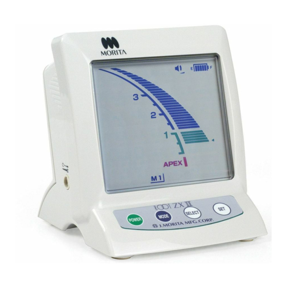
Page10 5. Operating the Unit Operation Panel Display and Switches Sound Volume Battery Power Indicator Canal Length Indicator Bar Off, Low, High This graph indicates remaining battery power. Replace the batteries when this indicator begins flashing. WARNING Never use the unit if the battery power indicator is flashing on and off. -
Page 13: Setting And Changing Memory
Page11 Setting and Changing Memory Use the Mode Switch to select M1, M2 or M3. Use the Select switch to select sound volume and Apical Line. Use the Set Switch to set the memory content. Press Mode to select the memory. Press Select to select the item. -
Page 14: Meter Display
Page12 Meter Display ■ The position of the file tip is shown by the canal length indicator bar on the display. The apical line flashes on and off once file is inserted into the root canal. NOTE Do not let the file touch the gums. This will cause the Flashes meter to jump to Apex. -
Page 15: Operating The Unit
Page13 Operating the Unit Corner of Mouth 1. Turn on the unit. Contrary 2. Hook the contrary electrode in the corner of the patient's Electrode mouth. WARNING Do not use an ultrasonic scaler with the contrary electrode attached to the patient. This is dangerous because electrical noise from the scaler could interfere with canal measurements and motor operation. - Page 16 Page14 NOTE Use files and reamers with plastic handles only. If the file has a metal handle, electrical leakage will occur when the handle is touched by fingers and it will prevent an accurate root canal measurement. Even if the file handle is made of plastic, make sure not to touch the metal part of the file with finger. ...
-
Page 17: Root Canals Not Suitable For Electronic Measurement Reading (Emr)
Page15 Root Canals not suitable for Electronic Measurement Reading (EMR) Accurate measurement cannot be obtained with the root canal conditions shown below. There may be other cases that an accurate measurement cannot be made. Root Canal with a large apical foramen Root canal that has an exceptionally large apical foramen due to a lesion or incomplete development cannot be accurately measured;... - Page 18 Page16 Crown or metal prosthesis touching gingival tissue Crown Accurate measurement cannot be obtained if the file touches a metal prosthesis that is touching gingival tissue. In this case, widen the opening at the top of the crown so that the file will not touch the metal prosthesis before taking a measurement.
-
Page 19: Emr And Radiography
Page17 EMR and Radiography Sometimes the EMR and the x-ray image do not correspond. This does not mean that the unit is not working properly or that the x-ray exposure is inaccurate. * Frequently, the actual apical foramen and anatomical apex do not correspond exactly. The actual apical foramen may be located towards the crown. -
Page 20: After Using The Unit
Page18 6. After Using the Unit 1. Turn off the unit. * The unit will automatically turn off after 10 minutes of non-use. 2. Disconnect the probe cord from the unit and remove the file holder and contrary electrode from the probe cord. - Page 21 Page19 Take out the old batteries and replace them with new ones. Make sure the plus and minus poles are correctly lined up. (1) Insert the batteries by first pressing center of the minus end against its spring contact and then sliding the plus end down into place.
-
Page 22: Sterilization And Replacement Parts
Replacement Parts * Replace parts as necessary depending on degree of wear and length of use. * Order replacement parts from your local dealer or J. MORITA regional office. Storage * Store the unit where it will not be exposed to x-rays or direct sunlight and where the ambient temperature range is between -10°C / 14°F and 70°C / 158°F ;... -
Page 23: Maintenance And Inspection
Page21 8. Maintenance and Inspection * The user (hospital, medical institute or clinic) is responsible for inspection and maintenance of the units.) Regular Inspection * This unit should be inspected every 6 months in accordance with the following maintenance and inspection items. -
Page 24: Troubleshooting
If the unit does not seem to be working properly, the user should first try to troubleshoot to solve operational problems. If the problems can not be solved after referring to the list below, contact your local dealer or J. MORITA regional office. Problem... -
Page 25: Replacement Parts List
A small file in a large root canal. Error Code There may be something wrong with the instrument if any of the following error codes appear. If any of these appear repeatedly, contact your local dealer or J. MORITA Office for repairs. Module Code*... -
Page 26: Technical Description
Page24 11. Technical Description Main unit and accessories Model DP-ZX-VL Type RCM-EX Classification Safety according to IEC 60601-1, IEC 60601-1-2, UL 60601-1, ISO 11498, ISO 7785-2, CAN/CSA C22.2 No.601.1-M90 European Directive 93/42/EEC IIa Canada Medical devices Class II Type of Protection Battery operated against Electric Shock Degree of Protection... - Page 27 ROOT ZX II may be repaired and serviced by the technicians of J. MORITA’s subsidiaries all over the world. technicians employed by authorized J. MORITA dealers and specially trained by J. MORITA. independent technicians specially trained and authorized by J. MORITA.
-
Page 28: Appendix- Electromagnetic Declaration
Page26 Appendix- Electromagnetic declaration Guidance and manufacturer’s declaration – electromagnetic emissions The DP-ZX-VL is intended for use in the electromagnetic environment specified below. The customer or the user of the DP-ZX-VL should assure that it is used in such an environment. Emissions test Compliance Electromagnetic environment - guidance... - Page 29 Page27 Guidance and manufacturer’s declaration – electromagnetic immunity The DP-ZX-VL is intended for use in the electromagnetic environment specified below. The customer or the user of the DP-ZX-VL should assure that it is used in such an environment. Electromagnetic environment - Immunity test IEC 60601 test level Compliance level...
- Page 30 Page28 Guidance and manufacturer’s declaration – electromagnetic immunity The DP-ZX-VL is intended for use in the electromagnetic environment specified below. The customer or the user of the DP-ZX-VL should assure that it is used in such an environment. IEC 60601 test Compliance Immunity test Electromagnetic environment - guidance...
- Page 31 Noise does not substantially change measurement. Accessory Probe Cord Code No.7503661 WARNING Use of the parts other than those accompanied or specified by J. MORITA MFG. CORP. may result in increased EMC emissions or decreased EMC immunity of the DP-ZX-VL. Operation 2012-09-21...
-
Page 32: Warranty
God. 8. J. MORITA MFG. CORP. will supply replacement parts and be able to repair the product for a period of 10 years after the manufacture of the product has been discontinued. - Page 36 2016.09. 2,000 ○ PUB. M8037-EA-6 Printed in Japan...
Need help?
Do you have a question about the ROOT ZX II and is the answer not in the manual?
Questions and answers