Table of Contents
Advertisement
Quick Links
SPAA 341 C /E351
Feeder Protection Relay
User´s manual and Technical description
I
n
I
n
f
n = 50Hz
I
n
U
60Hz
n
SPAA 341 C
80...265 V ~ –
18...80 V –
OPERATION INDICATORS
U1
SPCJ 4D28
SPCJ 4D28 /E
0
0
1
>
1
I
I
Start
2
>
2
I
I
Trip
3
>>
3
I
I
Start
4
>>
4
I
I
Trip
5
>>>
5
I
I
Start
6
>>>
6
I
I
Trip
7
>
7
I
I
Start
0
0
8
>
8
I
I
Trip
0
0
9
>>
9
I
I
Start
0
0
0
>>
0
I
I
Trip
0
0
∆
∆
11
>
11
I
Trip
A
A
CBFP
CBFP
RS 703 258 - AA
= 1A
5A ( ) I
2
=
1A
5A
(
I
)
0B
I
=
0,2A
1A
(
I
)
L1
5
0
=
100V
110V
120V
(
U
)
0
/E351
U
aux
U2
U3
SPCT 5D54
0
>
1
Start
Shot 1 due
>
2
Trip
Shot 2 due
>>
3
Start
Shot 3 due
>>
4
Trip
Shot 4 due
>>>
5
Start
Shot 5 due
>>>
6
Trip
Final trip
>
7
t
Start
d
>
8
t
Trip
r
>>
A
Start
CBFAIL
>>
Trip
>
I
Trip
Ser.No.
3 >
I
3 >
I
I
I
I
I
I
I
I
IRF
IRF
o
o
L2
L3
L1
L2
L3
RESET
RESET
I
/
I
I
/
I
>
>
n
n
STEP
STEP
[ ]
[ ]
t
>
s
t
>
s
k
k
I
>>
/
I
I
>>
/
I
n
n
>>
[ ]
>>
[ ]
t
s
t
s
I >>
>
/
I
I >>
>
/
I
n
n
[ ]
[ ]
t >>
>
s
t >>
>
s
>
/
I
>
/
I
I
I
0
n
0
n
[ ]
[ ]
t
>
s
t
>
s
0
0
k
k
0
0
I
>>
/
I
I
>>
/
I
0
n
0
n
>>
[ ]
>>
[ ]
t
s
t
s
0
0
∆
∆
>
[ ]
>
[ ]
I
%
I
%
∆
∆
t
>
[ ]
s
t
>
[ ]
s
PROGRAM
PROGRAM
SGF
SGF
SGB
SGB
SGR
SGR
TRIP
TRIP
SPCJ 4D28
SPCJ 4D28/E351
I
O
I
I
IRF
AR1
AR2
AR3
AR4
RESET
Shot 1
STEP
Shot 2
Shot 3
Shot 4
Shot 5
Final trip
t
r
t
d
PROGRAM
SGF
SGB
SGR
DEF
TRIP
SPCT 5D54
Advertisement
Chapters
Table of Contents

Related Manuals for ABB SPAA 341 C /E351

Summary of Contents for ABB SPAA 341 C /E351
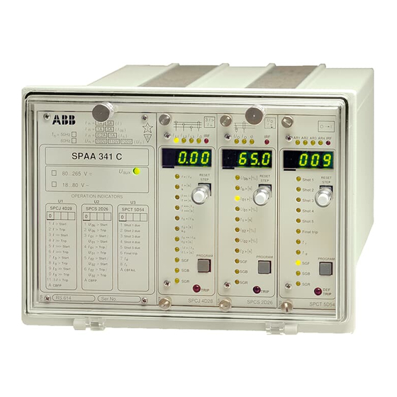
- Page 1 SPAA 341 C /E351 Feeder Protection Relay User´s manual and Technical description 3 > 3 > = 1A 5A ( ) I n = 50Hz 0,2A 60Hz 100V 110V 120V SPAA 341 C /E351 80...265 V ~ – RESET RESET...
-
Page 2: Table Of Contents
Ordering information ....................18 In addition to this general part the following descriptions of the individual modules are included in the complete manual of the feeder terminal relay SPAA 341 C /E351: Combined overcurrent and earth-fault relay module SPCJ 4D28... -
Page 3: Application
Seven freely configurable output relays and out- put relays for self-supervision and circuit breaker closing The feeder protection relay SPAA 341 C /E351 The integrated protection includes short-circuit Application is designed to be used for selective short-circuit and earth-fault protection for one feeder, auto- and earth-fault protection of radial networks. - Page 4 The feeder protection relay SPAA 341 C /E351 three-phase combined overcurrent and earth- Description of is a secondary relay system to be connected to fault relay modules type SPCJ 4D28 and type operation the current transformers of the network section SPCJ 4D28/E351 and an auto-reclose relay to be protected.
- Page 5 Auto-reclose relay The auto-reclose relay module SPCT 5D54 is indicator on the auto-reclose module is lit and module SPCT 5D54 capable of performing from one to five auto- information about which of the protection func- reclose shots and tripping the circuit breaker tions that initiated the unsuccessful AR se- finally.
-
Page 6: Connections
Connections 100/ 110/ 120 V 100/ 110/ 120 V 100/ 110/ 120 V 0.2 A SPA-ZC_ Fig. 1. Connection diagram for feeder protection relay SPAA 341 C /E351... - Page 7 16 15 14 13 12 11 10 9 Made in Finland = 63 Serial Port 6 7 8 9 10 11 12 13 14 15 16 CBPOS ARINH ARCTRL CBCS Fig. 2. Terminals of feeder protection relay SPAA 341 C /E351.
-
Page 8: Specification Of Input And Output Terminals
(5 A). Overcurrent protection 7—9 Phase current I (1 A). Overcurrent protection 13—14 Phase-to-phase voltage U (100 V). (Not used in SPAA 341 C /E351) 16—17 Phase-to-phase voltage U (100 V). (Not used in SPAA 341 C /E351) 37—38 Neutral current I (5 A). - Page 9 The circuit breaker closing can be implemented Note! Double-pole as one-pole or double-pole connection. At dou- When the CBCS relay is used with one-pole circuit breaker ble-pole circuit breaker operation the control connection the terminals 12 and 13 have to be control voltage is applied to both sides of the circuit connected together.
-
Page 10: Signal Flow Diagram
SGR6 SGB2 SGR5 SGB1 SGR4 SGR3 SGR2 SGR1 (U2) SPCJ 4D28/E351 SGR11 SGR10 SGR9 SGR8 SGR7 SGB3 SGR6 SGB2 SGR5 SGB1 SGR4 SGR3 SGR2 SGR1 SPCJ 4D28 (U1) Fig. 4. Internal signals of feeder protection relay SPAA 341 C /E351. -
Page 11: Operation Indicators
The I/O module of the feeder protection relay The output signals SS1...SS4, TS1...TS3 and I/O module SPAA 341 C /E351 is fitted in the rear part of CBCS control an output relay with the same the relay, in the same direction as the mother PC designation. -
Page 12: Power Supply Module
The power supply module forms the voltages The voltage range of the power supply module Power supply required for the relay modules and the auxiliary fitted in the relay is marked on the system panel module relay module. The power supply module is of the relay. - Page 13 Signalling contacts Terminal numbers X2/5-6, 7-8, 9-10-11 X2/12-13, 14-15-16 X2/1-2, 3-4 - rated voltage 250 V ac/dc - continuous current carrying capacity - make and carry for 0.5 s 10 A - make and carry for 3 s Breaking capacity for dc when the control circuit time constant L/R ≤40 ms at the control voltage levels - 220 V dc...
- Page 14 Data communication Transmission mode Fibre-optic serial bus Coding ASCII Data transfer rate, selectable 4800 Bd or 9600 Bd Electrical/optical bus connection module powered from the host relay - for plastic core cables SPA-ZC 21BB - for glass fibre cables SPA-ZC 21 MM Electrical/optical bus connection module powered from the host relay or from an external power source...
-
Page 15: Testing
The relay should be subject to regular tests in As the settings of the relay modules vary in Testing accordance with national regulations and in- different applications, these instructions present structions. The manufacturer recommends an the general features of the test procedure. Ordi- interval of five years between the tests. -
Page 16: Maintenance And Repair
Testing of auto- Testing of the auto-reclose relay module in- reclose relay module cludes: SPCT 5D54 - initiation of auto-reclosure - output relay operation - timers - alarm indication Testing of auto-reclose The operation of the auto-reclose module is Start the test by closing the circuit breaker and sequence recommended to be tested together with the wait for the possible reclaim time to elapse. - Page 17 40 mm, type SPA-ZX 302 connectors. 214 ±1 Panel cut-out Raising frame SPA-ZX 301 SPA-ZX 302 SPA-ZX 303 Fig. 15. Dimension and mounting drawings for feeder protection relay SPAA 341 C /E351.
-
Page 18: Order Numbers
I/O module. The female parts serial communication. Order data Example 1. Number and type designation 10 SPAA 341 C /E351 units 2. Order number RS 703 258 -AA/E351 3. Rated frequency = 50 Hz 4. Auxiliary voltage = 110 V dc 5. - Page 19 SPCJ 4D28 Overcurrent and earth-fault relay module User´s manual and Technical description 3 > RESET > STEP > >> >> I >> > t >> > > > >> >> ∆ > ∆ > PROGRAM TRIP SPCJ 4D28...
- Page 20 SPCJ 4D28 1MRS 750093-MUM EN Issued 95-05-04 Overcurrent and earth-fault Modified 99-10-04 Version D (replaces 34 SPCJ 18 EN1) relay module Checked TK Approved TK Data subject to change without notice Characteristics ........................ 2 Contents Description of function ....................3 Overcurrent unit .......................
-
Page 21: Overcurrent Unit
The overcurrent unit of the combined overcur- Note! At inverse time characteristic the effective Description of rent and earth-fault relay module SPCJ 4D28 is setting range of the low-set overcurrent stage is operation designed to be used for single-phase, two-phase 0.5…2.5 x I , although start current settings and three-phase overcurrent protection. - Page 22 Filter characteristics A low-pass filter suppresses the harmonics of the of the measuring phase currents and the earth-fault current meas- dB 10 inputs ured by the module. Figure 1 shows the signal suppression as a function of the frequency. f / f n Fig.
-
Page 23: Resetting
Auto-reclose start The start signals AR1, AR2 and AR3 can be to be activated by the desired start and operate initiation signals used as start initiation signals for the desired signals of the earth-fault module and the initia- autoreclose shots. The initiation signal AR2 can tion signal AR1 by the start and operate signals be programmed to be activated by the desired of both the overcurrent module and the earth-... - Page 24 Block diagram ∆I> t∆> SGF 5/1 Imax - Imin SGR 11 / x Imax RESET + SGF 4/1 PROGRAM SGR 1 / x SGF 5/2 50 ms I> t>, k SGR 2 / x SGF1/1…3 SGF 5/3 SGB 1/6 SGR 3 / x SGB 1/1 30 ms RESET +...
-
Page 25: Front Panel
Front panel 3 > Phase current and residual current indicators during current measurement and phase fault indicators at relay operation RESET Indicator for the start current of stage I> > STEP > Indicator for the operate time t> or time multiplier k Indicator for the start current of stage I>>... -
Page 26: Operation Indicators
Each protection stage has its own red start and started also operates the code number indicating Operation trip code shown as a number on the display. The starting turns into a code number indicating indicators TRIP indicator at the bottom right corner is operation. -
Page 27: Settings (Modified 99-10)
The setting values are indicated by the three to be set indicates the quantity currently being Settings rightmost digits on the display.The LED indi- displayed. cators adjacent to the symbols of the quantities Numerical settings (modified 99-10) Setting Explanation Setting range (factory default) I>/I Start current of stage I>... - Page 28 Switch settings Additional functions required for individual The tables below indicates the factory default applications are selected with switchgroups settings of the switches and the corresponding SGF1...8, SGB1...3 and SGR1...11. The switch checksums. The method for manual calculation numbers, 1...8, and the switch positions, 0 and of the checksum is shown at the end of this 1, are displayed when the switches are being set section.
- Page 29 Switch Function Factory default SGF2/1 Mode of operation of the start indicating code numbers of the differ- SGF2/2 ent stages. When the switches are in position 0, the start indication SGF2/3 code number automatically resets, once the fault disappears. When SGF2/4 the switch is in position 1, the code number remains lit, although the SGF2/5 fault disappears.
- Page 30 Switch Function Factory default SGF4/1 Selection of self-holding for output signal TS1 SGF4/2 Selection of self-holding for output signal TS2 SGF4/3 Selection of self-holding for output signal TS3 SGF4/4 Selection of self-holding for output signal TS4 When the switch is in position 0, the output signal returns to its initial state, when the measuring signal that caused operation falls below the set start level.
- Page 31 Switchgroups Using the different start and operation signals as point. The numbers of the different switches SGF6…8 autoreclose start initiation signals AR1, AR2 or and their weight factors are marked near the AR3. The signal selection possibilities are shown crossing points. The checksums for the different (modified 96-02) in Fig.
- Page 32 Switchgroups The functions of the control signals BS1, BS2 the switch is shown at the bottom row of the SGB1…3 and RRES (BS3) are defined with switchgroups matrix. By horizontally adding the weight fac- SGB1…3. The matrix shown below can be used tors of all the selected switches of a switchgroup as an aid for making the desired selections.
- Page 33 Switchgroups The start and operate signals of the protection point is marked with a switch number and the SGR1…11 stages are combined with the outputs SS1… corresponding weight factor of the switch is SS4 and TS1…TS4 with the switches of shown at the bottom row of the matrix.
-
Page 34: Measured Data
Manual checksum calculation Switch Weight factor Position Value SGF1/1 SGF1/2 SGF1/3 SGF1/4 SGF1/5 SGF1/6 SGF1/7 SGF1/8 Checksum of switchgroup SGF1 ∑ = The measured values are indicated by the three value currently presented is indicated by a yel- Measured data right-most digits on the display. - Page 35 The left-most digit of the display shows the isters is presented in the section "Main menus Recorded register address and the other three digits the and submenus of settings and registers". information recorded information. The structure of the reg- Register/ Recorded information STEP Current measured on phase L1, expressed as a multiple of the rated current I...
- Page 36 Register/ Recorded information STEP Duration of the latest start situation of stage I >, expressed as a percentage of the set operate time or, at IDMT mode of operation, of the calculated operate time. The register is updated each time the I >...
-
Page 37: Recorded Information
Register/ Recorded information STEP From register 0 it is possible to enter the TEST mode, in which the start and operate signals of the module can be activated one by one. The table below shows the activation order and the corresponding indicator lit when a signal is tested. Indicator Signal activated I>... -
Page 38: Menu Chart
Menu chart MAIN MENU SUBMENU STEP 0.5 s PROGRAM 1s Normal status, display off Value, that can be set in the Current in phase L1 setting mode Current in phase L2 REV. STEP 0.5 s FWD STEP 1 s Current in phase L3 SUBMENU Differential current ∆I Neutral current Io... - Page 39 The procedure for entering a submenu or a 1MRS 750066-MUM EN: "General charac- setting mode, setting a value and entering the teristics of D-type SPC relay modules". A short TEST mode is described in detail in the manual guide follows: Desired step Push-button Action...
- Page 40 IEC 255 standards and two curve groups, the RI >. See section "Setting switches". and the RXIDG curve groups are special type curve groups according to ABB praxis. The values of the constants α and β determine Characteristics The relay module incorporates four interna-...
- Page 41 RI-type The RI-type characteristic is a special character- where t = operate time in seconds characteristic istic that is principally used to obtain time k = time multiplier grading with mechanical relays. The character- I = phase current istic can be expressed by the mathematical ex- I>...
- Page 42 0.09 0.08 0.07 0.06 0.05 0.04 0.05 0.03 0.02 6 7 8 9 10 20 I/I> Fig. 8. Inverse-time characteristics of overcurrent and earth-fault relay module SPCJ 4D28 Extremely inverse...
- Page 43 0.09 0.08 0.07 0.06 0.05 0.05 0.04 0.03 0.02 6 7 8 9 10 20 I/I> Fig. 9. Inverse-time characteristics of overcurrent and earth-fault relay module SPCJ 4D28 Very inverse...
- Page 44 0.05 0.09 0.08 0.07 0.06 0.05 0.04 0.03 0.02 7 8 9 10 20 I/I> Fig. 10. Inverse-time characteristics of overcurrent and earth-fault relay module SPCJ 4D28 Normal inverse...
- Page 45 0.05 I/I> 7 8 9 Fig. 11. Inverse-time characteristics of overcurrent and earth-fault relay module SPCJ 4D28 Long-time inverse...
- Page 46 0.05 0.09 0.08 0.07 0.06 0.05 0.04 0.03 0.02 6 7 8 9 10 20 I/I> Fig. 12. Inverse-time characteristic of overcurrent and earth-fault relay module SPCJ 4D28 RI-type inverse...
- Page 47 0.09 0.08 0.07 0.06 0.05 0.04 0.4 0.5 0.05 0.03 0.02 7 8 9 10 I/I> Fig. 13. Inverse-time characteristic of overcurrent and earth-fault relay module SPCJ 4D28 RXIDG-type inverse...
-
Page 48: Technical Data
Feature Stage I> Stage I>> Stage I>>> Technical data Start current and ∞ and ∞ - at definite time 0.5…5.0 x I 0.5…40.0 x I 0.5…40.0 x I - at inverse time 0.5…2.5 x I Start time, typ. 70 ms 40 ms 40 ms Operate time at definite... -
Page 49: Serial Communication Parameters
The start and operate situations of the protec- to be communicated, is marked with a multi- Serial tion stages and the states of the output signals plier 1. The event mask is formed by the sum of communication are defined as events and provided with event the weight factors of all those events, that are to parameters codes, which can be transmitted to higher sys-... - Page 50 Code Event No. represent- Default ing the event value Output signal SS1 activated Output signal SS1 reset Output signal TS1 activated Output signal TS1 reset Output signal SS2 activated Output signal SS2 reset Output signal TS2 activated Output signal TS2 reset Default value of event mask V157 Output signal SS3 activated Output signal SS3 reset...
-
Page 51: Remote Transfer Data
Remote transfer data In addition to the event data all input data (I The password is also closed on loss of auxiliary data), setting values (S values), recorded infor- supply to the relay module. mation (V data) and certain other data of the overcurrent module can be read via the SPA bus. - Page 52 Outputs The state information indicates the state of a module. When the value = 0, the signal has not signal at a certain moment. The recorded func- been activated and when the value = 1, the signal tions indicate such activations of signals, that has been activated.
- Page 53 Setting values Variable Used Main Second Setting range settings setting setting (R, W, P) (R, W, P) Start current of stage I> 0.5…5.0 x I Operate time or 0.05…300 s time multiplier k of stage I> 0.05…1.0 Start current of stage I>> S3 *) 0.5…40 x I Operate time of stage I>>...
- Page 54 Measured and Measured value Para- Data Value recorded parameter meter direction values Last 15 min maximum demand current 0…2.5 x I Number of starts of stage I> 0…255 Number of starts of stage I>> 0…255 Number of starts of stage I >...
- Page 55 Control parameters Information Para- Data Value meter direction Resetting of operation indicators and V101 1 = reset perfomed latched output relay Resetting of indicators and latched output relay and clearing of registers V102 1 = reset perfomed Remote control of setting V150 0 = main settings enforced 1 = second settings...
- Page 56 Once the self-supervision system has detected number one (1) and a green code number that Fault codes an internal relay fault, the IRF indicator on the identifies the fault type. The fault codes should front panel of the relay module is lit. At the same be recorded and stated when service is ordered.
- Page 57 SPCJ 4D28/E351 Overcurrent and earth-fault relay module User´s manual and Technical description 3 > RESET > STEP > >> >> I >> > t >> > > > >> >> ∆ > ∆ > PROGRAM TRIP SPCJ 4D28/E351...
- Page 58 SPCJ 4D28/E351 1MRS 751890-MUM EN Issued 2000-07-20 Overcurrent and earth-fault Version A Checked relay module Approved Data subject to change without notice Characteristics ........................ 2 Contents Description of function ....................3 Overcurrent unit ....................... 3 Earth-fault unit......................3 Filter characteristics of the measuring inputa ............. 4 Phase discontinuity unit ....................
-
Page 59: Overcurrent Unit
The overcurrent unit of the combined overcur- Note! At inverse time characteristic the effective Description of rent and earth-fault relay module SPCJ 4D28/ setting range of the low-set overcurrent stage is operation E351 is designed to be used for single-phase, 0.5…2.5 x I , although start current settings two-phase and three-phase overcurrent protec-... - Page 60 Filter characteristics A low-pass filter suppresses the harmonics of the of the measuring phase currents and the earth-fault current meas- dB 10 inputs ured by the module. Figure 1 shows the signal suppression as a function of the frequency. f / f n Fig.
- Page 61 Auto-reclose start The start signals AR1, AR2 and AR3 can be to be activated by the desired start and operate initiation signals used as start initiation signals for the desired signals of the earth-fault module and the initia- autoreclose shots. The initiation signal AR2 can tion signal AR1 by the start and operate signals be programmed to be activated by the desired of both the overcurrent module and the earth-...
-
Page 62: Output Signals
Block diagram ∆I> t∆> SGF 5/1 Imax - Imin SGR 11 / x Imax RESET + SGF 4/1 PROGRAM SGR 1 / x SGF 5/2 50 ms I> t>, k SGR 2 / x SGF1/1…3 SGF 5/3 SGB 1/6 SGR 3 / x SGB 1/1 30 ms RESET +... -
Page 63: Front Panel
Front panel 3 > Phase current and residual current indicators during current measurement and phase fault indicators at relay operation Indicator for the start current of stage I> RESET > STEP Indicator for the operate time t> or time multiplier k >... -
Page 64: Operation Indicators
Each protection stage has its own red start and started also operates the code number indicating Operation trip code shown as a number on the display. The starting turns into a code number indicating indicators TRIP indicator at the bottom right corner is operation. -
Page 65: Settings
The setting values are indicated by the three to be set indicates the quantity currently being Settings rightmost digits on the display.The LED indi- displayed. cators adjacent to the symbols of the quantities Numerical settings Setting Explanation Setting range (factory default) I>/I Start current of stage I>... - Page 66 Switch settings Additional functions required for individual The tables below indicates the factory default applications are selected with switchgroups settings of the switches and the corresponding SGF1...8, SGB1...3 and SGR1...11. The switch checksums. The method for manual calculation numbers, 1...8, and the switch positions, 0 and of the checksum is shown at the end of this 1, are displayed when the switches are being set section.
- Page 67 Switch Function Factory default SGF2/1 Mode of operation of the start indicating code numbers of the differ- SGF2/2 ent stages. When the switches are in position 0, the start indication SGF2/3 code number automatically resets, once the fault disappears. When SGF2/4 the switch is in position 1, the code number remains lit, although the SGF2/5 fault disappears.
- Page 68 Switch Function Factory default SGF4/1 Selection of self-holding for output signal TS1 SGF4/2 Selection of self-holding for output signal TS2 SGF4/3 Selection of self-holding for output signal TS3 SGF4/4 Selection of self-holding for output signal TS4 When the switch is in position 0, the output signal returns to its initial state, when the measuring signal that caused operation falls below the set start level.
- Page 69 Switchgroups Using the different start and operation signals as point. The numbers of the different switches SGF6…8 autoreclose start initiation signals AR1, AR2 or and their weight factors are marked near the AR3. The signal selection possibilities are shown crossing points. The checksums for the different in Fig.
- Page 70 Switchgroups The functions of the control signals BS1, BS2 the switch is shown at the bottom row of the SGB1…3 and RRES (BS3) are defined with switchgroups matrix. By horizontally adding the weight fac- SGB1…3. The matrix shown below can be used tors of all the selected switches of a switchgroup as an aid for making the desired selections.
- Page 71 Switchgroups The start and operate signals of the protection point is marked with a switch number and the SGR1…11 stages are combined with the outputs SS1… corresponding weight factor of the switch is SS4 and TS1…TS4 with the switches of shown at the bottom row of the matrix.
-
Page 72: Measured Data
Manual checksum calculation Switch Weight factor Position Value SGF1/1 SGF1/2 SGF1/3 SGF1/4 SGF1/5 SGF1/6 SGF1/7 SGF1/8 Checksum of switchgroup SGF1 ∑ = The measured values are indicated by the three value currently presented is indicated by a yel- Measured data right-most digits on the display. - Page 73 The left-most digit of the display shows the isters is presented in the section "Main menus Recorded register address and the other three digits the and submenus of settings and registers". information recorded information. The structure of the reg- Register/ Recorded information STEP Current measured on phase L1, expressed as a multiple of the rated current I...
- Page 74 Register/ Recorded information STEP Duration of the latest start situation of stage I >, expressed as a percentage of the set operate time or, at IDMT mode of operation, of the calculated operate time. The register is updated each time the I >...
-
Page 75: Recorded Information
Register/ Recorded information STEP From register 0 it is possible to enter the TEST mode, in which the start and operate signals of the module can be activated one by one. The table below shows the activation order and the corresponding indicator lit when a signal is tested. Indicator Signal activated I>... -
Page 76: Menu Chart
Menu chart MAIN MENU SUBMENU STEP 0.5 s PROGRAM 1s Normal status, display off Value, that can be set in the Current in phase L1 setting mode Current in phase L2 REV. STEP 0.5 s FWD STEP 1 s Current in phase L3 SUBMENU Differential current ∆I Neutral current Io... - Page 77 The procedure for entering a submenu or a 1MRS 750066-MUM EN: "General charac- setting mode, setting a value and entering the teristics of D-type SPC relay modules". A short TEST mode is described in detail in the manual guide follows: Desired step Push-button Action...
- Page 78 IEC 255 standards and two curve groups, the RI >. See section "Setting switches". and the RXIDG curve groups are special type curve groups according to ABB praxis. The values of the constants α and β determine Characteristics The relay module incorporates four interna-...
- Page 79 RI-type The RI-type characteristic is a special character- where t = operate time in seconds characteristic istic that is principally used to obtain time k = time multiplier grading with mechanical relays. The character- I = phase current istic can be expressed by the mathematical ex- I>...
- Page 80 0.09 0.08 0.07 0.06 0.05 0.04 0.05 0.03 0.02 6 7 8 9 10 20 I/I> Fig. 8. Inverse-time characteristics of overcurrent and earth-fault relay module SPCJ 4D28/E351 Extremely inverse...
- Page 81 0.09 0.08 0.07 0.06 0.05 0.05 0.04 0.03 0.02 6 7 8 9 10 20 I/I> Fig. 9. Inverse-time characteristics of overcurrent and earth-fault relay module SPCJ 4D28/E351 Very inverse...
- Page 82 0.05 0.09 0.08 0.07 0.06 0.05 0.04 0.03 0.02 7 8 9 10 20 I/I> Fig. 10. Inverse-time characteristics of overcurrent and earth-fault relay module SPCJ 4D28/E351 Normal inverse...
- Page 83 0.05 I/I> 7 8 9 Fig. 11. Inverse-time characteristics of overcurrent and earth-fault relay module SPCJ 4D28/E351 Long-time inverse...
- Page 84 0.05 0.09 0.08 0.07 0.06 0.05 0.04 0.03 0.02 6 7 8 9 10 20 I/I> Fig. 12. Inverse-time characteristic of overcurrent and earth-fault relay module SPCJ 4D28/E351 RI-type inverse...
- Page 85 0.09 0.08 0.07 0.06 0.05 0.04 0.4 0.5 0.05 0.03 0.02 7 8 9 10 I/I> Fig. 13. Inverse-time characteristic of overcurrent and earth-fault relay module SPCJ 4D28/E351 RXIDG-type inverse...
-
Page 86: Technical Data
Feature Stage I> Stage I>> Stage I>>> Technical data Start current and ∞ and ∞ - at definite time 0.5…5.0 x I 0.5…40.0 x I 0.5…40.0 x I - at inverse time 0.5…2.5 x I Start time, typ. 70 ms 40 ms 40 ms Operate time at definite... -
Page 87: Serial Communication Parameters
The start and operate situations of the protec- to be communicated, is marked with a multi- Serial tion stages and the states of the output signals plier 1. The event mask is formed by the sum of communication are defined as events and provided with event the weight factors of all those events, that are to parameters codes, which can be transmitted to higher sys-... - Page 88 Code Event No. represent- Default ing the event value Output signal SS1 activated Output signal SS1 reset Output signal TS1 activated Output signal TS1 reset Output signal SS2 activated Output signal SS2 reset Output signal TS2 activated Output signal TS2 reset Default value of event mask V157 Output signal SS3 activated Output signal SS3 reset...
-
Page 89: Remote Transfer Data
Remote transfer data In addition to the event data all input data (I The password is also closed on loss of auxiliary data), setting values (S values), recorded infor- supply to the relay module. mation (V data) and certain other data of the overcurrent module can be read via the SPA bus. - Page 90 Outputs The state information indicates the state of a module. When the value = 0, the signal has not signal at a certain moment. The recorded func- been activated and when the value = 1, the signal tions indicate such activations of signals, that has been activated.
- Page 91 Setting values Variable Used Main Second Setting range settings setting setting (R, W, P) (R, W, P) Start current of stage I> 0.5…5.0 x I Operate time or 0.05…300 s time multiplier k of stage I> 0.05…1.0 Start current of stage I>> S3 *) 0.5…40 x I Operate time of stage I>>...
- Page 92 Measured and Measured value Para- Data Value recorded parameter meter direction values Last 15 min maximum demand current 0…2.5 x I Number of starts of stage I> 0…255 Number of starts of stage I>> 0…255 Number of starts of stage I >...
- Page 93 Control parameters Information Para- Data Value meter direction Resetting of operation indicators and V101 1 = reset perfomed latched output relay Resetting of indicators and latched output relay and clearing of registers V102 1 = reset perfomed Remote control of setting V150 0 = main settings enforced 1 = second settings...
- Page 94 Once the self-supervision system has detected number one (1) and a green code number that Fault codes an internal relay fault, the IRF indicator on the identifies the fault type. The fault codes should front panel of the relay module is lit. At the same be recorded and stated when service is ordered.
- Page 95 SPCT 5D54 Auto-reclose relay module User´s manual and Technical description RESET Shot 1 STEP Shot 2 Shot 3 Shot 4 Shot 5 Final trip PROGRAM TRIP SPCT 5D54...
-
Page 96: Contents Features
SPCT 5D54 1MRS 750095-MUM EN Issued 95-05-05 Auto-reclose relay module Modified 96-12-16 Version C (replaces 34 SPCT 7 EN1) Checked TK Approved TK Data subject to change without notice Features .......................... 2 Contents Application ........................3 Block schematic diagram (modified 96-12) ..............4 Description of operation .................... -
Page 97: Application
The majority (about 80-85%) of MV overhead auto-reclosures of desired type and duration, for Application line faults are transient and are automatically instance, one high-speed and one delayed auto- cleared by momentarily deenergizing the line. reclosure. When reclosing is initiatiated by start The rest of the faults (15-20%) can be cleared by of the protection, the auto-reclose module is longer interruptions. - Page 98 Block schematic diagram Shot 1 due autoreclose SGR1 sequences Shot 2 due SGR2 Shot 3 due SGR3 Shot 4 due SGR4 SGB2/6 Shot 5 due/tr due SGR5 SGB1...2/1 Def trip AR1 SGR6 ARSYNC SGB1...2/2 SGF3/1 Def trip AR2 SGR7 CINH SGB1...2/3 SGF3/2 Def trip AR3...
- Page 99 AR initiation signals Internal AR initiation line from protection relay modules Internal AR initiation line from protection relay modules Internal AR initiation line from protection relay modules AR initiation line via an external control input AR control signals CBPOS Circuit breaker position signal (energized = open) ARINH Signal for AR interruption and inhibition ARCTRL...
- Page 100 The operation of the auto-recloser is illustrated protection, a protective relay module trips the Description of in Figure 3. The shot pointer indicates the shot circuit breaker and initiate the AR shot simulta- operation to start when the auto-reclose module receives neously.
-
Page 101: Initiation Of Auto-Reclosing
Initiation of auto- The protective stages to initiate or block the AR 4) Should a start delay have been set for the AR reclosing functions are selected with SGF switches of the shot (rf. Auto-reclose shot initiated by a start protective relay modules. -
Page 102: Final Trip Function
Discriminating time When the circuit breaker is closed by the AR discriminating time t can be set out of use by and reclaim time shots 1...4, a discriminating time t will be selecting the value 0. ¨ started. Should one of the initiation signals AR1...AR4 be activated during the discriminat- The reclaim time is always started or restarted at ing time, the AR shot pointer moves to the value... -
Page 103: Interruption Of Auto-Reclosing
Interruption of An auto-reclose sequence (AR shots 1...5) can - the auto-reclose program is set out of use auto-reclosing be interrupted or is interrupted in the following - the auxiliary voltage supply to the relay is cases: interrupted or the internal self-supervision - the opening or closing of the circuit breaker system of the AR module detects a fault. -
Page 104: Ar Inhibition And Interruption Input Arinh
CBFAIL alarm The CBFAIL alarm is a 0.2 s pulse that is set pre-alarm level. A possible auto-reclose obtained when a CB operation fails or the sequence in progress is interrupted by unsuc- maintenance monitor reaches or falls below the cessful circuit breaker operation. -
Page 105: Front Panel
Front panel Device symbol Yellow indicators for Self-supervision indicator AR initiation Digital display RESET Shot 1 STEP Reset and display step Shot 2 push-button Shot 3 Shot 4 Operation indicators for Shot 5 settings Final trip PROGRAM Programming push-button Indicator for definite tripping TRIP Type designation of relay module SPCT 5D54... - Page 106 The auto-reclose module is provided with a The yellow LEDs above the digital display show Operation programmable DEF.TRIP operation indicator. the AR line that caused the operation. The indicators Normally, the operation indicator is lit, if the LEDs are reset by the initiation of a new shot or last AR shot selected is unsuccessful.
- Page 107 The settings of the module can be entered either on the front panel indicate the group of settings Settings via the push-buttons and the display on the or the setting value displayed at a given moment. front panel or over the serial communication Manual setting of the module is described in system.
- Page 108 Setting Description Setting range (Default value) Final trip Selection of operation mode for signals AR1...3: AR1 (the third digit from the right 0...1 AR2( the second digit from the right) 0...1 AR3 (the right-most digit) 0...1 (000) 0 = no final trip signal from the AR module (No) 1 = final trip signal from the AR module (Yes) Submenu 1: Selection of operation mode for signal AR4...
- Page 109 The switchgroups SGF1...4, SGB1...3 and are indicated on the display. These checksums Configuration SGR1...11 are used for selecting functions re- are found in the main menu of the relay module, switchgroups quired for different applications. The switch see "Main menu and submenu of settings and number, 1...8, and position, 0 or 1, are dis- registers".
- Page 110 Switchgroup SGF2 Switch Function Default SGF2/1 Synchrocheck for AR shot 1 SGF2/2 Synchrocheck for AR shot 2 SGF2/3 Synchrocheck for AR shot 3 SGF2/4 Synchrocheck for AR shot 4 SGF2/5 Synchrocheck for AR shot 5 When the switch = 0, no synchrocheck function is available When the switch = 1, the ARSYNC signal has to be active before the circuit breaker is closed (waiting time max.
- Page 111 Switchgroups The switchgroups SGB1...3 are used to con- switches of each switchgroup gives the switch- SGB1...3 figure the control signals ARCTRL, BS2 and group checksums to the right of the matrix. RRES. The matrix below can be used for the Switches not mentioned are not used and should configuration.
- Page 112 Switchgroups The switchgroups SGR1...11 are used to weighting values of the switches selected from SGR1...SGR11 configure the output signals of the module to each switchgroup the checksums of the operate as desired output signals SS1...SS4 or switchgroups are obtained to the right of the TS1...TS3.
-
Page 113: Recorded Data
The red digit on the display indicates the address Recorded data code of the register and the other three digits the value of the register. Register/ Recorded information STEP Total number of AR shots 1 (0...999). Register 3 includes four subregisters with the following contents: Total number of AR shots 1 (0...255), initiated by 1) signal AR1... - Page 114 Register/ Recorded information STEP Total number of DEF.TRIP alarm signals (0...999). Register 8 includes four subregisters with the following contents: Total number of DEF.TRIP alarm signals (0...255), initiated by 1) signal AR1 2) signal AR2 3) signal AR3 4) signal AR4 The main register contains information about the number of AR shots (0...5) carried out during the latest AR sequence.
- Page 115 Register/ Recorded information STEP From this register it is possible to enter the TEST mode, in which the output signals of the relay module can be activated one by one. The setting operation indicators and their corresponding output signals are presented below. Note! The CB closing signal can also be activated in the TEST mode.When all setting indicators are flashing, the CBCS signal can be activated by pressing the push-...
-
Page 116: Main Menu And Submenus For Settings And Registers
Main menu and submenus for MAIN MENU SUBMENUS settings and STEP 0.5 s PROGRAM 1s registers REV. STEP 0.5 s FWD. STEP 1 s Normal status, display off Select shot 1 function Select shot 1 Dead time shot 1 by AR1, AR2 and AR3 function by AR4 Select shot 2 function Select shot 2... - Page 117 Submenus are indicated by blinking numbers The value can be changed in setting mode Start delay Start delay Start delay Start delay time for AR1 time for AR2 time for AR3 time for AR4 Start delay Start delay Start delay Start delay time for AR1 time for AR2...
-
Page 118: Technical Data
Maximum number of successive AR shots Technical data during a sequence Start delay 0.00...10.0 s Dead time 0.20...300 s Discriminating time 0.00...30.0 s Reclaim time 0.20...300 s Final trip time 0.00...5.00 s CB closing impulse 0.10...2.00 s CB opening impulse 0.10...2.00 s ±1% of setting value or ±30 ms Operate time accuracy... - Page 119 Channel Code Event Weighting Default coefficient Circuit breaker events Change in CB position: 1 -> 0 (open) Change in CB position: 0 -> 1 (closed) Manual CB opening Manual CB closing OPEN output activated OPEN output reset CLOSE output activated CLOSE output reset Event mask V156 = 15...
- Page 120 Channel Code Event Weighting Default coefficient Events for AR shot 2 AR shot 2 started AR shot 2 initiated via AR1 AR shot 2 initiated via AR2 AR shot 2 initiated via AR3 AR shot 2 initiated via AR4 AR shot 2 concluded AR shot 2 successful Event mask 2V155 = 1...
-
Page 121: Data To Be Transferred Over The Serial Bus (Modified 96-12)
Channel Code Event Weighting Default coefficient Events for DEF.TRIP alarm DEF.TRIP alarm activated DEF.TRIP alarm activated by AR1 DEF.TRIP alarm activated by AR2 DEF.TRIP alarm activated by AR3 DEF.TRIP alarm activated by AR4 DEF.TRIP alarm reset Event mask 7V155 = 33 In addition to the event codes input data (I data), closing the password. - Page 122 Data Channel Code Data Value direction Status data of output signals Signal AR shot 1 due 0 = not active 1 = active Signal AR shot 2 due 0 = not active 1 = active Signal AR shot 3 due 0 = not active 1 = active Signal AR shot 4 due...
- Page 123 Data Channel Code Data Value direction Setting parameters Setting values for AR shot 1 on channel 1, for AR shot 2 on channel 2, etc. Dead time, AR shots 1...5 1...5 R,W,(P) 0.2...300 s Initiated by signal AR1 1...5 R,W,(P) 0 = no operation 1 = AR shot initiated 2 = initiation of AR shot...
- Page 124 Data Channel Code Data Value direction General setting values on channel 0 Reclaim time t R,W,(P) 0.2...300 s Checksum ∑ - switchgroup SGF1 R,W,(P) 0...255 - switchgroup SGF2 R,W,(P) 0...255 - switchgroup SGF3 R,W,(P) 0...255 - switchgroup SGB1 R,W,(P) 0...255 - switchgroup SGB2 R,W,(P) 0...255...
- Page 125 Data Channel Code Data Value direction Recorded values Values recorded for AR shot 1 on channel 1, values recorded for AR shot 2 on channel 2, etc. Total number of AR shots 1...5 0...999 Number of AR shots initiated by - signal AR1 1...5 R,W,(P)
- Page 126 Data Channel Code Data Value direction Event mask - for AR shot 1 V155 0...127 - for AR shot 2 V155 0...127 - for AR shot 3 V155 0...127 - for AR shot 4 V155 0...127 - for AR shot 5 V155 0..127 - for final trip...
-
Page 127: Trouble Shooting
Trouble-shooting Circuit breaker open CB opening failed. No information about change of CB position (closed -> open) was received during Indication the opening impulse (S29) and, consequently, on display the AR sequence was interrupted. However, the circuit breaker was opened. CB closing failed. - Page 128 Auto-reclosing does not start Reclaim time tr running. Indication - the ARINH input for inhibiting and interrupting on display auto-reclosing is energized Indication Circuit breaker maintenance monitor zero on display (inhibiting function) Indication One of the initiation signals AR1...4 continuously on display active Circuit...
-
Page 129: Definitions
Reclosure Final trip (used when reclosing is initiated by Definitions Operation, whereby the circuit breaker is auto- the start of the proteciton) matically closed after a preset time delay from This facility provides a faster trip from the AR circuit breaker opening initiated by the protec- module when the last shot in the sequence tion relay. - Page 131 General characteristics of D-type relay modules User´s manual and Technical description 3 > Relay symbol Fastening screw Self-supervision alarm indicator Indicators for measured (Internal Relay Fault) quantities Display, 1 + 3 digits RESET > STEP t [ ] > Reset / Step push-button >>...
- Page 132 1MRS 750066-MUM EN General characteristics Issued 95-04-12 of D type relay modules Version A (replaces 34 SPC 3 EN1) Checked JH Approved TK Data subject to change without notice Front panel lay-out ......................1 Contents Control push buttons ..................... 3 Display ...........................
-
Page 133: Display
The front panel of the relay module contains certain position in the main menu to the corre- Control two push buttons. The RESET / STEP push sponding submenu, for entering the setting push-buttons button is used for resetting operation indicators mode of a certain parameter and together with and for stepping forward or backward in the the STEP push button for storing the set values. -
Page 134: Settings
Part of the settings and the selections of the Selector switch- operation characteristic of the relay modules in Switch No Pos. Weigth Value groups SGF, SGB various applications are made with the selector and SGR switchgroups SG_ . The switchgroups are soft- ware based and thus not physically to be found in the hardware of the relay module. -
Page 135: Setting Mode
NOTE! During any local man-machine com- any doubt about the settings of the module to be munication over the push buttons and the dis- inserted, the setting values should be read using play on the front panel a five minute time-out a spare relay unit or with the relay trip circuits function is active. - Page 136 MAIN MENU SUBMENUS STEP 0.5 s PROGRAM 1 s Normal status, display off Current on phase L1 Current on phase L2 Current on phase L3 REV. STEP 0.5 s FWD. STEP 1 s Neutral current Io SUBMENUS Second setting Main setting Actual start value I>...
- Page 137 Example 1 Operation in the setting mode. Manual setting for the main setting is 0.80 x I and for the of the main setting of the start current value I> second setting 1.00 x I . The desired main start of an overcurrent relay module.
- Page 138 RESET STEP Set the digit with the STEP push button. 1 1. 0 5 PROGRAM Press the PROGRAM push button to make the decimal point flash. 1 1. 0 5 RESET STEP If needed, move the decimal point with the STEP push button.
- Page 139 Example 2 Operation in the setting mode. Manual setting SGF1/1and SGF1/3 are to be set in position 1. of the main setting of the checksum for the This means that a checksum of 005 should be switchgroup SGF1 of a relay module. The initial the final result.
- Page 140 RESET STEP The switch position is altered to the desired position 1 by pressing the STEP push button once. PROGRAM Using the same procedure the switches SGF 1/ 5 x 1 s 4...8 are called up and, according to the exam- ple, left in position 0.
- Page 141 The parameter values measured at the moment Submenu 2 of register A contains a bus commu- Recorded when a fault occurs or at the trip instant are nication monitor for the SPAbus. If the protec- information recorded in the registers. The recorded data, tion relay, which contains the relay module, is except for some parameters, are set to zero by linked to a system including a contol data...
-
Page 142: Trip Test Function
Register 0 also provides access to a trip test The selected starting or tripping is activated by Trip test function function, which allows the output signals of the simultaneous pressing of the push buttons relay module to be activated one by one. If the STEP and PROGRAM. - Page 143 Example 3 Trip test function. Forced activation of the outputs. Step forward on the display to register 0. RESET STEP n x 1 s 0 0 0 0 Press the PROGRAM push button for about 3 > five seconds until the three green digits to the right.
-
Page 144: Second Settings
To proceed to the next position press the PRO- 3 > GRAM push button for about 1 second until the indicator of the second setting starts flash- 0 0 0 0 ing. RESET > STEP PROGRAM t [ ] > >>... -
Page 145: Fault Codes
A relay module is provided with a multiple of indicator is reset by means of the RESET push Operation separate operation stages, each with its own button of the relay module. An unreset opera- indication operation indicator shown on the display and a tion indicator does not affect the function of the common trip indicator on the lower part of the protection relay module. - Page 146 ABB Oy Substation Automation P.O.Box 699 FIN-65101 VAASA Finland Tel. +358 (0)10 22 11 Fax.+358 (0)10 22 41094 www.abb.com/substationautomation...