Table of Contents
Advertisement
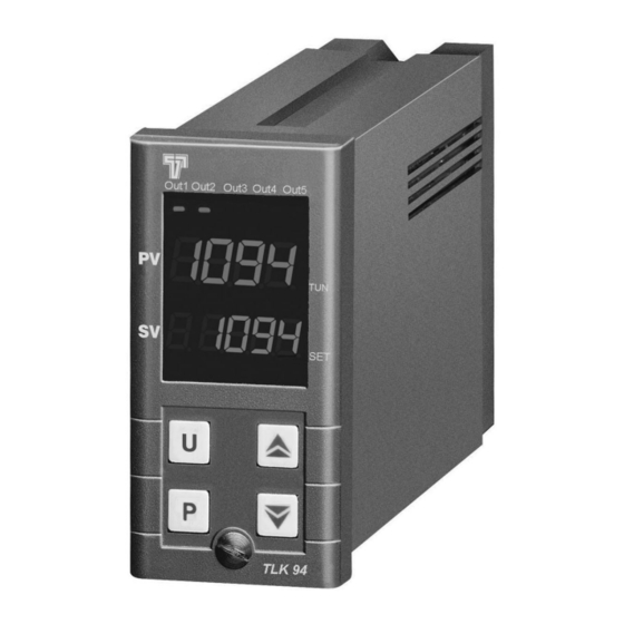
TLK 94
MICROPROCESSOR-BASED
DIGITAL
ELECTRONIC CONTROLLER
OPERATING INSTRUCTIONS
Vr. 01 (ENG) - 01/10
cod.: ISTR-MTLK94ENG1
TECNOLOGIC S.p.A.
VIA INDIPENDENZA 56
27029 VIGEVANO (PV) ITALY
TEL.: +39 0381 69871
FAX: +39 0381 698730
internet : http:\\www.tecnologic.it
e-mail: info@tecnologic.it
FOREWORD
This
manual
necessary for the product to be installed
correctly
maintenance and use; we therefore recommend
that the utmost attention is paid to the following
instructions and to save it.
This document is the exclusive property of TECNOLOGIC
S.p.A. which forbids any reproduction and divulgation , even
in part, of the document, unless expressly authorized.
TECNOLOGIC S.p.A. reserves the right to make any formal or
functional changes at any moment and without any notice.
Whenever a failure or a malfunction of the device may cause
dangerous situations for persons, thing or animals, please
remember that the plant has to be equipped with additional
devices which will guarantee safety.
Tecnologic S.p.A. and its legal representatives do not assume
any responsibility for any damage to people, things or animals
deriving from violation, wrong or improper use or in any case
not in compliance with the instrument's features .
TECNOLOGIC spa - TLK 94 -OPERATING INSTRUCTIONS - Vr.01 - 01/10 - ISTR-MTLK94ENG1 - PAG. 1
contains
the
and
also
instructions
INDEX
1
INSTRUMENT DESCRIPTION
1.1
GENERAL DESCRIPTION
1.2
FRONT PANEL DESCRIPTION
2
PROGRAMMING
2.1
FAST PROGRAMMING OF THE SET POINT
2.2
SELECTION OF CONTROL STATE AND PARAMETERS
PROGRAMMING
2.3
PARAMETER PROGRAMMING LEVELS
2.4
CONTROL STATES
2.5
ACTIVE SET POINT SELECTION
3
INFORMATION ON INSTALLATION AND USE
3.1
PERMITTED USE
3.2
MECHANICAL MOUNTING
3.3
ELECTRICAL CONNECTIONS
3.4
ELECTRICAL WIRING DIAGRAM
4
FUNCTIONS
4.1
MEASURING AND VISUALIZATION
4.2
OUTPUT CONFIGURATION
4.3
ON/OFF CONTROL
4.4
NEUTRAL ZONE ON/OFF CONTROL
4.5
SINGLE ACTION PID CONTROL
4.6
DOUBLE ACTION PID CONTROL
4.7
PID CONTROL FOR MOTORIZED ACTUATORS WITH
TIME POSITIONING
4.8
AUTO-TUNING AND SELF-TUNING FUNCTIONS
4.9
CONTROL POWER LIMITATION
4.10
LIMITATION OF THE CONTROL POWER VARIATION
SPEED (MAXIMUM RATE OF RISE)
4.11
SPLIT RANGE FUNCTION
4.12
REACHING OF SET POINT AT CONTROLLED SPEED
AND AUTOMATIC COMMUTATION BETWEEN TWO
SET POINTS
4.13
SOFT-START FUNCTION
4.14
ALARMS OUTPUTS FUNCTIONS
4.15
HEATER BREAK ALARM FUNCTION
4.16
LOOP BREAK ALARM FUNCTION
4.17
FUNCTION OF KEY "U"
4.18
DIGITAL INPUTS
4.19
RS 485 SERIAL INTERFACE
4.20
PARAMETERS CONFIGURATION BY A01
5
PROGRAMMABLE PARAMETERS TABLE
6
PROBLEMS , MAINTENANCE AND GUARANTEE
6.1
ERROR WARNINGS
6.2
CLEANING
6.3
GUARANTEE AND REPAIRS
7
TECHNICAL DATA
7.1
ELECTRICAL DATA
7.2
MECHANICAL DATA
7.3
MECHANICAL DIMENSIONS, PANEL CUT-OUT AND
MOUNTING
7.4
FUNCTIONAL DATA
7.5
MEASURING RANGE TABLE
7.6
INSTRUMENT ORDERING CODES
information
1 - INSTRUMENT DESCRIPTION
for
its
1.1 - GENERAL DESCRIPTION
TLK 94 is a "single loop" digital microprocessor-based controller,
with ON/OFF, Neutral Zone ON/OFF, PID single action, PID dual
action (direct and reverse) control, PID for motorized actuators with
time positioning control. The instrument is equipped with
AUTO-TUNING
SELF-TUNING function and automatic calculation of the FUZZY
OVERSHOOT CONTROL parameter for PID control. The PID
control has a particular algorithm with TWO DEGREES OF
FREEDOM that optimises the instrument's features independently
of the event of process disturbances and Set Point variations.
Furthermore,
communication using MODBUS-RTU communication protocol and
a transmission speed up to 38.400 baud. The process value is
visualized on 4 red displays, the Set value is visualized on 4 green
displays while the outputs status is indicated by 6 leds. The
function
(FAST
or
the
instrument
allows
OSCILLATING
type),
for
RS485
serial
Advertisement
Table of Contents

Related Manuals for Tecnologic TLK 94


Summary of Contents for Tecnologic TLK 94
- Page 1 4 red displays, the Set value is visualized on 4 green not in compliance with the instrument’s features . displays while the outputs status is indicated by 6 leds. The TECNOLOGIC spa - TLK 94 -OPERATING INSTRUCTIONS - Vr.01 - 01/10 - ISTR-MTLK94ENG1 - PAG. 1...
-
Page 2: Front Panel Description
“diSP”, to visualize other values. Set Point parameters but it can contain all the desired parameters (see par. 2.3). TECNOLOGIC spa - TLK 94 -OPERATING INSTRUCTIONS - Vr.01 - 01/10 - ISTR-MTLK94ENG1 - PAG. 2... -
Page 3: Parameters Programming Levels
“SPLL” and the one programmed on par. in par. “Edit” (contained in the group “ PAn “). “SPHL”. This parameter can be programmed as : TECNOLOGIC spa - TLK 94 -OPERATING INSTRUCTIONS - Vr.01 - 01/10 - ISTR-MTLK94ENG1 - PAG. 3... -
Page 4: Information On Installation And Use
The instrument allows for measuring calibration, which may be cause damage to people, things or animals. used to recalibrate the instrument according to application needs, by using par. “OFSt” and “rot”. TECNOLOGIC spa - TLK 94 -OPERATING INSTRUCTIONS - Vr.01 - 01/10 - ISTR-MTLK94ENG1 - PAG. 4... -
Page 5: Output Configuration
(“ AL1, 2, 3, ("Func”=CooL), it deactivates the output, when the process value TECNOLOGIC spa - TLK 94 -OPERATING INSTRUCTIONS - Vr.01 - 01/10 - ISTR-MTLK94ENG1 - PAG. 5... -
Page 6: Neutral Zone On/Off Control
The PID type control for motorised actuators therefore acts on the following parameters : outputs 1.rEG and 2.rEG depending on the active Set point “SP” "Pb" - Proportional Band TECNOLOGIC spa - TLK 94 -OPERATING INSTRUCTIONS - Vr.01 - 01/10 - ISTR-MTLK94ENG1 - PAG. 6... - Page 7 "Prat" - Ratio P 2.rEG/ P 1.rEG higher process value is not found the display will show “ErAt” and To activate the AUTO-TUNING function proceed as follows : TECNOLOGIC spa - TLK 94 -OPERATING INSTRUCTIONS - Vr.01 - 01/10 - ISTR-MTLK94ENG1 - PAG. 7...
-
Page 8: Control Power Limitation
(and therefore with “dEr” expressed in [% / sec]. and “Int” = OFF) with “Prat” = 1.0 and “rS” = 0.0 was considered. TECNOLOGIC spa - TLK 94 -OPERATING INSTRUCTIONS - Vr.01 - 01/10 - ISTR-MTLK94ENG1 - PAG. 8... -
Page 9: Soft-Start Function
(ex. for certain heating elements). The function depends on the following parameters : “St.P” - Soft-Start power LoAb HiAb TECNOLOGIC spa - TLK 94 -OPERATING INSTRUCTIONS - Vr.01 - 01/10 - ISTR-MTLK94ENG1 - PAG. 9... -
Page 10: Heater Break Alarm Function
+2 = ALARM DELAYED: When the alarm condition occurs, delay groups “ Out”, programming the parameter as : counting begins, as programmed on par. “AL1d” (expressed in TECNOLOGIC spa - TLK 94 -OPERATING INSTRUCTIONS - Vr.01 - 01/10 - ISTR-MTLK94ENG1 - PAG. 10... -
Page 11: Digital Input
“OPE” (programmable in software protocol adopted for TLK94 is a MODBUS RTU type, the group “ InP”) . TECNOLOGIC spa - TLK 94 -OPERATING INSTRUCTIONS - Vr.01 - 01/10 - ISTR-MTLK94ENG1 - PAG. 11... -
Page 12: Parameters Configuration By " A01"
Ptc= PTC KTY81-121 ntc= NTC 103-AT2 0.20= 0..20 mA 4.20= 4..20 mA 0.1= 0..1 V 0.5=0..5 V 1.5= 1..5 V 0.10= 0..10 V 2.10= 2..10 V TECNOLOGIC spa - TLK 94 -OPERATING INSTRUCTIONS - Vr.01 - 01/10 - ISTR-MTLK94ENG1 - PAG. 12... - Page 13 AL2 for high see “O1F” On / OFF or low alarm Beginning of output 2 0 / no_0 Aor2 scale if analogical type TECNOLOGIC spa - TLK 94 -OPERATING INSTRUCTIONS - Vr.01 - 01/10 - ISTR-MTLK94ENG1 - PAG. 13...
- Page 14 / min. Minimum power 0 ÷ ro1.H Output where alarm HB Out1 / Out2 ro1.L is addressed Out3 / Out4 / output from 1.rEG TECNOLOGIC spa - TLK 94 -OPERATING INSTRUCTIONS - Vr.01 - 01/10 - ISTR-MTLK94ENG1 - PAG. 14...
-
Page 15: Cleaning
AC3 / 250 VAC), OUT2,3,4,5:SPST-NO (4 A-AC1, 2 A-AC3 / 250 LoCL = No (Local only) VAC),or in tension to drive SSR (12 VDC / 20 mA). TECNOLOGIC spa - TLK 94 -OPERATING INSTRUCTIONS - Vr.01 - 01/10 - ISTR-MTLK94ENG1 - PAG. 15... -
Page 16: Mechanical Data
IRS range “A” -46 ... 785 °C -46.0 ... 785.0 °C “HCFG” = tc -50 ... 1445 °F -50.8 ... 999.9 °F “SEnS”= Ir.J - Ir.CA TECNOLOGIC spa - TLK 94 -OPERATING INSTRUCTIONS - Vr.01 - 01/10 - ISTR-MTLK94ENG1 - PAG. 16... -
Page 17: Instrument Ordering Code
O = OUT3 VDC for SSR - = (No OUT3) e : OUTPUT OUT4 R = OUT4 Relay O = OUT4 VDC for SSR TECNOLOGIC spa - TLK 94 -OPERATING INSTRUCTIONS - Vr.01 - 01/10 - ISTR-MTLK94ENG1 - PAG. 17...
Need help?
Do you have a question about the TLK 94 and is the answer not in the manual?
Questions and answers