Table of Contents
Advertisement
Advertisement
Table of Contents

Related Manuals for CRT MICRON U/V


Summary of Contents for CRT MICRON U/V
- Page 2 User Manual Dual band transceiver 430-440 MHz RX/TX 144-146 MHz RX/TX...
- Page 3 Storage : Classe 1 -30/85% (° Humidity) Transport :- 30/85% (° Humidity ) operating temperature –30 à + 50° Using cycle TX 10%/RX 90% The CRT MICRON UV HAM was approved in the followed countries that implement the CEPT regulation TR 61/01 AT,BE,BG,CH,CY,CZ,DE,DK,EE,FI,FR,GR,HR,HU,IE,IS,IT,LI,LT,LU,LV,MT,NL,NO,PL,PT,RO,SE,SI,SK,UK. ES...
-
Page 6: Table Of Contents
CONTENTS 1.FUNCTIONS & FEATURES ................1 2.ACCESSORIES ..................... 2 3.INITIAL INSTALLATION ................3 4.GETTING ACQUAINTED ................8 5.WORKING MODE ..................11 6.BASIC OPERATIONS .................. 12 7.FUNCTION MENU ..................11 8.CHANNEL MENU ..................20 9.KEYPAD MENU SETUP ................23 10.PROGRAMMING SOFTWARE ..............24 11.MAINTENANCE .................. -
Page 7: Functions & Features
1. FUNCTIONS & FEATURES CRT MICRON Mobile Radio has nice housing, stoutness & stability, advanced and reliable functions, perfect & valuable. This amateur mobile radio especially designs for drivers and it pursues philosophy of innovation and practicality. More functions as follows: ♦... -
Page 8: Accessories
2. ACCESSORIES 2.1 Standard Accessories FUNC DC Power Cable Microphone Transceiver with Fuse Holder Mobile Bracket manual Adjusting screws Fuse(10A 250V) 2.2 Optional Accessories PC cable External Speaker Regulated Power Supply Programming Software Car Antenna... -
Page 9: Initial Installation
3. INITIAL INSTALLATION 3.1 Mobile Installation To install the transceiver, select a safe, convenient location inside your vehicle that minimizes danger to your passengers and yourself while the vehicle is in motion. Consider installing the unit at an appropriate position so that knees or legs will not strike it during sudden braking of your vehicle. - Page 10 1.Route the DC power cable supplied with the transceiver directly to the vehicle's battery terminals using the shortest path from the transceiver. ♦ We recommend you do not use the cigarette lighter socket as some cigarette lighter sockets introduce an unacceptable voltage drop. ♦...
- Page 11 Regulated power supply (QRP-01) Black Regulated power supply (QRP-01) DC power cable with fuse holder (QPL-01) 2.Connect the transceiver's DC power connector to the connector on the DC power cable. ♦ Press the connectors firmly together until the locking tab clicks. »...
-
Page 12: Antenna Connection
If you plan to use an external speaker, choose a speaker with an impedance of 8Ω. The external speaker jack accepts a 3.5mm (1/8") mono (2-conductor) plug. CRT MS 120E » External speaker adopt double port BTL, please care about the connecting way. - Page 13 Error CRT MS 120E Ground 3.4.2 Microphone For voice communications, connect a microphone equipped with an 8-pin modular plug into the modular socket on the front of the main unit. Press irmly on the plug until the locking tab clicks.
-
Page 14: Getting Acquainted
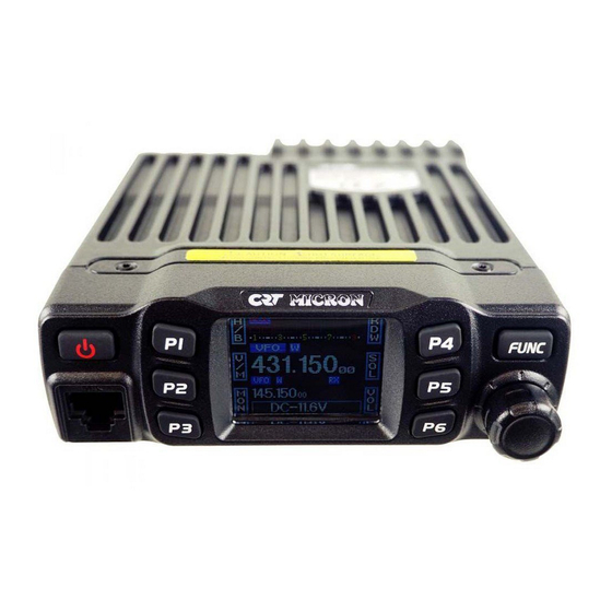
4. GETTING ACQUAINTED 4.1 Front panel FUNC Functions Power On/Off/Mute Self define key Self define key Self define key Self define key Self define key Self define key Function key/ function group key Microphone Jack Channel switch/Push button/Key lock LCD display Display channel/frequency/function setting 4.2 Rear panel EXT SP... - Page 15 Functions Antenna connector Connect a 50 ohm antenna Ex-Speaker Jack Connect optional SP-01 external speaker Power cable Connect a standard DC power cable 4.3 Display 11 12 13 14 18 19 20 21 22 Functions Displays the self define function when press P1 Displays the self define function when press P2 Displays the self define function when press P3 Displays the self define function when press P4...
- Page 16 4.4 Microphone Functions Increase frequency, channel number or setting value DOWN Decrease frequency, channel number or setting value Press the PTT (Push-TO-Talk) key to transmit Number Key Input VFO frequency or DTMF dial out etc. A/B band Choose left band or right band as Main band Band indicator The indicator light on for Main band TX/RX indicator...
-
Page 17: Working Mode
5. WORKING MODE (AMATEUR TRANSCEIVER OR CHANNEL MODE TRANSCEIVER) According to practical application, you can set the radio works as Amateur Transceiver mode or Channel Transceiver mode. There are also 2 levels operation menu to set functions as you need. It is easy and convenient. FUNC MENU is for set background function, CHAN MENU for set channel function, MINI KEY menu for set self define key, HAND KEY for set self mic define key. -
Page 18: Basic Operations
6. BASIC OPERATIONS 6.1 Switching the Power On/Off 1. Power On: in power off state press , the LCD displays "WELCOME" then will displays current frequency or channel. 2. Power Off: in power on state, press for 2 seconds, the LCD displays "CLOSING", then the LCD display disappears. -
Page 19: Switch Between Vfo And Channel Mode
6.5 Receiving When the channel you are operating being called, the screen shows red RX and field strength in this way you can hear the calling. » When the RX icon and field strength flashes, but can not hear the calling, it means current channel receive a matching carrier but unmatching signaling. -
Page 20: Channel Delete
6.10 Channel Delete 1. In channel mode, turn the channel knob or microphone [UP]/[DOWN] key to choose an unwanted channel. 2. Short press [FUNC] key to switch function group, choose the [PX] key defined as V/ M function, press this key together with [FUNC] key for 2 seconds, current channel is deleted and automatical jump to next channel. -
Page 21: Keypad Lockout
6.14 Frequency/Channel Scan Frequency Scan In frequency (VFO) mode, this function is designed to monitor signal of all frequency points under each step size. 1. In VFO mode, short press [FUNC] key to switch function group, choose the [PX] key defined as SCN function. -
Page 22: Function Menu
7. FUNCTION MENU 1. Hold [FUNC] key to enter SELECT MENU interface. 2. Short press [P4], [P6] key or turn channel knob to choose menu list. Short press [P5] can fast turn page. 3. Press [PUSH] button to enter FUNC MENU setting. 4. -
Page 23: Scan Dwell Time Setup
7.5 Volume level setting 1. Enter FUNCTION MENU list, choose No.05 function 2. Press [PUSH] button, the menu value in LCD turns to green color. 3. Turn channel knob to choose wanted setting 1-36: total 36 levels available 4. Press [PUSH] button or [P3] key to store setting and exit 7.6 Password setting After enable this function, must be input correct password then can turn on the transceiver. -
Page 24: Pilot Frequency
7.10 Dual Watch setup 1. Enter FUNCTION MENU list, choose No.10 function 2. Press [PUSH] button, the menu value in LCD turns to green color. 3. Turn channel knob to choose wanted setting ON: Enable Dual Watch function OFF: Disable Dual Watch function 4. -
Page 25: Microphone Speaker
1750Hz: Pilot frequency 1750Hz 2100Hz: Pilot frequency 2100Hz Press [PUSH] button or [P3] key to store setting and exit. Push PTT+ UP key from microphone to send the tone burst 7.15 DIR (LCD display direction setup) 1. Enter FUNCTION MENU list, choose No.15 function 2. -
Page 26: Channel Menu
8. CHANNEL MENU 1. Hold [FUNC] key to enter SELECT MENU interface. 2. Short press [P4] key, [P6] key or turn channel knob to choose menu list. Short press [P5] key can fast turn page. 3. Press [PUSH] button to enter CHAN MENU list 4. -
Page 27: Signaling Combination Setup
3. Turn channel knob to choose wanted setting HI: Choose high power level. MI: Choose middle power level. LO: Choose low power level. 4. Press [PUSH] button or [P3] key to store setting and exit 8.4 Signaling Combination Setup This function can improve the level of blocking irrelative signals. 1. -
Page 28: Talk Around
8.7 Talk Around 1. Enter CHAN MENU list, choose No.7 function 2. Press [PUSH] button, the menu value in LCD turns to green color. 3. Turn channel knob to choose wanted setting ON: Turn on talk around function OFF: Turn off talk around function 4. -
Page 29: Keypad Menu Setup
RL: Signaling busy lockout, transmitting is inhibited when current channel receives a matching carrier but dis-matching CTCSS/DCS code. OFF: Busy channel lockout is disabled.Transmitting is allowed in any receiving status 4. Press [PUSH] button or [P3] key to store setting. 8.11 TX OFF 1. -
Page 30: Programming Software
1. Click start menu in computer, under “ALL PROGRAMS” menu, choose and click “USB To Com port” in CRT MICRON program, install “USB To Com port” driver by indication. 2. Connect the optional PC51 USB Programming cable to USB port in PC with transceiver. -
Page 31: Maintenance
11. MAINTENANCE 11.1 Default Setting after Resetting Frequency band VFO frequency 145.150MHz 431.150MHz Memory channel Offset direction Offset frequency 600KHz 5MHz Channel step 10KHz 10KHz CTCSS encode and decode -- CTCSS tone frequency 88.5Hz 88.5Hz DCS encode and decode DCS Code 000N 000N Output power... -
Page 32: Specifications
12. SPECIFICATIONS GENERAL Frequency Range VHF: 144-146MHz UHF: 430~440MHz Number of Channels 200 channels Channel Spacing 25K (Wide Band) 20K(Middle Band) 12.5K (Narrow band) 2.5KHz, 5KHz, 6.25KHz, 10KHz, 12.5KHz, 20KHz, 25KHz, Phase-locked Step 30KHz, 50KHz Operating Voltage 13.8V DC ±15% Squelch Carrier/CTCSS/DCS Frequency Stability... -
Page 33: Attached Chart
13. ATTACHED CHART 52 groups CTCSS Tone Frequency(Hz) No. Freq.(Hz) No. Freq.(Hz) No. Freq. (Hz) No. Freq. (Hz) No. Freq. (Hz) 62.5 94.8 136.5 177.3 218.1 67.0 97.4 141.3 179.9 225.7 69.3 100.0 146.2 183.5 229.1 71.9 103.5 151.4 196.2 233.6 74.4 107.2... -
Page 34: Groups Dcs Code
1024 groups DCS Code Code Code Code Code Code Code Code Code (Octal) (Octal) (Octal) (Octal) (Octal) (Octal) (Octal) (Octal) 100. 101. 102. 103. 104. 105. 106. 107. 108. 109. 110. 111. 112. 113. 114. 115. 116. 117. 118. 119. 120. - Page 35 313. 314. 315. 316. 317. 318. 319. 320. 321. 322. 323. 324. 325. 326. 327. 328. 329. 330. 331. 332. 333. 334. 335. 336. 337. 338. 339. 340. 341. 342. 343. 344. 345. 346. 347. 348. 349. 350. 351. 352. 353.
-
Page 36: Declaration Of Conformity
DECLARATION OF CONFORMITY We hereby declare under our responsability that the product : Brand Name : CRT Model : MICRON U/V 144-146 MHz/430-440 Mhz HAM Radio Satisfies all the technical regulations applicable to the product within the scope of directive : RED 2014/30/UE and following norms. - Page 37 CONDITIONS OF GUARANTEE Our transceivers CRT SUPERSTAR are guaranteed on 2 year. The other equipments: 6 months. Any abnormality of functioning must be indicated to your retailer, who will intervene or will send it to our technical service for control.
Need help?
Do you have a question about the MICRON U/V and is the answer not in the manual?
Questions and answers