Table of Contents
Advertisement
Advertisement
Table of Contents

Related Manuals for Ytc YT-1000L


Summary of Contents for Ytc YT-1000L
- Page 1 Electro-Pneumatic Positioner PRODUCT MANUAL YT-1000 / 1050 SERIES VERSION 1.01...
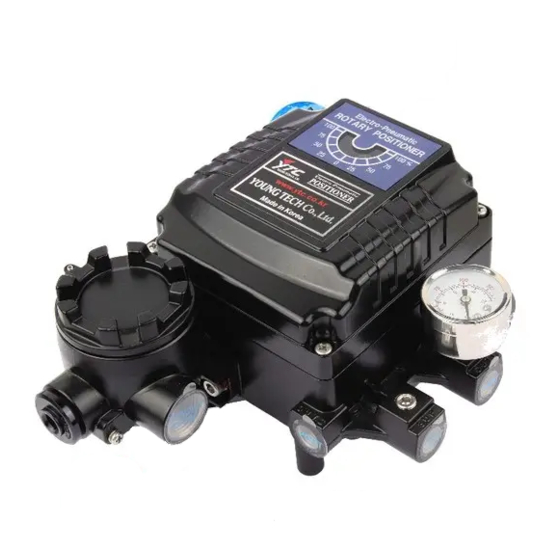
-
Page 2: Table Of Contents
2.6.6 YT-1000R+SPTM+L/S (Internal) ……………………………………………………… 13 2.7 Product Dimension ………………………………………………………………………………… 14 2.7.1 YT-1000L Flameproof Type……………………………………………………………. 14 2.7.2 YT-1000L Intrinsically Safety Type ……………………………………………………. 14 2.7.3 YT-1000R Flameproof Type …………………………………………………………… 14 2.7.4 YT-1000R Intrinsically Safety Type …………………………………………………… 15 2.7.5 YT-1000L+SPTM (Internal) …………………………………………………………….. 15 2.7.6... - Page 3 3.3.2 Installation Steps ………………………………………………………………………… 20 4. Connections …………………………………………………………………………………………….. 21 4.1 Safety ……………………………………………………………………………………………….. 21 4.2 Supply Pressure Condition ……………………………………………………………………….. 21 4.3 Piping Condition ……………………………………………………………………………………. 21 4.4 Connection – Actuator ……………………………………………………………………………... 22 4.4.1 Single acting actuator …………………………………………………………………… 22 4.4.2 Double acting actuator ………………………………………………………………….. 22 4.5 Connection –...
-
Page 4: Introduction
1. Introduction General Information for the users Thank you for purchasing Young Tech Co., Ltd products. Each product has been fully inspected after its production to offer you the highest quality and reliable performance. Please read the product manual carefully prior to installing and commission the product. For the safety, it is important to follow the instructions in the manual. -
Page 5: Product Description
For other certification, please visit Young Tech Co., Ltd website (www.ytc.co.kr) Explosion proof type of cables and gaskets should be used, when explosion gases are present at the installation site. Power should be turned off completely when opening product’s cover. When opening ... -
Page 6: Label Description
Explosion Proof: Indicates certified explosion proof grade. Input Signal: Indicates input signal range. Amb. Temp.: Indicates the allowable ambient temperature. Supply Pressure: Indicates the supply pressure range. Serial Number.: Indicates the unique serial number. Product Number 2.4.1 YT-1000L YT-1000/1050 series... -
Page 7: Yt-1000R
2.4.2 YT-1000R YT-1000/1050 series... -
Page 8: Yt-1050
2.4.3 YT-1050 YT-1000/1050 series... -
Page 9: Product Specification
Product Specification 2.5.1 YT-1000L & R Model YT-1000L YT-1000R Acting Type Single Double Single Double Input Signal 4~20mA DC 250 +/- 15 Ώ Impedance Supply Pressure 0.14~0.7 MPa (1.4~7 bar) Stroke 10~150 mm 0~90° Air Connection PT, NPT 1/4 Gauge Connection... -
Page 10: Yt-1050L & R
2.5.2 YT-1050L & R Model YT-1050L YT-1050R Acting Type Single Double Single Double Input Signal 4~20mA DC 250 +/- 15 Ώ Impedance Supply Pressure 0.14~0.7 MPa (1.4~7 bar) Stroke 10~150 mm 0~90° Air Connection NPT 1/4 Gauge Connection NPT 1/8 Conduit Entry PF(G) 1/2 Protection Grade... -
Page 11: Parts And Assembly
Parts and Assembly 2.6.1 YT-1000/1050L 2.6.2 YT-1000/1050R YT-1000/1050 series... -
Page 12: Yt-1000L+Sptm (Internal)
2.6.3 YT-1000L + SPTM (Internal) 2.6.4 YT-1000R + SPTM (Internal) YT-1000/1050 series... -
Page 13: Yt-1000R+L/S (Internal)
2.6.5 YT-1000R + L/S (Internal) 2.6.6 YT-10000R + SPTM + L/S (Internal) YT-1000/1050 series... -
Page 14: Product Dimension
Product Dimension 2.7.1 YT-1000L Flameproof Type 2.7.2 YT-1000L Intrinsically Safety Type 2.7.3 YT-1000R Flameproof Type YT-1000/1050 series... -
Page 15: Yt-1000R Intrinsically Safety Type
2.7.4 YT-1000R Intrinsically Safety Type 2.7.5 YT-1000L + SPTM (Internal) 2.7.6 YT-1000R + SPTM (Internal) 2.7.7 YT-1000R + SPTM + L/S (Internal) & YT-1000R + Dome indicator YT-1000/1050 series... -
Page 16: Yt-1050L
2.7.8 YT-1050L 2.7.9 YT-1050R YT-1000/1050 series... -
Page 17: Installation
3. Installation Safety When installing a positioner, please ensure to read and follow safety instructions. Any input or supply pressures to valve, actuator, and / or to other related devices must be turned off. Use bypass valve or other supportive equipment to avoid entire system “shut down”. ... - Page 18 5. Connect supply pressure to the actuator temporarily. Supply enough supply pressure to the actuator in order to position the actuator clamp at 50% of the total valve stroke. 6. Insert connection pin into the feedback lever. The pin should be inserted when the actuator clamp is at 50% of the total valve stroke.
-
Page 19: Yt-1000/1050R Installation
air to the actuator (manual position). On both 0% and 100%, the feedback lever should not touch the lever stopper, which is located on the backside of the positioner. If the feedback lever touches the stopper, the positioner should be installed further away from the yoke. -
Page 20: Installation Steps
Markings of bolt holes Actuator stem height (H) 20mm H : 20 H : 20, 30 H : 20 H : 20, 30 30mm H : 30 H : 20, 30 H : 30 H : 20, 30 50mm H : 50 H : 50 H : 50 H : 50... -
Page 21: Connections
5. After setting fork lever position, assemble lock nuts which are located on the bottom of the fork lever. Ensure to set the height of the upper fork lever between 6~11mm, which is lower than the upper bracket’s height. 6. Attach the positioner to the bracket. Fix the clamping pin on the main shaft’s center of the positioner and insert connection pin into the fork... -
Page 22: Connection - Actuator
Pipeline should have more than 6mm of inner diameter (10mm outer diameter) to maintain flow rate. The length of pipeline system should not be extremely long. Longer pipeline system may affect flow rate due to the friction inside of the pipeline. Connection –... -
Page 23: Ground
Positioner should be grounded. Please use twisted cable with conductor section are 1.25mm and that is suitable for 600V (complying to the conductor table of NEC Article 310.) The outer diameter of the cable should be between 6.35 ~ 10mm. Use shield wire to protect against electro- magnetic field and noise. -
Page 24: Sptm & L/S Internal
4.5.5 SPTM & L/S Internal <Option> 5. Adjustments Adjustment – Cam YTC sets positioner as Reverse Action <RA> unless specified otherwise when placing an order. 5.1.1 YT-1000/1050L 5.1.2 YT-1000/1050R YT-1000/1050 series... -
Page 25: Yt-1000/1050R With Internal Options
5.1.3 YT-1000/1050R with Internal Options <Option> Cam can be adjusted for YT-1000/1050R with options by dissembling the cam from the main shaft. After dissembling the cam from the main shaft, please follow 5.1.2 for RA or DA cam. Adjustment – Zero Point 1. -
Page 26: Calibration
will be calculated automatically. 2. 5 Point Setting This setting set 5 points (0%, 25%, 50%, 75%, and 100%). This requires more setting, but feedback setting will be more accurate than 2 point setting. 5.4.2 Calibration 1. Supply 4mA input signal to the positioner and check if valve position made to its target position. -
Page 27: Adjustment - Orifice
Adjustment - Orifice If the actuator size is too small relative to the flow rate, positioner can have hunting / oscillation. In order to avoid hunting, the orifice must be inserted. 1. Remove the pilot relay assembly from the positioner. 2. -
Page 28: Maintenance
6. Maintenance Maintenance on pilot relay valve is recommended to perform at least once a year of with or without operation. When dissembling the pilot relay valve, please be careful not to loose any o- rings or stabilizer spring. Please refer to below instruction and diagram. 1. -
Page 29: Troubleshooting
▶ Actuator only operates by On/Off. (1) Check actuator and positioner's acting type. Air pressure exhausts from YT-1000L's OUT1 port as input signal level increases. Therefore, it is standard to connect to OUT1 port when single actuator is used.
Need help?
Do you have a question about the YT-1000L and is the answer not in the manual?
Questions and answers