Table of Contents
Advertisement
Advertisement
Table of Contents

Subscribe to Our Youtube Channel
Related Manuals for Jet GH-1440


Summary of Contents for Jet GH-1440
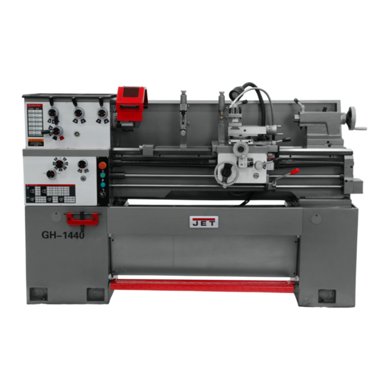
- Page 1 This .pdf document is bookmarked Operating Instructions and Parts Manual Geared Head Lathe 14x40 inch Model GH-1440 427 New Sanford Road LaVergne, Tennessee 37086 Part No. M-322830 Ph.: 800-274-6848 Edition 2 12/2017 www.jettools.com Copyright © 2017 JET...
-
Page 2: Important Safety Instructions
recommended. Wear protective hair covering to contain long hair. Do not wear any type of glove. 15. Always wear ANSI Z87.1 approved safety 1.0 IMPORTANT SAFETY glasses or face shield while using this machine. (Everyday eyeglasses only have INSTRUCTIONS impact resistant lenses; they are not safety glasses.) Read and understand the entire owner's 16. - Page 3 33. Never leave the machine running unattended. 35. Do not operate the lathe in flammable or Turn the power off and do not leave the machine explosive environments. Do not use in a damp until moving parts come to a complete stop. environment or expose to rain.
-
Page 4: Table Of Contents
6.1 Chuck preparation (three jaw) ........................9 7.0 Lubrication ..............................10 8.0 Coolant preparation ............................12 9.0 Electrical connections ..........................12 9.1 Voltage conversion (GH-1440-3 only) ...................... 12 10.0 General description ............................ 13 11.0 Operation ..............................16 11.1 Break-in procedure ..........................16 11.2 Feed and thread selection ........................ -
Page 5: About This Manual
Note: The Figures in this manual may or may not show your exact lathe model, but the procedures will be identical. If there are questions or comments, please contact your local supplier or JET. JET can also be reached at our web site: www.jettools.com. -
Page 6: Specifications
4.0 Specifications Table 1 Model number GH-1440-1 GH-1440-3 Stock number 322830 322840 Motor and Electricals Motor type TEFC induction Horsepower 3 HP (2.2 kW) Phase single Voltage 230V only 230/460V (prewired 230V) Cycle 60 Hz Listed FLA (full load amps) 18 A 8.3 / 4.2 A... -
Page 7: Cross Slide T-Slot Dimensions
= not applicable The specifications in this manual were current at time of publication, but because of our policy of continuous improvement, JET reserves the right to change specifications at any time and without prior notice, without incurring obligations. -
Page 8: Uncrating
5.0 Uncrating Open shipping crate and check for shipping damage. Report any damage immediately to your distributor and shipping agent. Do not discard any shipping material until the Lathe is assembled and running properly. Compare the contents of your crate with the following parts list to make sure all parts are intact. -
Page 9: Installation
6.0 Installation Finish removing the wooden crate from around the lathe. Unbolt the lathe from the shipping crate bottom. Choose a location for the lathe that is dry, has good lighting, and has enough room to service the lathe on all four sides Place two steel rods or pipes (of sufficient strength) into four holes (A, Fig. -
Page 10: Lubrication
Cover all chuck jaws and scroll inside the chuck with Mobilith® AW2. Cover the spindle, cam locks, and chuck body with a light film of Mobil DTE® Oil Heavy Medium. Lift the chuck up to the spindle nose and press onto the spindle. - Page 11 Apron – Oil must be up to indicator mark in oil sight glass (A, Fig. 7). Top off with Mobil DTE® Oil Heavy Medium. Remove oil cap (B, Fig. 7) on top of apron to fill. To drain, remove drain plug on bottom of apron. Drain oil completely and refill after the first month of operation.
-
Page 12: Coolant Preparation
460V terminal as outlined on the shock and possible fatal injury. transformer. The GH-1440-1 lathe is rated at 3HP, single- Coolant Pump: Open access panel on base at phase, 230V only. The GH-1440-3 lathe is rated tailstock end. -
Page 13: General Description
10.0 General description Lathe bed The lathe bed (A, Fig. 11) is made of high grade cast iron. By combining high cheeks with strong cross ribs, a bed with low vibration and high rigidity is realized. Two precision ground v-slideways, reinforced by heat hardening and grinding, are an accurate guide for the carriage and headstock. - Page 14 Gear box The gear box (D, Fig. 13) is made from high quality cast iron and is mounted to the left side of the machine bed. Steady rest The steady rest (E, Fig. 13) serves as a support for shafts on the free tailstock end. The steady rest is mounted on the bedway and secured from below with a bolt, nut and locking plate.
- Page 15 Headstock Gear Change Levers (E, Fig. 14) – located on front of headstock. Move levers according to speed chart for desired setting. Leadscrew/Feed Rod Directional Lever (F, Fig. 14) – located on front of headstock. Moving the lever up causes carriage travel toward the tailstock;...
-
Page 16: Operation
12. Half Nut Engage Lever (thread cutting) (F, Fig. 15) – located on front of the apron. Move the lever down to engage. Move the lever up to disengage. 13. Cross Traverse Handwheel (G, Fig. 15) – located above the apron assembly. Rotate clockwise or counter-clockwise to move, or position. -
Page 17: Feed And Thread Selection
11.2 Feed and thread selection Refer to the feed and thread charts found on the gear box faceplate (A, Fig. 18 and sect. 13.0 of this manual). Move levers (B, C, D, E, F, Fig. 18) to the appropriate positions according to the chart. 11.3 Change gears replacement The 25T, 127T, 50T gears are installed in the end gear compartment when delivered from the factory. -
Page 18: Powered Carriage Travel
11.5 Powered carriage travel Push lever (B, Fig. 20) to the left and down to engage crossfeed. Pull lever to the right and up to engage longitudinal feed. 11.6 Thread cutting Set forward/reverse lever (A, Fig. 20) up or down depending on the desired direction. Set selector levers (A, B, C, D, Fig. -
Page 19: Cross Slide
Move the carriage again and readjust if necessary. Note: Over-adjustment will cause excessive and premature wear of the gibs. 12.2 Cross slide If the cross slide is too loose, follow procedure below to tighten: Loosen the rear gib screw (not shown) approximately one turn. -
Page 20: Headstock Alignment
12.7 Headstock alignment The headstock has been aligned at the factory and should require adjustment. However, adjustment is deemed necessary, follow the procedure below to align the headstock: Using a machinist's precision level on the bedways, make sure the lathe is level side to side and front to back. -
Page 21: Belt Replacement And Adjustment
12.10 Belt replacement and adjustment Disconnect machine from power source (unplug). Open the end gear cover and lower cover on the headstock side. Take tension off old belts by loosening motor mount hex nut (A, Fig. 27). Remove belts. Install new belts onto pulleys. Tension by tightening motor mount hex nut until 8 lbs. -
Page 22: Operation Tables
Number of your machine available when you call will allow us to serve you quickly and accurately. Non-proprietary parts, such as fasteners, can be found at local hardware stores, or may be ordered from JET. Some parts are shown for reference only, and may not be available individually. -
Page 23: Headstock Assembly I - Exploded View
14.1.1 Headstock Assembly I – Exploded View... -
Page 24: Headstock Assembly I - Parts List
14.1.2 Headstock Assembly I – Parts List Index No. Part No. Description Size 1 ....C6136-02755 .... Plug........................ 1 2 ....GH1440K-02119 ..Headstock Cover ................... 1 3 ....TS-1503061 ....Hex Socket Hd Cap Screw ........M6x25 ......6 4 .... - Page 25 Index No. Part No. Description Size 142 .... GH1440K-142 ... O-Ring ..............25x2.65 mm ....3 159 .... TS-1506041 ....Hex Socket Hd Cap Screw ........M12x35 ......2 160 .... GH1440K-02304-24 .. Name Plate ....................1...
-
Page 26: Headstock Assembly Ii - Exploded View
14.2.1 Headstock Assembly II – Exploded View... -
Page 27: Headstock Assembly Ii - Parts List
14.2.2 Headstock Assembly II – Parts List Index No. Part No. Description Size 61 ....TS-1504031 ....Hex Socket Hd Cap Screw ........M8x16 ......1 62 ....04-12 ......Washer ......................1 63 ....04-11 ......Pulley ......................1 64 .... -
Page 28: Headstock Assembly Iii - Exploded View
14.3.1 Headstock Assembly III – Exploded View... -
Page 29: Headstock Assembly Iii - Parts List
14.3.2 Headstock Assembly III – Parts List Index No. Part No. Description Size 56 ....TS-150303 ....Hex Socket Hd Cap Screw ........M6x12 ......18 61 ....TS-1504031 ....Hex Socket Hd Cap Screw ........M8x16 ......3 74 ....F006050 ....C-Retaining Ring, Ext ..........25 mm ......6 82 .... -
Page 30: Gearbox Assembly I - Exploded View
14.4.1 Gearbox Assembly I – Exploded View... -
Page 31: Gearbox Assembly I - Parts List
14.4.2 Gearbox Assembly I – Parts List Index No. Part No. Description Size 1 ....05-73 ......Plug........................ 1 2 ....GH1440K-05101 ..Gearbox Casting .................... 1 3 ....05-07 ......Front Cover ....................1 4 ....TS-1512011 ....Socket Flat Head Screw .......... M4x10 ......8 5 .... - Page 32 Index No. Part No. Description Size 64 ..... GH1440K-05301-19 .. Name Plate ....................1 65 ....GB2672 ..... Screw ............... M3x6 ......6 66 ..... GH1440K-05303 ..Graphic Plate - Speed Chart ................. 1...
-
Page 33: Gearbox Assembly Ii - Exploded View
14.5.1 Gearbox Assembly II – Exploded View... -
Page 34: Gearbox Assembly Ii - Parts List
14.5.2 Gearbox Assembly II – Parts List Index No. Part No. Description Size 1 ....TS-1503041 ....Hex Socket Cap Screw ..........M6x16 ......1 2 ....05-42 ......Washer ......................1 3 ....05-41 ......Gear ................. 52T ........ 1 4 .... - Page 35 Index No. Part No. Description Size 58 ....GH1440K-05705 ..Shaft ......................1 59 ....GH1440A-05307 ..Shaft Collar ....................1 60 ....05-18 ......Flange ......................1 61 ....05-20 ......Nut ......................... 2 62 ....GH1440K-05726 ..Collar ......................1 63 ....
-
Page 36: Apron Assembly I - Exploded View
14.6.1 Apron Assembly I – Exploded View... -
Page 37: Apron Assembly I - Parts List
14.6.2 Apron Assembly I – Parts List Index No. Part No. Description Size 1 ....TS-1503021 ....Hex Socket Hd Cap Screw ........M6x10 ......2 2 ....06-37 ......Half Nut ......................1 3 ....06-36 ......Bracket......................1 4 .... -
Page 38: Apron Assembly Ii - Exploded View
14.7.1 Apron Assembly II – Exploded View... -
Page 39: Apron Assembly Ii - Parts List
14.7.2 Apron Assembly II – Parts List Index No. Part No. Description Size 36 ....06-44 ......Bushing ......................1 37 ....06-43 ......Shaft ......................1 38 ....F006044 ....C-Retaining Ring, Ext ..........16 mm ......1 39 .... -
Page 40: Saddle And Cross Slide Assembly - Exploded View
14.8.1 Saddle and Cross Slide Assembly – Exploded View... -
Page 41: Saddle And Cross Slide Assembly - Parts List
14.8.2 Saddle and Cross Slide Assembly – Parts List Index No. Part No. Description Size 1 ....GH1440K-04702 ..Gib ......................... 1 2 ....GH1440A-04728 ..Gib Adjusting Screw ..................2 3 ....TS-1533032 ....Pan Head Machine Screw ........M5x10 ......5 5 .... - Page 42 Index No. Part No. Description Size 65 ....GHB1340A-04788 ..Pin........................1 66 ....GHB1340A-04507 ..Sleeve ......................1 67 ....GH1440K04303 ..Plate....................... 1...
-
Page 43: Top Slide And Tool Post - Exploded View
14.9.1 Top Slide and Tool Post – Exploded View... -
Page 44: Top Slide And Tool Post - Parts List
14.9.2 Top Slide and Tool Post – Parts List Index No. Part No. Description Size 1 ....GH1440A-04707 ..Tool Post......................1 2 ....GB83-88 ....Tool Lock Screw ............10x50 mm ..... 8 3 ....C0632-04704 .... Handle Hub ....................1 4 .... -
Page 45: Tailstock Assembly - Exploded View
14.10.1 Tailstock Assembly – Exploded View... -
Page 46: Tailstock Assembly - Parts List
14.10.2 Tailstock Assembly – Parts List Index No. Part No. Description Size 1 ....GH1440A-03703A ..Index Ring ..................... 1 2 ....TS-1503051 ....Hex Socket Hd Cap Screw ........M6x20 ......3 3 ....GH1440K-03102 ..Hub ........................ 1 4 .... -
Page 47: Bed And Shaft Assembly - Exploded View
14.11.1 Bed and Shaft Assembly – Exploded View... -
Page 48: Bed And Shaft Assembly - Parts List
14.11.2 Bed and Shaft Assembly – Parts List Index No. Part No. Description Size 1 ....GH1440K-01101 ..Bed ........................ 1 2 ....GH1440A-01704 ..Rack (short) ....................1 3 ....TS-150306 ....Hex Socket Cap Screw ..........M6x25 ......8 4 .... - Page 49 Index No. Part No. Description Size 58 ....F010448 ....Socket Set Screw DP ..........M8x16 ......1 59 ....C0632A-01504 ..Shaft Box Cover..................... 1 60 ....TS-1502021 ....Socket Head Cap Screw ......... M5x10 ......4...
-
Page 50: Stand And Brake Assembly - Exploded View
14.12.1 Stand and Brake Assembly – Exploded View... -
Page 51: Stand And Brake Assembly - Parts List
38 ....GH1440K-01706 ..Front Plate ..................... 1 39 ....GH1440K-01701 ..Brake Pedal ....................1 40 ....JET-165 ..... JET Logo ..............165x68mm ....1 41 ....C0632A-22704 ..Shaft ......................1 42 ....2210-108 ....Spring Pin ..............M5x30 ......3 43 .... -
Page 52: End Gear Assembly - Exploded View
14.13.1 End Gear Assembly – Exploded View... -
Page 53: End Gear Assembly - Parts List
14.13.2 End Gear Assembly – Parts List Index No. Part No. Description Size 1 ....TS-1502041 ....Hex Socket Hd Cap Screw ........M5x16 ......1 2 ....GH1440K-1304 ..Washer, spcl ............6 mm ......1 3 ....04-50 ......Gear ................. 25T ........ 1 4 .... -
Page 54: Follow Rest - Exploded View
14.14.1 Follow Rest – Exploded View 14.14.2 Follow Rest – Parts List Index No. Part No. Description Size ....GH1440K-FRA ..Follow Rest Assembly (#1 thru 10) ..............1 ....GH1440-09-02 ..Knob ......................2 2 ....TS-1523011 ....Socket Set Screw ............ M6x6 ......2 3 .... -
Page 55: Thread Dial Assembly - Exploded View
14.15.1 Thread Dial Assembly – Exploded View 14.15.2 Thread Dial Assembly – Parts List Index No. Part No. Description Size ....GH1440K-TDA ..Thead Dial Assembly (includes #1 thru 9) ............1 ....06-22 ......Dial......................... 1 2 ....GB879-3x12 ....Spring Pin ..............3x12 ......1 3 .... -
Page 56: Steady Rest - Parts List
14.16.1 Steady Rest – Parts List... -
Page 57: Steady Rest - Parts List
14.16.2 Steady Rest – Parts List Index No. Part No. Description Size ....GH1440K-SRA ..Steady Rest Assembly (#1 thru 21) ............... 1 1 ....GH1440-09-02 ..Knob ......................3 2 ....TS-1523011 ....Socket Set Screw ............ M6x6 ......3 3 .... -
Page 58: Coolant And Work Light Assembly - Exploded View
14.17.1 Coolant and Work Light Assembly – Exploded View 14.17.2 Coolant and Work Light Assembly – Parts List Index No. Part No. Description Size 1 ....GHB1340-EL ..... Work Light...................... 1 2 ....TS-1503051 ....Hex Socket Hd Cap Screw ........M6x20 ......3 3 .... -
Page 59: Chuck Guard Assembly - Exploded View
14.18.1 Chuck Guard Assembly – Exploded View 14.18.2 Chuck Guard Assembly – Parts List Index No. Part No. Description Size ....GH1440K-CGA ..Chuck Guard Assembly (#1 thru 19) ............1 1 ....GH1440K-19701J ..Chuck Guard ..................... 1 2 .... -
Page 60: Lead Screw Cover Assembly - Exploded View
14.19.1 Lead Screw Cover Assembly – Exploded View 14.19.2 Lead Screw Cover Assembly – Parts List Index No. Part No. Description Size 1 ....GH1440K-14701 ..Left Flange ..................... 1 2 ....TS-1502031 ....Hex Socket Hd Cap Screw ........M5x12 ......2 3 .... -
Page 61: Accessories I - Exploded View
14.20.1 Accessories I – Exploded View... -
Page 62: Accessories I - Parts List
14.20.2 Accessories I – Parts List Index No. Part No. Description Size ....GH1440-TBCP ..Tool Box Complete (#1 thru 28)..............1 1 ..........Tool Box......................1 2 ....GH1440-0611 .... Handle Sleeve ....................1 ....GH1440-0610 .... Handle Lever ....................1 3 .... -
Page 63: Accessories Ii - Exploded View
14.21.1 Accessories II – Exploded View 14.21.2 Accessories II – Parts List Index No. Part No. Description Size 1 ....K72200D4 ....Four Jaw Chuck with Camlock Stud ......8" ........1 2 ....K11160AD4 ....Three Jaw Chuck with Camlock Stud (Direct Mount)…6" ......1 3 .... -
Page 64: Electrical Components - Exploded View
14.22.1 Electrical Components – Exploded View 14.22.2 Electrical Components – Parts List Index No. Part No. Symbol* Description Size 1 ....GH1440K-KM1 ..KM1 ....Magnetic Starter ........ LC1-D2501 ....1 2 ....GH1440K-KM1 ..KM2 ....Magnetic Starter ........ LC1-D2501 ....1 3 .... -
Page 65: Electrical Connections
15.0 Electrical Connections 15.1 Wiring Diagram – 1 Phase... -
Page 66: Wiring Diagram - 3 Phase
15.2 Wiring Diagram – 3 Phase... -
Page 67: Warranty And Service
JET sells through distributors only. The specifications listed in JET printed materials and on official JET website are given as general information and are not binding. JET reserves the right to effect at any time, without prior notice, those alterations to parts, fittings, and accessory equipment which they may deem necessary for any reason ®... - Page 68 427 New Sanford Road LaVergne, Tennessee 37086 Phone: 800-274-6848 www.jettools.com...
Need help?
Do you have a question about the GH-1440 and is the answer not in the manual?
Questions and answers