Table of Contents
Advertisement
Quick Links
Advertisement
Table of Contents

Related Manuals for FrSky HORUS X10S


Summary of Contents for FrSky HORUS X10S
- Page 1 Note: We will keep improving the instruction manual. Any ambiguities or mistakes please contact us: frsky@frsky-rc.com Any technical problems please contact: sales4tech@gmail.com More information please refer to FrSky website: www.frsky-rc.com...
- Page 2 FrSky HORUS X10S Manual V1.0.0 FrSky Electronic Co., Ltd. www.frsky-rc.com 15 December 2017 Page 1 15 December 2017...
-
Page 3: Introduction
RESTRICTIONS ON SALES AND TERRITORY If you have any questions or service request, please contact your local FrSky dealer(s). It should be noted that all information and technical support provided in the manual only pertains to the devices sold within your region, and may be different from devices purchased in other regions. -
Page 4: Charge Transmitter Battery Before Use
3. Repair, adjustment and replacement of parts. FrSky cannot be held responsible for any unauthorized repair, adjustment and/or replacement of parts. All modifications to the product other than those undertaken by an approved dealer will render the warranty void. CHARGE TRANSMITTER BATTERY BEFORE USE The X10/X10S is equipped with a 2s 2600mAh Li-ion battery pack. -
Page 5: Table Of Contents
TABLE OF CONTENTS INTRODUCTION ..........................2 User’s Manual And Technical Support ....................2 Restrictions On Sales And Territory ....................2 Provisions On Use, Export And Quality Guarantee................2 Charge Transmitter Battery Before Use .................... 3 Table Of Contents .......................... 4 User Safety Notes .......................... - Page 6 SYSTEM MENU ......................... 24 MODEL SEL .......................... 25 TIME ............................. 27 DISPLAY ..........................28 SOUND ..........................29 BATTERY ..........................29 STICK CAL ..........................30 STICK DIR ..........................31 UPDATE ..........................32 WL TELE ..........................33 6.10 SXR SETUP ..........................33 6.11 INFORMATION ........................
- Page 7 FLIGHT MODES ....................... 58 7.1.19 RATES/EXPO ......................59 7.1.20 THROTTLE CUT ...................... 60 7.1.21 THROTTLE HOLD ....................62 7.1.22 THROTTLE CURVE ....................63 7.1.23 V-TAIL ........................64 7.1.24 EXTRA MIXER ......................65 7.1.25 MODEL (HELICOPTER) ......................69 PITCH CURVE ......................70 7.2.1 THROTTLE MIX ......................
- Page 8 RUDDER SETUP ......................103 7.4.4 MOTOR........................104 7.4.5 MODEL (MULTIcopter) ...................... 105 MODE .......................... 105 7.5.1 GYRO ........................... 106 7.5.2 MODEL (CUSTOM) ......................106 MIXER ......................... 106 7.6.1 TELEMETRY MENU ....................... 110 TELEMETRY MENU ......................110 TELEMETRY SETUP MENU ....................112 DATA STORAGE ........................
- Page 9 10.19 S ............................126 10.20 T ............................127 10.21 U ............................127 10.22 V ............................127 10.23 W ............................128 10.24 X ............................128 10.25 Y ............................128 10.26 Z ............................128 Page 8 15 December 2017...
-
Page 10: User Safety Notes
2 USER SAFETY NOTES Please read the following thoroughly for your own safety. 2.1 MEANING OF SYMBOLS Contents marked with one of the following symbols in the manual require immediate attention: DANGER: This action can lead to death or serious injury to the user and/or others. -
Page 11: At The Flying Field
2.5 SAFE USE AND HANDLING OF THE LI-ION BATTERIES The user should only use power adapters with/without FCX10 supplied by FrSky or those that are approved by FrSky to charge the battery inside the HORUS X10/X10S transmitter. It is important to be aware about the characteristics of the Li-ion battery. If you do not follow... -
Page 12: Microsd Handling Recommendations
NOTE: There are two type of charge systems of Horus X10/X10S. To charge the transmitter, plug the FrSky -provided power adapter cable connector into the transmitter charging port and the power adapter into an AC electrical outlet. - Page 13 CAUTION: Keep microSD card clean, avoid direct sunlight, and stay from moisture/water and/or any other type of potentially corrosive liquids. WARNING: Never store the microSD card in an environment subjected to strong electromagnetism. NOTE: Always check the orientation of the microSD card before inserting to ensure correct installation.
-
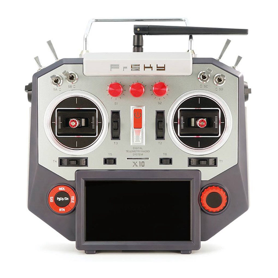
Page 14: Transmitter Hardware
External RF module bay Six trim operating buttons Six three position, one two position and one momentary switch FrSky FrTX operation system installed and open source system (openTX) supported Flight simulator (PC) compatible Logic switch programming ... -
Page 15: Display
Hall Effect angle sensors, for superior quality feel, precision and durability. NOTE: The X10S is equipped with FrSky newly developed MC12 Plus gimbal with more precisely PWM output which X10 can be upgraded to install as well. 3.5 HAPTIC FEEDBACK A programmable feature notifies the operator by vibrating the transmitter, it can be selected for a wide variety of functions. -
Page 16: Apps Supported For Telemetry
3.9 APPS SUPPORTED FOR TELEMETRY Support FrSky Free Link App for telemetry (download address: http://www.frsky- rc.com/app/). 3.10 LAYOUT 3.11 The storage system There is an internal flash IC installed in the radio and a microSD slot is provided in the rare of the radio. -
Page 17: Micro Sd Card (Secure Digital Memory Card)
3.11.2 MICRO SD CARD (SECURE DIGITAL MEMORY CARD) The transmitters’ microSD Slot supports microSD and Micro SDHC type cards. When installed correctly a microSD card icon will be displayed in the top right corner of the screen. There are certain files that require to be stored on the microSD Card such as: telemetry log and update files. -
Page 18: Avigate The Menu
AVIGATE THE MENU 4.1 HOW TO NAVIGATE THE MENUS To navigate the menus, the transmitters of the HORUS series have the following elements: 4 buttons (in red on the drawing): ◦ SYS – For direct access to the SYSTEM menu ◦... - Page 19 Page 18 15 December 2017...
-
Page 20: Overview Of The Menu Tree
4.3 OVERVIEW OF THE MENU TREE 4.4 QUICK SELECT OPTIONS Long press “TELE” button: this will generate a pop-up where the user can reset timer, reset telemetry values, reset all above, jump to tele setup page. Overview of the switch warning reset menu screen Page 19 15 December 2017... - Page 21 Long press “RTN” button: this will instantly bring the user to the “MONITOR” menu, pressing “RTN” again, will return the user back to the previously opened menu. Long press “PgUp/Dn” button for 3 seconds: this will (de)activate the button lock function, a lock icon will be displayed on the top right corner of the screen when activated.
-
Page 22: Home Screen
5 HOME SCREEN Home screen (page 1/3) The illustration above is the home screen of the transmitter (page 1/3), the picture of the airplane can be made and/or selected by users representing the selected model. The currently selected flight mode, and throttle position (%) are displayed in the top left. - Page 23 NOTE: Yellow triangle on the icon means that the device is not well detected or not working properly. Setting up timer The illustration below is an example of the “TIMER” menu, to choose between the two available timer menus rotate the rotary button while being on the home screen, press “ENTER”...
- Page 24 Home screen (page 2/3) The home screen page 2/3 can be used to check if the sticks, switches, sliders and knobs Home screen (page 3/3) The home screen page 3/3 illustrates the status of the programed logic switch lines, the programming line gets a white bar to indicate that the preassigned conditions are met.
-
Page 25: System Menu
“BATTERY”: Displays the transmitter battery voltage, of which the range can be changed to accommodate battery’s other than the one supplied by FrSky. The low-battery warning voltage and the range of the... -
Page 26: Model Sel
“WL TELE”: Allows the user to turn on/off the Bluetooth, which is used to transmit the data of flight information to the cellphone through the App which can be downloaded from http://www.frsky-rc.com/app/. “SXR SETUP”:Displays the wing type of the plane and the mounting type of the receiver (horizontal/vertical) only when the SXR receiver is connected to the transmitter. - Page 27 The illustration above is an example of the “STICK MODE” menu that is used when creating a new model. Here the user can choose one of the four available stick modes (MODE 1-4), this must correspond with the actual transmitter stick layout. Description of MODE naming Overview of the model creation menu screen The illustration above is an example of the “MODEL CREATE”...
-
Page 28: Time
Overview of the model modify menu screen CAUTION: Changing TYPE will result in the deletion of all settings, as channel order and/or function change, making these setting obsolete. Keep this in mind when using this menu option. TIME Overview of the time menu screen The illustration above is an example of the “TIME”... -
Page 29: Display
DISPLAY Overview of the display menu screen The illustration above is an example of the “DISPLAY” menu, to enter this menu press the “SYS” button, then select “DISPLAY”. Here the user can adjust the brightness of the screen and activate the sleep function. According to personal preference and changes on brightness, a knob can be assigned to manually change the brightness to achieve the desired visual effect. -
Page 30: Sound
SOUND Overview of the sound menu screen The illustration above is an example of the “SOUND” menu, to enter this menu press the “SYS” button, then select “SOUND”. Here the user can adjust the volume of the key, alarm and trim beeps. They can be individually adjusted or all muted (QUIET). Selecting “POT” option, the knobs and/or sliders can be used to individually adjust the volume without entering the menu. -
Page 31: Stick Cal
BATTERY VOLTAGE” (0.0-16.0V). This allows to make room for the battery evolution and improve the compatibility with multiple types of batteries. The battery voltage under the option of BATTERY is an accurate value, thus recalibration is very unlikely to be required. If changing by mistake, press the “Reset all to defaults”. -
Page 32: Stick Dir
NOTE: We advise you to regularly check the produced output signals and to recalibrate the transmitter when it has not been used for a long period of time. NOTE: You can use this menu to readjust the zero/neural position starting the calibration process with the desired hardware input at an endpoint. -
Page 33: Update
Overview of the stick direction menu screen The illustration above is an example of the “STICK DIRECTION” menu, to enter this menu press the “SYS” button, then select “STICK DIRECTION”. Here the user can reverse the signal direction of all hardware signals. -
Page 34: Wl Tele
“SYS” button, then select “UPDATE”. Here the user could apply the files in the SD card to update the firmware of FrSky products with S.Port and delete them. For example, if you want to update/delete the first file, move the cursor to the first one and press ENT Button. -
Page 35: Information
The illustration above is an example of the “SXR SETUP” menu, to enter this menu press the “SYS” button, then select “SXR SETUP”. If a SXR receiver has been bound to the transmitter, the wing type and mounting type of the plane will be displayed on the screen. 6.11 INFORMATION Overview of the information menu screen The illustration above is an example of the “INFORMATION”... -
Page 36: Model Menu
7 MODEL MENU The “MODEL” (MDL button) menu is used to set up the selected model, the content of this menu changes with the type of model selected. There are predefined mixes. Press PgUp/Dn to switch between the menu pages. The first section of this chapter contains the shared menus, thereafter it is divided into the available model types/variations, except for fixed wing that also contains glider related menus, type specific menus will be discussed in their own sub chapter. -
Page 37: Rf System
Overview of the model menu screen 7.1.1 RF SYSTEM The illustration below is an example of the “RF SYSTEM” menu, to enter this menu press the “MDL” button, then select “RF SYSTEM”. Here the user can turn the internal and external RF modules on or off, as well as choosing the receiver type and the number of channels to be used. -
Page 38: Internal Rf Module
When using an external DJT/XJT module, the available features are identical to the internal RF module. When using non-FrSky external RF Modules the user first needs to acquire the operating characteristics and requirements of the module before selecting the required PPM setting. -
Page 39: Monitor
PPM + & PPM mode have the signals reversed. Connect the external RF to the transmitter. If the user don’t choose the S.P. connection, S.P: the data send by the receiver couldn’t be transmitted to the transmitter. R9M: If an R9M receiver has been connected to the transmitter, select it and you are available to adjust the transmitting power (10mw, 100mw, 500mw and 1000mw For Non- EU version). -
Page 40: Reverse
Selecting “NEUTRAL” or “MOVING” will activate the throttle channel, DANGER: and under electric-powered models, it will lead to the spool up of the motor! PLEASE disconnect the throttle channel before entering the test mode in case of accidents! NOTE: At any time you can press and hold the “RTN” button to instantly jump to the “Monitor”... -
Page 41: End Point
Overview of the speed menu screen The illustration below is an example of the “SPEED” menu, to enter this menu press the “MDL” button, then select “SPEED”. Here the user can adjust the servo cycle duration time (0s-10.0s in both directions) by adjusting the values for the corresponding channel. The higher the value, the longer it takes for the servo to reach its programmed end point. -
Page 42: Sub Trim
After setting up the “LIMIT”, the servo will never exceed this programmed limit, even if an activated mix demands an increase of servo travel, thus to prevent damage to the servo and/or control service hardware. The normal “TRAVEL” range must also be set up in this menu, thus to determine the normal travel range. -
Page 43: Fail Safe (D16 Rf Mode Only)
Overview of the trim setup menu screen The illustration above is an example of the “TRIM SETUP” menu, to enter this menu press the “MDL” button, then select “TRIM SETUP”. Here the user can customize the step size of the six available trim buttons. If the selected model supports multiple flight modes, the following options are available on the bottom right of the screen. -
Page 44: Logic Switch
The illustration above is an example of the “FAIL SAFE” menu, to enter this menu press the “MDL” button, then select “FAIL SAFE”. The “FAIL SAFE” feature establishes pre-set functions that the receiver will initiate if the control link back to the transmitter is lost. The PgUp/Dn button can be used to switch between the menu pages. - Page 45 Overview of the logic switch overview menu screen The illustration above is an example of the “LOGIC SW” menu, to enter this menu press the “MDL” button, then select “LOGIC SW”. The application of Logic Switches and Special function provide the possibility to create powerful customized functions that are not pre- built in the system.
- Page 46 Left side of the screen “OP.”: Represents the Boolean Operator that can be selected, <, =, >, AND, OR, XOR, NOT “SRC TYPE”: Represents the first source of the logic that can be selected (POT, SW, CHANNEL, LOGIC_SW, CONST, TELEMETRY and TIMER). “SRC 1”: Represents the item within the “SRC TYPE”...
-
Page 47: Curve Library
the “SPECIAL FUNTIONS” menu so The next step could be to use LSW 1 in when LSW 1 is true (RSSI less than 45) a custom “track” will be played. 7.1.10 CURVE LIBRARY Page 46 15 December 2017... - Page 48 Overview of the curve library menu screen The illustration above is an example of the “CURVE LIB” menu, to enter this menu press the “MDL” button, then select “CURVE LIB”. Here the user can create custom curves that Page 47 15 December 2017...
- Page 49 can be used via “MIXER”, the operation of this menu is similar to setting up “EXPO” and “MIXER”. Up to a hundred curves can be created when using custom type, all other model types support fifteen. The names can be customized to easily find the curve during “MIXER” programming.
-
Page 50: Special Function
NOTE: IMPORT and EXPORT curve file location on microSD Card: \SYSTEM\curves\ 7.1.11 SPECIAL FUNCTION Overview of the special function menu screen The illustration above is an example of the “SPECIAL FUNCTION” menu, to enter this menu press the “MDL” button, then select “SPECIAL FUN”. Here the user can program the transmitter to produce alerts, sound and haptic, and play the values of telemetry data,... - Page 51 Allows selection of the action to be assigned when the switch is operated. The options choose from are: “Play Track”: Is used to assign a sound track to be played when a switch is triggered. “Play Value”: Is used to assign a switch to call out a predetermined telemetry value. “Haptic”: Allows the activation of the haptic feature when operating a switch or knob.
-
Page 52: Telemetry Setup
NOTE: The user can instantly assign a knob or switch simply by operating it while the applicable menu option is mounted. 7.1.12 TELEMETRY SETUP Overview of the telemetry setup menu screen The illustration above is an example of the “TELEMETRY SETUP” menu, to enter this menu press the “MDL”... -
Page 53: Switch Warning
Overview of the general menu screen The illustration above is an example of the “GENERAL” menu, to enter this menu press the “MDL” button, then select “GENERAL”. Here the user can deactivate menu features such as start-up sound, pop-ups and warnings. CAUTION: Users are advised that warnings should not be deactivated except in exceptional circumstances. -
Page 54: Trainer
NOTE: Warnings can be deactivated in GENERAL menu when the transmitter in power on. Please refer to chapter 6.1.13. 7.1.15 TRAINER Overview of the trainer menu screen The illustration above is an example of the “TRAINER” menu, to enter this menu press the “MDL”... - Page 55 “PERCENT”: Allows the reduction of the travel range of the selected channels, thus allowing students to fly with reduced rates. The default value is 50 and the range of the percent is 0-100. “SOURCE”: Allows to change the channel arrangement to support multiple “STICK MODES”...
-
Page 56: Tele Cal
NOTE: In order to pair the transmitters the user must first choose “SLAVE” as type and turn on the student’s transmitter (also as slave), then turn on “MASTER” side. NOTE: Wireless trainer can only be used when both users are using a HORUS transmitter. -
Page 57: Input Map
The names of parameters are explained at Pg.1 The second column of the screen The values of the options in the first column. The last two column of the screen The minimum and maximum values. 7.1.17 INPUT MAP Overview of the input map menu screen The illustration above is an example of the “INPUT MAP”... -
Page 58: Output Map
CAUTION: Always check for correct system operation, after making changes to the INPUT MAP. Failure to do so can lead to unexpected system behaviour, and may result in damage and/or serious injury. 7.1.18 OUTPUT MAP Overview of the output map menu screen The illustration above is an example of the “OUTPUT MAP”... -
Page 59: Flight Modes
7.1.19 FLIGHT MODES Overview of the flight mode (helicopter) menu screen The illustration above is an example of the helicopter “FLIGHT MODE” menu. To enter this menu, press the “MDL” button and move to the second page, selecting “FLIGHT MODE”. The user can program up to nine different flight conditions when using “CUSTOM”... -
Page 60: Rates/Expo
The illustration above is an example of the glider “FLIGHT MODE” menu, operation is identical to the other model types. Priority starts with “LANDING” degrading upward resulting in that “NORMAL” is the lowest. The illustration above is an example of the custom “FLIGHT MODE” menu, operation is identical to the other model types. -
Page 61: Throttle Cut
rates and exponential to create custom curves that can be assigned to a switch or “FLIGHT MODE”. The operation of this menu is similar to setting up “CURVE LIB” and “MIXER”. Left side of the screen Depending on the selected model type the user can either assign “FLIGHT MODES” or switches (Helicopter only) to active the programmed curve. - Page 62 Overview of the throttle cut menu screen The illustration above is an example of the “THR CUT” menu. To enter this menu, press the “MDL” button and move to the second page, then select “THR CUT”. Here the user can set up the “throttle cut” on IC engines, or a throttle deactivation switch on electric- powered models.
-
Page 63: Throttle Hold
step is to set up the save position by mounting “SF POS” and set it at -100 to -125 depending on the programmed “end point” of the throttle channel. Left side of the screen Depicts a visual aid to assist the user during programming. Right side of the screen “ACT/INH”: Represents activating/Inhabiting the function “SW”: Represents Switch, SWx, SWEXTER, SWFLP, LSW. -
Page 64: Throttle Curve
hold, the second step is to decide the throttle setting to which the setting should go to when activated. NOTE: If your model is equipped with a throttle governor, there is no need to activate the throttle hold function of the transmitter. Please refer to the manual of your governor system. -
Page 65: V-Tail
Depending on the selected model type the user can either assign “FLIGHT MODES” or switches (Airplane only) to active the programmed curve. Centre of the screen “EXP”, “LINE” and “SMOOTH” are the types of programming option available to the user. “EXP”... -
Page 66: Extra Mixer
“ELEVATOR UP/DOWN” is to set up the travel range and correlation between the rudder and elevator channel when applying the elevator. “RUDDER&ELE LEFT/RIGHT” is to set up the travel range and correlation between the rudder and elevator channel when applying the rudder. Bottom of the screen Depending on the selected model type, the user can either assign “FLIGHT MODE”... - Page 67 * multiply by : replace with “SCR”: Source, allows the user to assign a hardware input to operate the “MIXER” “SW”: Switches, allows to assign an activation switch to turn the mix on or off, this can be done with hardware switches and logic switches. “F.MODE”: Flight mode, allows to determine during which mode the mixer is active.
- Page 68 what is the maximum/minimum delay/speed,which F.Mode (N-9) should choose, which channel is mixed to. PAGE 2/4 Overview of the mixer edit menu 2/4 menu screen The illustration above is an example of the “EXTRA MIXER” menu, it’s the second of four program pages that can be edited.
- Page 69 The illustration above is an example of the “EXTRA MIXER” menu, it’s the third of four program pages that can be edited. Here the user can modify the center position of the signal, this is similar to setting up “OFFSET” in “RATE/EXPO” and “CURVE LIBRARY”. Up to 9 “OFFSET”...
-
Page 70: Model (Helicopter)
7.2 MODEL (HELICOPTER) This section of the manual goes specifically about predefined helicopters mixes, there are six types of swash plate settings available. During and/or after the creation of a helicopter model, the user can choose preprogramed settings from the second tab to select the desired settings. -
Page 71: Pitch Curve
HR3 TYPE: Has the input points positioned at 120 degrees. Other than that H-3 operation is almost identical to HE3 and HR3. H-4X TYPE: Has the input points positioned as illustrated, and has a 4 servo CCPM, with the servos positioned at 90 degrees from each other, but at 45 degrees from the center line. -
Page 72: Throttle Mix
of this menu is similar to setting up “CURVE LIBRARY” and “MIXER”, there will be a more detailed instruction in the “setup guide” on how to use this menu. Left side of the screen “PIT_C1-- PIT_C9: Represents the available flight modes that can be selected. SWX (A-H) UP/MID/DN, SWEXTL_UP/DN, SWEXTR_UP/DN, SWFLP_ X (1-6), LSW 1—LSW8: Represents physical or logic switches to draw thr curves. -
Page 73: Swash Ring
Overview of the throttle mix (heli) menu screen Setting up throttle mix: “FLIGHT MODE” can be selected in the lower right corner of the menu (The default mode is NORMAL), In order to make changes the user must first activate (select and change the INH option to ACT) the required throttle mix. -
Page 74: Pitch→Rudder
Overview of the swash ring menu screen Left side of the screen “RATE”: Represents the total deflection range of the three channels. Changes to this setting will affect “AIL”, “ELE”. “AIL”: Represents the aileron channel, its deflection limit can be set up here. “ELE”: Represents the elevator channel, its deflection limit can be set up here. - Page 75 Overview of the pitch->rudder menu screen Left side of the screen “ACT/INH”: Turns the mix on or off. “SWITCH”: Is used to assign the mix to a switch or knob. "NOR", "IDLE1", "IDLE2", "IDLE3", "HOLD" represent the available flight conditions that can be selected.
-
Page 76: Gyro
NOTE: Press and hold the “RTN” button to instantly enter the “Monitor” menu, press “RTN” again to return to the previous menu. This shortcut allows the user to check the made changes in the monitor menu, without having to scroll through the menu. 7.2.5 GYRO Overview of the gyro menu screen is an example of the “GYRO”... -
Page 77: Model (Airplane)
7.3 MODEL (AIRPLANE) This section of the manual covers fixed wing airplanes and the predefined mixes that are only shared with glider model types. 7.3.1 PITCH CURVE (FIXED-WING) Overview of the pitch curve menu screen example of the “PIT CURVE” menu, to enter this menu press The illustration above is an the “MDL”... -
Page 78: Aileron Differential
Right side of the screen Depicts a visual aid to assist the user during programming. DANGER: Never exceed the maximum blade angle limits specified by the models manufacturer, failing to do so can lead to structural damage and components being ejected from the model at high velocity! DANGER: We recommend ALWAYS! Remove the propellers during testing, if this is not possible, make sure you take the appropriate safety precautions. -
Page 79: Flap Set
will lead to (unwanted) coupling, and can be reduced by programming aileron differential (uneven aileron deflection) to equalize the drag numbers and reduce the loss of lift. When in a banked corner, the lower wing aileron deflection is set up to deflect less than the upper wing. -
Page 80: Aileron→Camber Flap
Left side of the screen “FLP-FLP4” represents the four available flap channels assigned to the flap switch. “UP-DOWN” allows programing of flap travel. Right side of the screen “#1- #9”: Represents 9 different options. “SWITCH”: Is used to assign the mix to a switch or knob. CAUTION: When setting up flaps with a single travel direction, we recommend to program them with the model power on, thus to prevent damage to the model caused by the flaps hitting endpoints when the flaps are activated. -
Page 81: Aileron→ Brake Flap
ailerons will automatically apply to flaps. The user must first activate the mix before changes can be made. Depending on airplane/glider configuration (Low-mid-high wing), elevator and/or rudder coupling characteristics may change when mixing flaps with ailerons. Left side of the screen “FLP-FLP2”: Represents the two available flap channels to be mixed with aileron. -
Page 82: Brake Flap→Camber Flap
Left side of the screen “FLP3-FLP4”: Represents the two available brake flap channels to be mixed with aileron. “LEFT-RIGHT”: Allows programing of mix strength (-100/+100) on both deflection directions, for each of the available channels. Right side of the screen “ACT/INH”: Turns the mix on or off. -
Page 83: Aileron→Rudder
insufficient effect and/or unwanted coupling during brake flap (spoiler) operation, the option to mix in the camber flaps is available in this menu. Left side of the screen “FLP-FLP2”: Represents the two available flap channels to be mixed with brake flaps. “UP-DOWN”: Allows programing of mix strength (-110/+100) on both deflection directions, for each of the available channels. -
Page 84: Rudder → Aileron
activate the mix by selecting the ACT icon at the bottom right of the screen. On some airplanes (depending on layout, aerofoil type, etc.) a coupling moment on the rudder (yaw) axis is generated when applying aileron, this due to the differential of frontal drag numbers generated by the difference in the resulting aerofoil shapes (comparing LH and RH wing). -
Page 85: Rudder → Elevator
The illustration above is an example of the “RUD->AIL” mix menu, to enter this menu press the “MDL” button, then select “RUD->AIL”. Here the user can mix rudder with aileron to compensate for coupling than may be generated on certain airplane/glider configurations, and assign it to a switch. - Page 86 Overview of the rudder->elevator 1/2 menu screen The illustration above is an example of the “RUD->ELE” mix menu, to enter this menu press the “MDL” button, then select “RUD->ELE”. Here the user can mix rudder with elevator to compensate for coupling than may be generated on certain airplane/glider configurations, and assign it to a switch.
-
Page 87: Camber Mix
Overview of the rudder->elevator 2/2 menu screen The illustration above is an example of page three of the “RUD->ELE” menu, here the user set up exponential on the rudder input signal. We recommend to set this identical to the rudder expo values programmed in the “RATE/EXPO” menu. Left side of the screen “ELE-ELE2”: Represents the two available elevator channels to be mixed with rudder. - Page 88 Overview of the camber mix 1/2 menu screen The illustration above is an example of the “CAMBER MIX” menu, to enter this menu press the “MDL” button, then select “CAMBER MIX”. Here the user can adjusts camber angles on most surfaces (ailerons, camber flaps,brake flaps) in the negative and positive directions.
- Page 89 Overview of the camber mix 2/2 menu screen The illustration above is an example of page two of the “CAMBER MIX” menu, here the user can set up the second half of the mix. Left side of the screen “FLP-FLP4”: Represent the four available flap channels. “LEFT_RIGHT”: Allows programing of mix strength (-100/+100) on both deflection directions, for each of the available channels.
-
Page 90: Elevator→Camber
7.3.11 ELEVATOR→CAMBER Overview of the elevator->camber 1/3 menu screen The illustration above is an example of the “ELE-CAMBER” (elevon) mix menu, to enter this menu press the “MDL” button, then select “ELE-CAMBER”. Here the user mix in ailerons (flaperons) with elevator, and assign it to a switch. To enable changes to be made, the user must first activate the mix by selecting the ACT icon it the bottom right of the screen. - Page 91 The illustration above is an example of page two of the “ELE-CAMBER” menu, here the user can set up the second half of the mix. Left side of the screen “FLP-FLP4”: Represent the four available flap channels. “UP-DOWN”: Allows programing of mix strength (-100/+100) on both deflection directions, for each of the available channels.
-
Page 92: Camber Flap → Elevator
“LINE/SMOOTH”, “MULTI_LINE/MULTI_SMOOTH”: Are used to manually adjust the shape of the curve. Up to7 segments can be adjusted either via straight lines or smooth curves, depending on the selected option. Right side of the screen Depicts a visual aid to assist the user during programming. CAUTION: Beware of the lift bleeding effect (when using a negative setting) during high speed exit out of a dive, as the reduced/reversed lift will make the airplane slip (drift), this may result in a high speed collision with the ground. - Page 93 To counter this some elevator can be mixed in, to reduce the work load of the pilot. The mix can be separately programed for each deflection direction, and on models fitted with two elevator surfaces/halves. Left side of the screen “ELE-ELE2”: Represents the two available elevator channels to be mixed with flaps.
-
Page 94: Airbrake
7.3.13 AIRBRAKE Overview of the airbrake 1/2 menu screen The illustration above is an example of the “AIRBRAKE” menu, to enter this menu press the “MDL” button, then select “AIRBRAKE”. Here the user can assign a switch to function as airbrake. Airbrakes are commonly used to lose altitude on final, and/or to bleed lift directly after landing to reduce the roll out distance. -
Page 95: Snap Roll
Overview of the airbrake 2/2 menu screen The illustration above is an example of page two of the “AIRBRAKE” menu, here the user can set up the second half of the mix. Left side of the screen “ELE2”: Represents the elevator channel, and allows changes fore braking and/ or counter coupling. - Page 96 Overview of the snaproll 1/2 menu screen The illustration above is an example of the “SNAP ROLL” menu, to enter this menu press the “MDL” button, then select “SNAP ROLL”. Here the user can program the four directions of a snap roll and assign each direction to a separate switch as well as setting up the deflection rate of the three individual control surfaces.
-
Page 97: Ailevator
Overview of the snaproll 2/2 menu screen The illustration above is an example of page two of the “SNAP ROLL” menu, here the user can set up the second half of the mix. Left side of the screen “R/U and R/D”: Represents the right hand side up and down programing line. “L/U and L/D”: Represents the left hand side up and down programing line. -
Page 98: Rudder Setup (Flying Wing)
Overview of the ailevator menu screen Adjusted limits elevator travel still active with mix inhibited. The illustration above is an example of the “AILEVATOR” mix menu, to enter this menu press the “MDL” button, then select “AILEVATOR”. Here the user can mix in elevator with ailerons, and assign it to a switch. -
Page 99: Model (Glider)
Overview of the rudder setup menu screen The illustration above is an example of the “RUD SET” menu, to enter this menu press the “MDL” button, then select “RUD SET”. Here the user can assign and set up rudder deflection limits for both directions, there will be a more detailed instruction in the “setup guide”... -
Page 100: Motor Curve
7.4.1 MOTOR CURVE Overview of the motor curve menu screen The illustration above is an example of the “MOTOR CURVE” menu, to enter this menu press the “MDL” button, then select “MOTOR CURVE”. Here the user can adjust the throttle curve. The function of this menu is to adjust the correlation between the transmitters’ throttle stick position and the actual power units and power setting. -
Page 101: Butterfly
NOTE: Press and hold the “RTN” button to instantly enter the “Monitor” menu, press “RTN” again to return to the previous menu. This shortcut allows the user to check the made changes in the monitor menu, without having to scroll through the menu. 7.4.2 BUTTERFLY Overview of the butterfly menu screen 1/2 The illustration above is an example of the “BUTTERFLY”... -
Page 102: Trim Mix
Overview of the butterfly menu screen 1/2 Here the user can program the second half of the mix. Left side of the screen “ELE2”: Represents the elevator channel. “FLP1-FLP4”: Represents the 4 available flap channels. “UP-DOWN”: Allows programing of two separate deflection directions for each of the available channels, and can be setup independently for each flight mode. - Page 103 Overview of the trim mix menu screen 1/2 The illustration above is an example of the “TRIM MIX” menu, to enter this menu press the “MDL” button, then select “TRIM MIX”. Here the user can set up the required trim depending on the corresponding “flight mode”.
-
Page 104: Rudder Setup
Left side of the screen “AIL-AIL4”: Represents the 4 available aileron/flap channels. “ELE”: Represents the elevator channel. “OFFSET”: Use to set up the neutral position. Right side of the screen “ACT”: Turns the mix on or off. “SWITCH”: Is used to assign the individual flight mode to a switch or knob. "LAUNCH", "SPEED", "CRUISE", "THERMAL", "LANDING", “F.Mode6-F.Mode9”: Represent the available flight modes that can be selected. -
Page 105: Motor
“RUD-RUD2”: Represents the two available rudder channels, and can be setup independently for each flight mode/condition. “LEFT-RIGHT”: Allows programming of the deflection limits for both directions. Right side of the screen "LAUNCH", "SPEED", "CRUISE", "THERMAL", "LANDING", “F.Mode6-F.Mode9”: Represent the available flight modes that can be selected. CAUTION: Always check for correct system operation, after making changes to flight control related mixes. -
Page 106: Model (Multicopter)
“START SW”: Allows setting up the switch used to activate the INPUT control used to start (not stop) the motor. CAUTION: We recommend to ALWAYS! Remove the propellers during testing, if this is not possible make sure you take the appropriate safety precautions. MODEL (MULTICOPTER) The “MDL”... -
Page 107: Gyro
7.5.2 GYRO Overview of the gyro menu screen is an example of the “GYRO” menu, to enter this menu press the The illustration above “MDL” button, then select “GYRO”. Here the user can remotely (only if the installed model hardware supports this feature) adjust the gain on a 3 axis gyro on each of the 5 available “flight modes”... - Page 108 Overview of the mixer menu 1/32 screen The illustration above is an example of the “MIXER” menu, to enter this menu press the “MDL” button, then press PgUp/Dn and select “MIXER”. Here the user can program up to thirty-two channels to create new models from scratch. “AIL”: Is the name that is assigned to this “MIXER”...
- Page 109 Overview of the mixer edit menu 1/4 screen of the “MIXER EDIT/ INSERT” menu, it’s the first of The illustration above is an example four program pages that can be edited/inserted. Here the user can create the basis of the channel, where is coming from (SRC), when it’s active (SW and F.MODE), and how it behaves (METHODE).
- Page 110 Overview of the mixer edit menu 3/4 screen The illustration above is an example of the “MIXER EDIT/INSERT” menu, it’s the third of four program pages that can be edited/inserted. Here the user can modify the center position of the signal, this is similar to setting up “OFFSET” in “RATE/EXPO” and “CURVE LIBRARY”.
-
Page 111: Telemetry Menu
The illustration above is an example of the “TELE” menu page 7/8, here the user can monitor the individual cells of the models battery. When using two FrSky FLVSS voltage sensors, 12 individual cells can be monitored in real time. - Page 112 Overview of the telemetry menu 8/8 screen The illustration above is an example of the “TELE” menu page 8/8, here the user can monitor the Redundancy Bus sensor data. Page 111 15 December 2017...
-
Page 113: Telemetry Setup Menu
8.2 TELEMETRY SETUP MENU Overview of the telemetry setup menu screen The illustration above is an example of the “TELEMETRY SETUP” menu, to enter this press the “MDL” button, then select “TELE SETUP”. Please refer to chapter 6.1.12, menu operation of this menu will be discussed there. Left side of the screen “Name”: Represents the name of the sensor type, and can be changed if required. - Page 114 Overview of the telemetry position setup menu screen “S1-6”: Represent the six available menu pages to house the thirty-two available telemetry slots, each page is divided into four sections. Telemetry Sensor Names and their function “SWR”: This is a measure of antenna performance. A value above 51 will represent a failed or broken antenna and the radio should not be used until the issue is resolved.
- Page 115 “RPM”: The RPM of the aircraft motor. For the hub RPM sensor this is the reading from the optical sensor. For S.PORT the rpm sensor gets its signal from 2 of the 3 power leads between the motor and ESC. The sensor instructions show how to set the number of poles on the sensor.
- Page 116 “Maxtemp1 (2)”: The highest temperature measured by the Temp1 sensor since the last telemetry reset. “MaxRPM”: The highest recorded by the RPM sensor since the last telemetry reset. “MaxSWR”: The highest reading recorded since the last telemetry reset. “MinRSSI”: The lowest RSSI reading measured since the last telemetry reset. NOTE: More information of these parameters please refer to the manuals of the sensors.
-
Page 117: Data Storage
9 DATA STORAGE There transmitter has an internal flash chip (EPROM) and a microSD card slot. 9.1 FILE STRUCTURE CONFIG: Configuration files that are required when a new model is created. IMAGES: Contains bitmap, modelImages, and S6RScript folders. All the default and custom images that can be assigned to a model. -
Page 118: Creating Your Own Files
NOTE: You may not find some of the folders mentioned, but these will created automatically when you use the features that related to them. You can create them by yourselves if you need to add some customized files. CREATING YOUR OWN FILES Boot image limitations: It must be called “openshow1.gif”, and must be equal or smaller then 100K and have the following dimensions 480x272.The path is “IMAGE/”. - Page 119 “SYSTEM” folder (make sure you have the folder backed up) and repeat the above steps. If this also fails contact your local dealer or contact FrSky. NOTE: The internal module will be updated automatically when you first power on your transmitter.
- Page 120 When the update is finished, the HORUS will turn itself off. NOTE: The firmware file will be deleted from the microSD card after the update is completed. More information please refer to the video ‘how-to-upgrade-the-frsky- NOTE: operating-system-fros’ which can be downloaded from https://www.frsky-rc.com. Page 119...
-
Page 121: Terms And Abriviations Used In The Manual
10 TERMS AND ABRIVIATIONS USED IN THE MANUAL. Term Details 10.1 AC electrical outlet AC power plugs and sockets are devices that allow electrically operated equipment to be connected to the primary (AC) in a building. ACCST Advanced Continuous Channel Shifting Technology - The ACCST 2.4GHz system shifts the frequency hundreds of times per second, ensure there are no signal conflicts and interruptions. - Page 122 10.3 CCPM Cyclic-Collective-Pitch-Mixing, this can be done either mechanical or via channel mixing. CMBFLP Camber flap = flaperon and is a combined signal of aileron and flaps. CYCLIC PITCH The cyclic pitch control (often referred to simply as "the cyclic") allows the pitch of the main rotor blades to be varied throughout their 360-degree cycle.
- Page 123 FCS40 FrSky ACCST 2.4GHz Telemetry - Smart Port Current Sensor 40A. FCS150 FrSky ACCST 2.4GHz Telemetry - Smart Port Current Sensor 150A. Page 122...
- Page 124 FLAPERON A "flaperon" on an aircraft's wing is a type of control surface mix that integrates flaps with the ailerons channel. Flap. Flying wing A flying wing is a that has no definite , although a flying wing may have various small protuberances such as vertical , winglets and rudder.
- Page 125 10.9 Internal Combustion engine. International iXJT FrSky Internal Transmitter module. 10.10 J JPEG JPEG is a commonly used method of lossy compression for digital images, particularly for those images produced by digital photography. The degree of compression can be adjusted, allowing a selectable trade-off between storage size and image quality.
- Page 126 Li-ion battery A lithium-ion battery or Li-ion battery (abbreviated as LIB) is a type of in which move from the negative to the positive electrode during discharge and back when charging. 10.13 M M-POS Multi-position switch or knob on HORUS. HORUS Model Menu, this can be accessed via the button.
- Page 127 10.16 P Pulse Position Modulation, effectively PPM is the old "analog" type of signal. PPM takes the position of the stick and adjust the width of a pulse transmitted over the air accordingly. Personal Computer. 10.17 Q 10.18 R “WEIGHTS” represents the “RATES”, reducing the number will limit servo RATES travel.
- Page 128 SWASH PLATE/RING A swashplate is a device that translates input via the helicopter flight controls into motion of the main rotor blades. Because the main rotor blades are spinning, the swashplate is used to transmit three of the pilot's commands from the non-rotating fuselage to the rotating rotor hub and main blades.
- Page 129 WL Trainer Wireless Trainer function, liking master and buddy TX via Wireless. WL TELE a wireless automated communication process. 10.24 X FrSky X series compatible external RF module. 10.25 Y 10.26 Z Page 128 15 December 2017...
- Page 130 Revision Record Index Version Revision content Date Mark V1.0.0 Release, based on latest firmware of Horus X10/X10S v1.1.04. 2017-12-15 Page 129 15 December 2017...
Need help?
Do you have a question about the HORUS X10S and is the answer not in the manual?
Questions and answers