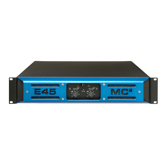
Summary of Contents for MC2 Audio E45
- Page 1 SERVICE MANUAL AUDIO Ltd., Units 6 & 7 Kingsgate, Heathpark Industrial Estate, HONITON, Devon EX14 1YG England Tel: ++(0)1404.44633 Fax: ++(0)1404.44660 www.mc2-audio.co.uk...
-
Page 2: Table Of Contents
CONTENTS PAGE INTRODUCTION MAINTENANCE CIRCUIT DESCRIPTION DIS-ASSEMBLY RE-ASSEMBLY ADJUSTMENTS/RE-ALIGNMENT APPENDICES: 1 EQUIPMENT REQUIRED SPECIFICATIONS and PRC CIRCUIT DIAGRAMS PCB710.x 701.x 712.x 703.x LAYOUT DIAGRAM PCB710/701/712... -
Page 3: Introduction
INTRODUCTION amplifier is designed for maximum reliability and minimum adjustment, as well as for top quality sonic performance. Re-alignment will only normally be necessary after parts replacement in the unlikely event of failure. There are four PCBs contained within the basic unit (plus cross-over filters if fitted): 1. - Page 4 * U101b (U201b) form an adjustable gain amplifier. The gain is set by a series of link positions. * The signal then passes to the output connector J105, (J205) PIN2 and is sent to the main amplifier on PCB710. * The signal is also passed to the limiter control circuit. * On Ch.
- Page 5 * The voltages from the sensors are logic 'OR'd' through D1, D2, D3 and D10 into latching comparator U1a, PIN4. This voltage also controls U2 to drive Q1a and Q1b, which supply the cooling fans. The fan speed is proportional to temperature. U1b forms an additional comparator to switch relays RLY2, RLY3 via CONN1 PIN4 (on PCB712) at approximately 90°C.
-
Page 6: Dis-Assembly
* T3, BR2, BR3, REG1, REG2 establish the low voltage rails +24V, ±15V. * Q3 circuit delays switching of RLY1 until the oscillator formed as part of U1 has started. * Drive signals for the IGBT switching transistors are from U1 PINS11 and 14 via isolator transformer T2. -
Page 7: Re-Assembly
b. MAIN PCB PCB710 * Remove PCB712 as in section d. * Remove PCB701 as above. * Remove connectors CON1 and 2 and all spade terminals (5). * Remove rear fan connectors (2). * Remove rear panel socket retaining screws 6 x PZ1. * Remove PCB retaining nuts and washers 5 x M4 (7.0mm socket), 2 x M3 pillars, 4 x PZ2 screws. -
Page 8: Adjustments/Re-Alignment
ADJUSTMENT/ALIGNMENT Normally no adjustment will be necessary after the ex-works alignment procedure. However, with time some drift of POT settings and component ageing may require some re-alignment to be made. After component replacement, re-alignment and testing to the original specifications should be carried out. -
Page 9: Appendices: 1 Equipment Required
Monitor Ch. B output and turn VR1 anti-clockwise until clipping just disappears. Measure and note the Ch. B O/P power. Monitor Ch. A output power. Apply the input signal to only Ch. A and adjust VR105 on PCB701 to match Ch. B in output power. NOTE THAT POWER MEASUREMENTS OF BOTH CHANNELS TOGETHER CAN ONLY BE MADE USING A BURST TONE IF A SINE WAVE SOURCE IS USED. -
Page 10: Specifications And Prc
APPENDIX 1 Equipment Required Repair: Pozi PZ1 and PZ2 driver 10mm SOCKET (front PCB only) SOCKET drive 7.0 mm SOCKET drive Re-alignment / re-test: 1. Signal Generator 10Hz to 40 kHz @ <0.001%THD (Burst tone for power measurements) 2. Audio analyser capable of measuring: dBu, Watts @ 4 ohms, THD% to 0.003% accuracy (Recommend: Audio Precision AP1 or similar.) 3. - Page 11 APPENDIX 2 Specification: Output power (Watts RMS) per channel 8 ohms @ 1kHz 1200 4 ohms @ 1kHz 2250 2 ohms @ 1kHz 3200 Mono Bridged 8 ohms @ 1kHz 4400 4 ohms @ 1kHz 6400 THD @ rated power 4 ohms 1 kHz <0.009% 20Hz-20 kHz...


Need help?
Do you have a question about the E45 and is the answer not in the manual?
Questions and answers