
Summary of Contents for AquaLusso Alto 50
- Page 1 INSTALLATION AND OPERATING MANUAL Alto 50 Steam Shower INSTALLERS PLEASE NOTE, THESE INSTRUCTIONS ARE TO BE LEFT WITH THE CUSTOMER Technical Support: 01422 410769...
- Page 2 Thank you for purchasing this product. To guarantee the product delivers a long service life, please ensure it is fi tted and used in accordance with the instructions contained in this booklet. Please check that the boxes contain all the items listed below, and report to us any parts that are missing or damaged prior to assembly and within 48 hours of receipt.
-
Page 3: Table Of Contents
Contents Product Contents List with Images Important Notice Before you Begin Assembly Fitting the Shower Valve Fitting a Seat (Optional) Leveling and Fitting the Tray Front Frame Assembly Installing Fixed Side Glass Panels Front Upright Pillar Front Corners Rear and Side Panels Central Tower Front Frame Installation Shower Ceiling... - Page 4 Alto Steam Shower Contents Below is a list of the parts you should have received for the installation of your shower. Please note that several parts may be pre-fi tted in place, such as the monsoon shower head, etc. Please note, the design and shape of parts may change occasionally but will always off er the same or greater functionality.
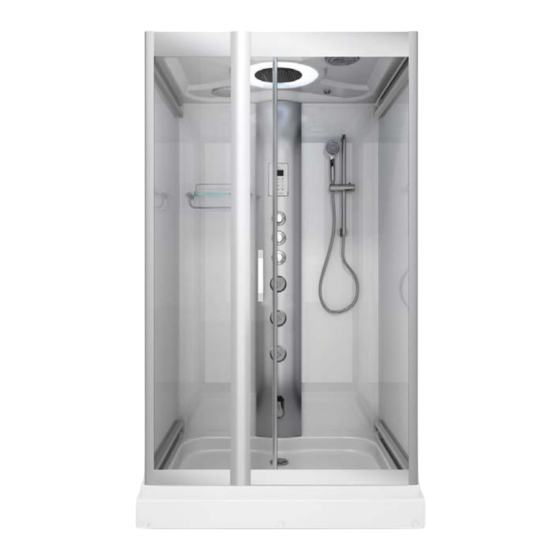
- Page 5 Tray/Base with Waste assembly and fl exible waste pipe pre-fi tted (shape and size vary according to model). Side Glass and framed panels (2). 24 x 16mm , 16 x 10mm, 4 x countersunk and 8 x 30mm screws Thermostatic shower valve and 2 braided hoses. Stainless Steel monsoon.
-
Page 6: Important Notice
IMPORTANT NOTICE Before you proceed with fi tting your Alto Shower please read and understand the following: By commencing testing and installation of the unit you are agreeing to the Terms and Conditions set out by us and copies are available by contacting us on the telephone (details on the cover of this manual). -
Page 7: Before You Begin
Before you begin Tools needed to assemble this shower cabin: Electric screwdriver with a selection of heads, regular screwdrivers, pipe grips, spanners, spirit level, sharp knife and rubber mallet. Connection of the electrical supply and plumbing may require additional tools. There is a drill bit supplied with the kit, to allow either widening of holes or drilling new holes which you feel cannot be located during construction. -
Page 8: Assembly
Assembly Do not fi t the shower into locations where you do not have at least 40cm access all around the cabin both for installation and for future service access. We advise you do to fi t sinks, toilets etc that restrict access behind the shower. -
Page 9: Fitting The Shower Valve
1. FITTING THE SHOWER VALVE The Thermostatic Shower Valve will need to be fi tted into the central tower panel into the three pre-drilled, vertical holesavailable for it. First remove the 3 Chrome Dials from the valve. The Selector Dial and ON/Off Dial are removed by unscrewing the Chrome Lug on the side. -
Page 10: Fitting A Seat (Optional)
2. FITTING SEAT (OPTIONAL) If your product came with a seat you may choose to install this item. Before commencing full assembly of the product you will need to prepare and fi t the seat. You need to drill three holes for the fi xing bolts into the tower at your preferred height. -
Page 11: Leveling And Fitting The Tray
3. LEVELING AND FITTING THE TRAY Remove the protective fi lm covering the base. Connect the soil pipe, trap and any couplings to the fl exible waste under the tub. You may choose to fi t either a HEPV0 trap with the appropriate couplings or choose to fi t a McAlpine ST28M coupling to a McAlpine 28-NRV trap. -
Page 12: Front Frame Assembly
4. FRONT FRAME ASSEMBLY Using the 8 x 30mm screws join the four sections The two identical UPPER and LOWER rails. These together as the digram below. The digram is have a fl at front face and running channels on the as viewed from the inside face of the frame, so rear faces. - Page 13 5. INSTALLING THE FIXED SIDE GLASS PANEL Locate the single, fl at clear glass section and the ‘U’ DO NOT HIT GLASS WITH HARD shaped door seals. OBJECTS TO PUSH INTO THE FRAME. From the front face of the frame section you assembled in the previous step, put one ‘U’...
-
Page 14: Front Upright Pillar
6. FRONT UPRIGHT PILLAR The front upright piece can be identifi ed by the On the inside of the upper and lower rails are two USB port located on its outer face in the upper holes. Using screws provided fi x the front upright part. -
Page 15: Front Corners
7. FRONT CORNERS Locate the front corner posts. These are long Fix the corner posts in position with the 10mm upright silver sections with an outer curved/corner screws - 4 on each post. face and two slots running the full length. Position each post over the left and right ends of the front frame assembly so that the other free slot on each faces backwards. -
Page 16: Rear And Side Panels
8. REAR AND SIDE PANELS Locate the two rear frames glass panels. These have a white frame and white glass. They will be marked for position LEFT and RIGHT. Locate also the two frames clear glass side walls. Take one side panel and one rear panel and position them along the back and sides of the tray. -
Page 17: Central Tower
9. CENTRAL TOWER Locate the central tower panel. This is the part with the control pad, shower valve and body jets. Ensure you REMOVE the rear white plastic housing covering the valve and pipes before installing as mentioned in the fi rst part of the installation. -
Page 18: Front Frame Installation
10. FRONT FRAME INSTALLATION The front door frame assembly can now be installed. The corner sections that were fi tted in section 7 have channels that enable the side walls to slide into. Off er up the front frame assembly and locate both side walls into the channels, then lower onto the tray in position. -
Page 19: Shower Ceiling
11. SHOWER CEILING Remove the protective fi lm from the roof/ceiling. If not already pre-fi tted, fi t the monsoon rain shower head into the centre of the roof. It is held in place with a retaining nut located on the outer/ upper face of the roof. -
Page 20: Temperature Sensor
13. FITTING THE SHOWER DOOR WHEEL RUNNERS The Alto 50 Steam Shower has a single sliding door. The door slides on door runner wheels. The shower door has two holes at the top and 2 holes at the bottom of the panel as well as two holes for a door handle midway on one edge. -
Page 21: Usb Connector
14. FITTING THE DOOR HANDLE The shower door requires a chrome fi nished door handle to be fi tted. The handle is comprised of several parts. Position the main handle part on the outside of a door ensuring the Chrome Washer and a Clear Washer are positioned also on the outside face over the thread. - Page 22 16. OVERHEAD/MONSOON SHOWER The overhead shower is fi tted into the ceiling from the inside. The overhead shower fi rst passes though the light diff user cover (inside the shower), so that the threaded end of the overhead shower passes out through the ceiling. Fit the FIXING NUT onto the threaded end on top of the ceiling to hold the shower and diff user cover securely in place.
-
Page 23: Hand Shower And Riser Installation
17. HAND SHOWER AND RISER You are now ready to assemble and connect the hand shower. The hand shower comprises of: Multi function hand shower ome nished riser bar Hand shower holster Chrome water hose Rear retaining nut Fitting screw The lower part of the riser bar has a threaded water connection. - Page 24 18. GLASS SHELF Assemble the shelf fully before fi tting into the shower. Position the lower chrome rail over the holes in the glass on the underside of the shelf with the silver grommets positioned between the two. On the upper side of the glass, pass the bolt through a washer and through the hole in the glass and fasten into the end of the lower rail.
- Page 25 19. SHOWER VALVE The shower valve can be accessed from the rear of the shower and is located on the central tower. The valve is divided into three parts that are joined together. The uppermost part is the divertor. There are three connections able to be made here.
- Page 26 20. SHOWER SEALS This shower comes with 1 fl apped shower seal that fi ts onto the trailing edge of the shower door. The seal is not designed to touch the glass fully so as to avoid squeaking, but will provide enough cover to stop water escaping around it.
-
Page 27: Water Connections
Water Connections This product requires a hot and cold water supply. Your Hot and Cold water supply pipes should ideally be fi nished about 1 meter above the fl oor centrally in the corner and fi nished with 15mm compression fi ttings. -
Page 30: Electrical Connections
Electrical Connections STEAM GENERATOR & ELECTRONIC CONTROL MAIN POWER UNIT This Steam Shower requires connections to MAINS This model has a separate Steam Generator ELECTRICITY. and Electronic Control Unit. Both parts have a Data Cable to provide electrical communication 1 x 13amp between each part and a Power transfer connection. -
Page 31: Sealing The Shower
Sealing the Shower We recommend that you seal the shower internally with a good quality bathroom sealant to provide an extra level of water proofi ng. After allowing the sealant to set (as per the sealant directions), water test the shower and check for signs of water leaking, please attend to them as required. -
Page 32: Final Testing
Final Testing Check and test that each outlet function (hand shower, body jets and monsoon) work as expected by rotating the DIVERTOR DIAL (top chrome dial). Check the ON/OFF dial enables the water to be fully on or off in the position indicated on the valve markings. -
Page 33: Valve Operation
Valve Operation There are 3 control dials inside your Shower Cabin. These dials control the output functions, water fl ow and temperature of your shower. The top dial can be turned to allow you to choose which output you wish to use: Body Jets, Overhead (Monsoon) Shower and Hand Shower. -
Page 34: Electronic Control Panel
Electronic Control Panel Your steam shower is fi tted with an electronic control panel that allows you to operate the electronic features of your shower. From the control panel you can control the lights, Steam, Radio, USB and Bluetooth audio. Power ON / OFF In standby mode this button is lit Red. -
Page 35: Bluetooth Pairing
Bluetooth Pairing Before you can start streaming Audio to your 5: After a small amount of time you should see shower you must fi rst establish a connection the device name of the shower appear “ SPROUT”. between the shower and the device that will Select this to complete the Pairing of the two stream the audio to the shower;... -
Page 36: Additional Information And Help
Steam Pod Where products are being used to infuse the steam in the steam pod, only products that are designed for such use should be used. The use of products not designed for infusing of steam may lead to damage to this product inducing but not exclusively, discoloration to the pod, tray base and or cabin walls. -
Page 37: Thermostatic Cartridge
Thermostatic Cartridge Your shower is fi tted with a Thermostatic Cartridge. Should you need to remove or replace the cartridge for maintenance or replacement, follow the instructions below. Q: I am having to turn the dial round as far as it will go to the hottest setting and the water is only just warm. - Page 38 With the Chrome dial removed you will see a plastic ring covering with the Thermostat underneath. Note down the position the ring is placed in. Pull the plastic ring (Temperature safety lock) towards you to remove. Keep this part safe You will now see the head of the Thermostat clearly visible.
- Page 39 FOR TECHNICAL ASSISTANCE PLEASE CALL 01422 410769...
Need help?
Do you have a question about the Alto 50 and is the answer not in the manual?
Questions and answers