Table of Contents
Advertisement
Quick Links
SPECIFICATIONS
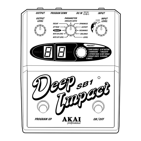
Functions: ......................... Programs: 9 memorized preset sounds: DARK BUBBLE, HARDCORE, KITAROH BASS, BRIGHT
Connectors: ...................... INPUT (Input impedance: 500k ohms or more)
Controls: ............................ INPUT LEVEL
Indicators: ......................... Input Level (LED x 3), Effect on/off (LED x 1), PROGRAM NO
Power requirements: ........ 9V DC/180mA, AC adaptor MP-9
Accessories: ..................... Operator's Manual, AC adaptor MP-9
Dimensions: ...................... 140 (W) x 175 (D) x 61 (H)mm
Weight: ............................... 750g
• Specifications are subject to change without notice.
Synth Bass Processor
MODEL
SYNTH, BRATS, FAT BOTTOM, MAJESTY, HOT SPACE, HICCUPS.
Program Up
Effect on/off
OUTPUT (Output impedance: 1k ohms or less)
DC IN (9 Volts)
PROGRAM DOWN for optional footswitch connection.
PARAMETER
DATA
OUTPUT LEVEL
FOOTSWITCH x 2 (unlatch type) ON/OFF and PROGRAM UP.
(7 segment LED x 1), DATA (7 segment LED x 1)
SERVICE MANUAL
DEEP IMPACT SB1
1
Advertisement
Table of Contents

Related Manuals for Akai DEEP IMPACT SB1


Summary of Contents for Akai DEEP IMPACT SB1
-
Page 1: Specifications
Synth Bass Processor DEEP IMPACT SB1 MODEL SPECIFICATIONS Functions: ......Programs: 9 memorized preset sounds: DARK BUBBLE, HARDCORE, KITAROH BASS, BRIGHT SYNTH, BRATS, FAT BOTTOM, MAJESTY, HOT SPACE, HICCUPS. Program Up Effect on/off Connectors: ...... INPUT (Input impedance: 500k ohms or more) -
Page 2: Safety Check After Servicing
# INFORMATIONS # SAFETY INSTRUCTIONS 1. Parts identified by the } symbol are critical for safety. SYMBOLS FOR PRIMARY DESTINATION Replace them only with the parts number specified. Unit destinations are indicated with letters as shown below. 2. In addition to safety, other parts and assemblies are Symbols Principal Destinations specified for conformance with such regulations as those... -
Page 3: Supplementary Information
SUPPLEMENTARY INFORMATION Points to be checked before making repairs In order to protect PROGRAM data, always be sure to make a memo of the PROGRAM data before making repairs. Caution: When the DATA knob is turned to change the PARAMETER on the SB1, the new data will automatically be memorized in the F-ROM, canceling the previous data value. - Page 4 PROGRAM NUMBER display DATA display PARAMETER Selector LED+5V. D405 LED+5V. D406 SA56-11SRWA SA56-11SRWA +9V. L8014A501C S1-1 R405 1.5K S2-1 R413 1.5K S1-2 R406 1.5K S2-2 R414 1.5K R302 R212 PC MODE VR OUTPUT LEVEL TR201 D+5V_3 S1-3 R407 1.5K S2-3 R415 1.5K VR351...
-
Page 7: How To Use This Parts List
PARTS LIST ATTENTION 1. When placing an order for parts, be sure to list the Part No., Model No. and the description of each part. Otherwise, the non-delivery of the part or the delivery of a wrong part may result. 2. - Page 8 4. PC FINAL ASSEMBLY BLK SB1 1. PC BOARD BLK SB1 Ref. No. Part No. Description Ref. No. Part No. Description SP-813027J PANEL MAIN SB1 BA-L8014A020A PC(#) SB1 BLK SB1 SE-813036J WIND SEGMENT PC(#) SB1 BLK CONSISTS OF FOLLOWING PC BOARDS SE-820327X SPACER SEGMENT •...
- Page 9 FINAL ASSEMBLY BLK SB1 SERVICE MANUAL...
- Page 10 ABBREVIATIONS FOR THE SERVICE MANUAL ABBREVIATION EXPLANATION ABBREVIATION EXPLANATION AMP (Amp) AMPlifier MINI MINImum Backet Brigade Diode MIXer Binary Code Decimal MODulation / MODulator B.DOWN Brake DOWN M.WHEEL Modulation WHEEL B.UP Back UP OSCillator Chip Enable Programmable Logic Device CHannel Random Access Memory COMP COMParator...
Need help?
Do you have a question about the DEEP IMPACT SB1 and is the answer not in the manual?
Questions and answers