Uponor Smatrix Base Installation And Operation Manual
Hide thumbs
Also See for Smatrix Base:
- Installation and operation manual (102 pages) ,
- Quick manual (224 pages) ,
- Quick manual (8 pages)

Related Manuals for Uponor Smatrix Base


Summary of Contents for Uponor Smatrix Base
- Page 1 Uponor Smatrix Base/Base PRO I N S TA L L AT I O N A N D O P E R AT I O N M A N U A L 11 | 2017...
-
Page 2: Table Of Contents
13.8 Factory reset ............96 6.11 Register thermostats in controller ......52 6.12 Register system devices ..........54 Operate Uponor Smatrix Base PRO interface ..97 14.1 Touch screen ............97 Install Uponor Smatrix Base timer .....56 14.2 Home screen ............97 Placement of timer ..........56 14.3... - Page 3 Maintenance .............112 15.1 Manual preventive maintenance ......112 15.2 Automatic preventive maintenance ......112 15.3 Corrective maintenance ........112 15.4 Controller LEDs.............113 15.5 Restore from backup (Base PRO only) ....114 Troubleshooting ..........115 16.1 Troubleshooting after installation ......117 16.2 Digital thermostats T-146, T-148 and T-149 alarms/problems ...........117 16.3 Analogue thermostat T-143 alarms/problems ..118...
-
Page 4: Copyright And Disclaimer
Modification or use of any of the contents of the The manual is provided “as is” without warranties of manual for any other purpose is a violation of Uponor’s any kind, either expressed or implied. The information copyright, trademark and other proprietary rights. -
Page 5: Dk 2 Preface
Uponor cannot accept any responsibility for damage or breakdown that can result from ignoring these instructions. Power arning The Uponor system uses 50 Hz, 230 V AC power. In case of emergency, immediately disconnect the power. Technical constraints aution To avoid interference, keep installation/data cables away from power cables of more than 50 V. -
Page 6: Uponor Smatrix Base/Base Pro
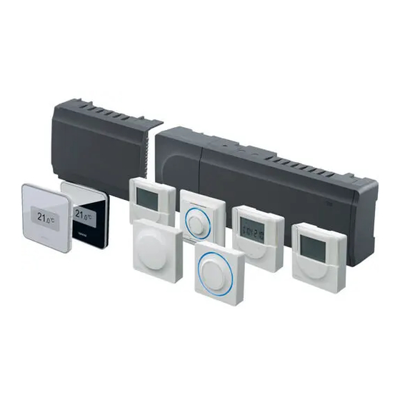
System overview Uponor Smatrix Base/Base PRO consists of a controller, thermostats, actuators and an optional timer. The controller manages the operation of the actuators when the thermostats detect a demand for heating or cooling. -
Page 7: Example Of A System
Example of a system Item Description The illustration below shows Uponor Smatrix Base PRO Uponor Smatrix Base PRO Interface I-147 (interface I-147) with several installation options and thermostats. Uponor Smatrix Base Thermostat Prog.+RH T-148 (digital thermostat T-148) Uponor Smatrix Base Thermostat D+RH Style T-149... -
Page 8: Uponor Smatrix Base/Base Pro Components
Uponor Smatrix Base/Base PRO components Pos. Uponor designation Description Pos. Uponor designation Description Uponor Smatrix Transformer module Uponor Smatrix Base Programmable digital Transformer A-1XX Thermostat Prog.+RH thermostat with (transformer A-1XX) T-148 relative humidity sensor Uponor Smatrix Base Controller Uponor Smatrix Base... - Page 9 Integrated heat pump module (only available in systems with four controllers or less, and in selected countries, contact a local Uponor office for more information). U P O N O R S M AT R I X B A S E / B A S E P R O · I N S TA L L AT I O N A N D O P E R AT I O N M A N U A L...
- Page 10 Uponor Smatrix Base Controller X-145 Components of the controller Main characteristics: The illustration below shows the controller and its components. • Integrated Dynamic Energy Management functions such as autobalancing (on by default). • Electronic control of actuators. • Connection of maximum eight actuators (24 V).
- Page 11 Diagnostic function detecting if a room thermostat nterfaCe only is installed in the right room (room check). The Uponor Smatrix Base PRO Interface I-147 is a touch function is only available in systems with four screen interface which communicate with the X-147 controllers or less.
- Page 12 The thermostat shows the ambient, set temperature or individually or in combination with each other. relative humidity on the display. Temperature settings are adjusted using the +/- buttons on the front. The following Uponor Smatrix thermostats can be used in the system: Main characteristics: •...
- Page 13 Uponor Smatrix Base Thermostat Prog.+RH T-148 • Cannot be overridden by other thermostats or timers, when it is set to a program. The thermostat shows the ambient, set temperature or relative humidity, and time on the display. Settings • Relative humidity limit indicated in display.
- Page 14 Uponor Smatrix Base Thermostat Dig T-146 Uponor Smatrix Base Thermostat Standard T-145 The thermostat shows the ambient or set temperature The thermostat temperature settings are adjusted using on the display. Temperature settings are adjusted using the dial. The 21 °C position is marked on the dial.
- Page 15 Uponor Smatrix Base Thermostat Flush T-144 Uponor Smatrix Base Thermostat Public T-143 The thermostat temperature settings are adjusted using The thermostat is designed for public locations which the dial. The 21°C position is marked on the dial. means that the dial is hidden. It must be removed from the wall to set the temperature.
- Page 16 Uponor Smatrix Base PRO Room Sensor+RH Style imer T-141 Uponor Smatrix Base Timer I-143 (Base only) The thermostat is designed to be as small as possible, The timer enables control of the system with and still able to control the room temperature.
- Page 17 Uponor Smatrix Base Star Module M-141 The slave module adds six channels and actuator The star module enables thermostats to be installed in outputs to an existing Uponor Smatrix Base controller. a centralized star topology instead of the standard bus topology.
- Page 18 (PWM) signals. The KNX module enables communication between an Uponor Smatrix Base PRO system and a standard KNX On/off control bus. When installing a system with on/off control, manual Main characteristics: balancing of the system is required.
-
Page 19: Accessories
Accessories Functions Uponor offers a wide variety of accessories for use with Uponor Smatrix Base/Base PRO is used to control an the standard portfolio. underfloor heating and/or cooling system in a house or building. The thermostats registered to the controller is used to control the actuators mounted on top of the manifold valves. - Page 20 (set in the interface, default usage patterns, removing the need of manual balancing. 75%). If a dehumidifier is installed (requires an Uponor This gives more even floor temperatures and faster Smatrix Move PRO controller) it will be activated when system reaction times with lower energy consumption the dehumidifier start limit is reached.
- Page 21 H/C-switch (Base PRO with interface only): iCro Card only Uponor Smatrix Base PRO uses a microSD card for Use the relay as a heating/cooling output. A circulation cloning (interface settings), automatic backup (settings pump cannot be connected to the controller using the and thermostat registration data), manual restoration PUMP connector.
-
Page 22: Fi 4 Install Uponor Smatrix Base/Base Pro
Stage Procedure Page Placement of interface Startup guide To determine where to best place the Uponor Smatrix Base components, follow these guidelines: • Ensure that the controller can be installed close to the manifold pair. Note that each manifold pair must have its own controller. -
Page 23: Installation Example
Only 24 V Uponor actuators are compatible outputs (slave module M-140) and extra bus connectors (slave with the controller. module M-140 and star module M-141) to the Uponor Smatrix Base controller See also the wiring diagram in the end of the manual. - Page 24 PRO Controller (six channels) with an optional Uponor system and individual settings for each thermostat Smatrix Base Slave Module (six extra channels) using can be set. Schedules can be programmed for one system devices (S) and thermostats (T) as shown in or several thermostats instructing them when to figure.
- Page 25 Digital thermostats T-146, and T-149: This requires one or more of the following: • Set the ECO setback value in menu 03 to 0. • Uponor Smatrix Base PRO Interface I-147 (Base Digital thermostat T-148: PRO only) The interface allows individual programmed •...
-
Page 26: Install Uponor Smatrix Base/Base Pro Controller
Install Uponor Smatrix Base/Base PRO controller Placement of controller Attaching/detaching components The components can either snap on or off without the Refer to the installation preparation guidelines (see need of removing the covers (A, recommended to do on section 4.2 Prepare for installation), and use the... -
Page 27: Attach Controller To The Wall
Attach controller to the wall CreWs and Wall Plugs The figure below shows controller mounting hole The controller is delivered in kits including screws, wall positions and how to attach it to the wall using screws plugs and a DIN rail. and wall plugs. -
Page 28: Connect The Star Module (Optional)
N O T E ! Only one star module extension per bus type (thermostat and/or system bus) is supported per Uponor Smatrix Base PRO controller. A star module can only be used for one bus type at a time. That is, a thermostat cannot be connected to a star module connected to the system bus and vice versa. - Page 29 aBle ConneCtion emove the star module The illustration below shows how to connect the star The illustration below shows how to remove the star module to the controller using cable connection. module from the controller. 1 . 2 N O T E ! This connection method uses two extra connection points in the system.
-
Page 30: Connect Components To Controller
Quick connectors for actuators must be connected to. Bus connection terminals System bus connection terminals (Base PRO only) Power LED Uponor Smatrix Base Slave Module M-140 (optional) LEDs for channels 07 – 12 Uponor Smatrix Base Star Module M-141 (optional) - Page 31 Make sure the controller is connected to a system bus connector (one of the rightmost See section 6 Uponor Smatrix Base/Base PRO connectors) on the controller. Otherwise the thermostats and sensors for installation of thermostats. controllers will be unable to communicate with each other.
- Page 32 • Use an input: Connect the input to the controller. Switch mode using a switch on the wall or a heat pump. Uponor Smatrix Base PRO system: • Use an input: Connect the input to either the controller. Switch mode using a switch on the wall or a heat pump.
- Page 33 Cooling available. 4 = Off. See section 6.4 Connect external sensor 7. Enter the submenu Operating mode to the to thermostat > Uponor Smatrix Base Thermostat settings menu to Heating/cooling and select H/C Public T-143 for more information. Slave.
- Page 34 To connect a heating/cooling output to a sub N O T E ! controller (Base PRO with interface only): This connection requires a dry contact sensing input in the component producing The illustration below shows components of the heating/cooling. heating/cooling system connected to a sub controller. 1.
- Page 35 N O T E ! PUMP See the documentation from the circulation pump supplier as well as relevant Uponor wiring diagrams before connecting the pump. • The controller cannot supply power for the pump.
- Page 36 Shared or individual pumps (Base PRO with onneCt Boiler oPtional interface only) The controller includes a boiler relay, it can be used to send a signal to either fire the heat source or to power A pump for all manifolds and controllers can be open a 2-port motorised zone valve positioned on the connected to the closest controller.
- Page 37 onneC t he at PumP integr ation oP tional arning a se only Electrical installation and service behind The controller can connect to selected heat pumps and secured 230 V AC covers must be carried adjust the supply temperature to the system. out under the supervision of a qualified electrician.
-
Page 38: Connect The Controller To Ac Power
See the heat pump supplier documentation and the relevant Uponor wiring diagram before performing the connection. Contact a local Uponor office for complete list of compatible heat pumps. To connect a compatible heat pump to the controller: 1. Study the wiring diagram in the end of the manual, or inside the cover of the controller, to locate the connector positions. -
Page 39: Test Actuators
Test actuators To test the actuators: 1. Enter forced mode by pressing the > button while in It is possible to manually open or close an actuator run mode. connected to a channel when testing the system. For information about how to exit to run mode, see Testing an actuator takes about 10 minutes and the section 10.4 Run mode >... -
Page 40: Install Uponor Smatrix Base/Base Pro
Label thermostats system: Label the thermostats, where suitable, with the channel • Uponor Smatrix Base Thermostat D+RH Style T-149 numbers they are to control, for example, #02, #03. • Uponor Smatrix Base Thermostat Prog.+RH T-148 For a system with interface and several controllers, add the ID of each controller, for example, 1.02, 1.03, 2.02,... - Page 41 ireCt ConneCtion to Controller and slave onneCt CommuniCation CaBle to Controller module or slave module Every thermostat in the example is connected to the controller and slave module (if available) with its own cable. onneCtion to attaChed star module The star module is attached to the controller and slave module (if available) adding extra connection terminals to the system.
- Page 42 onneCt CaBle to star module onneCt CommuniCation CaBle to thermostat t-149 To connect a communication cable to thermostat T-149: To connect a communication cable to a star module: 1. Press the push button on the connection terminal 1. Lead the cables through cable entries in the star on the back of the thermostat.
- Page 43 onneCt CommuniCation CaBle to thermostat onneCt CommuniCation CaBle to thermostat t-143, t-145, t-146, t-148 t-144 A B + - A B + - To connect a communication cable to thermostat T-148, To connect a communication cable to thermostat T-144: T-146, T-145 and T-143: 1.
-
Page 44: Connect External Sensor To Thermostat (Optional)
Connect external sensor to onneCt CommuniCation CaBle to thermostat t-141 thermostat (optional) An optional external sensor can be connected to the thermostats (except the standard thermostat T-145, flush thermostat T-144, and room sensor T-141) for extra functionality. N O T E ! For accurate temperature: attach the outdoor sensor to the north side of the building where it is unlikely to be exposed to direct sunlight. - Page 45 Use the software on the thermostat to select a control mode which corresponds to the use of the sensor and thermostat. See section 12 Operate Uponor Smatrix Base/Base PRO digital thermostats for more information. .+rh Ponor...
- Page 46 Ponor matriX hermostat uBliC Switch Function* t-143 Standard room thermostat ON DIP The external temperature sensor input can be used 1 2 3 4 for either a floor temperature sensor, an outdoor temperature sensor, or a Comfort/ECO switch. Use Standard room thermostat together with a ON DIP floor temperature sensor the DIP switches on the thermostat to select a control...
-
Page 47: Attach Thermostat T-149 To The Wall
Attach thermostat T-149 to the sing Wall BraCKet and surfaCe adaPtor wall oPtion The illustration below shows thermostat mounting hole The thermostats are delivered in kits including screws, positions and how to attach it to the wall using a wall wall plugs, and a wall bracket, presenting several bracket and surface adaptor (option). -
Page 48: Attach Thermostat T-148, T-146, T-145, And T-143 To The Wall
Attach thermostat T-148, T-146, Attach thermostat T-141 to the T-145, and T-143 to the wall wall The thermostats are delivered in kits including screws, The thermostats are delivered in kits including screws, wall plugs, and a wall bracket, presenting several wall plugs, and a wall bracket, presenting several options of attaching the thermostat to the wall. -
Page 49: Attach Thermostat T-144 To The Wall
Attach thermostat T-144 to the sing Wall BraCKet and surfaCe adaPtor wall oPtion The illustration below shows thermostat mounting hole The illustration below shows mounting hole positions on positions and how to attach it to the wall using a wall the wall bracket, and how to attach the thermostat. -
Page 50: First Startup Of Digital Thermostats
This setting is required to utilise scheduling See section 12 Operate Uponor Smatrix Base/Base PRO programs for this thermostat. digital thermostats for more information. -
Page 51: First Setup Of Digital Thermostats
3. Set 12 h or 24 h display of time. 6.10 First setup of digital thermostats eleCt thermostat Control mode If an external sensor is connected to the thermostat, a control mode must be selected to accommodate the extra functionality of the sensor. 4. -
Page 52: Register Thermostats In Controller
6.11 Register thermostats in controller emPerature setPoint The thermostats are delivered with a default setpoint of 21 °C. egistration at first startuP When starting the controller for the first time, it The illustration below shows how to adjust the automatically enters run mode, which is the standard thermostat temperature setpoint. - Page 53 To register room thermostats in the controller: T-149 1. Press and hold the OK button on the controller until the LED for channel 1 (or the first unregistered channel) flashes red. T-146 T-148 2. Use buttons < or > to move the pointer (LED flashes red) to a preferred channel.
-
Page 54: Register System Devices
The selected channel LED in the controller turns fixed green and the registration is complete. • Touch screen interface (Base PRO only), see section 8 Install Uponor Smatrix Base PRO interface for THERMOSTAT T-149 installation procedure 5.1 Press and hold both buttons on the •... - Page 55 1 = Touch screen interface (Base PRO only) See section 8 Install Uponor Smatrix Base PRO interface for more information. 1 = Timer See section 7 Install Uponor Smatrix Base timer for more information. 2 = Not used 3 = Public thermostat with outdoor sensor...
-
Page 56: Install Uponor Smatrix Base Timer
N O T E ! Only one timer per controller can be registered. N O T E ! A timer can only be registered to a Uponor Smatrix Base controller. Placement of timer Refer to the installation preparation guidelines, see section 4.2 Prepare for installation. -
Page 57: Attach A Timer To The Wall
Attach a timer to the wall onneC t CommuniC ation C aBle to thermostat The timer is delivered in kits including screws, wall plugs, and a wall bracket, presenting several options of attaching the timer to the wall. sing Wall BraCKet reCommended A B + - The illustration below shows timer mounting hole... -
Page 58: First Startup Of The Timer
2. Set minutes. When starting the timer for the first time, before registering, the timer requires some basic settings. See section 13 Operate Uponor Smatrix Base timer for more information. 3. Set 12 h or 24 h display of time. -
Page 59: Register Timer In Controller
Register timer in controller aution Make sure the controller is in run mode. The illustration below shows how to register a timer For information about how to exit to run associated with the controller. mode, see section 10.4 Run mode > Exit to run mode. -
Page 60: Install Uponor Smatrix Base Pro Interface
Install Uponor Smatrix Base PRO interface The following interfaces can be connected to the Connect interface to the controller system: The interface is connected to the (or one of the) • Uponor Smatrix Base PRO Interface I-147 controllers using daisy chain, direct connection, or using Up to 16 controllers can be registered and controlled by star topology (the star module can be used). - Page 61 onneCt CommuniC ation C aBle to Controller onneCt CommuniCation CaBle to interfaCe Wall BraCKet To connect a communication cable to the wall bracket: 1. Lead the cables through the wall socket. 2. Insert two wires (A,B), the - wire is optional and only used in some cases, into the connectors on the wall bracket.
-
Page 62: Attach The Interface To The Wall
Attach the interface to the wall Startup guide When starting the interface for the first time, or after using Wall BraCKet reCommended a factory reset, a startup guide is shown in the touch The illustration below shows mounting hole positions on screen display. - Page 63 Appears in some menus where more specific 2. Confirm and continue to the next step in the startup settings are available for a parameter guide. See section 14 Operate Uponor Smatrix Base PRO Regional set. interface for more information. Time format: AM/PM 3.
- Page 64 et date and time egister the interfaCe to a Controller Set the date and time of the system. The interface must be registered to a controller to be able to control the connected system. Date & Time Date: 01/01/2014 Up to 16 controllers can be registered and controlled by the interface.
- Page 65 N O T E ! Registration of at least one thermostat must be done before registering an interface. N O T E ! Registration of at least one thermostat must be done before registering an interface. aution Make sure the controller is in run mode. For information about how to exit to run mode, see section 10.4 Run mode >...
-
Page 66: Finishing Installation
Finishing installation Make a complete check up of the installation: 1. Check that the thermostats are working correctly. Turn thermostat setpoints to maximum to obtain a heating demand and make sure that the actuators are running. 2. Set thermostats and interface (if installed, Base PRO only) to the defined operating settings. -
Page 67: Operate Uponor Smatrix Base/Base Pro Controller
10 Operate Uponor Smatrix Base/Base PRO controller Uponor Smatrix Base/Base PRO controls the underfloor 10.3 Operation with scheduling heating/cooling installation according to customer programs needs. Temperatures are adjusted with thermostats Scheduling programs provide an option to switch located in each room. -
Page 68: Reset The Controller
10.5 Reset the controller To unregister a channel: 1. Press and hold the OK button on the controller until If problems, such as inaccurate channel registration the LED for channel 1 flashes red/green, or the first exist, reset the controller. The following illustration unregistered channel flashes red. -
Page 69: Update Controller Software (Base Pro Only)
Make sure the controller is in run mode. Software and update instructions can be found on the For information about how to exit to run Uponor website. mode, see section 10.4 Run mode > Exit to run mode. U P O N O R S M AT R I X B A S E / B A S E P R O · I N S TA L L AT I O N A N D O P E R AT I O N M A N U A L... -
Page 70: Operate Uponor Smatrix Base/Base Pro Analogue Thermostats
11 Operate Uponor Smatrix Base/Base PRO analogue thermostats Two types of thermostats, both analogue and digital, 11.1 Thermostat layout can be used in an Uponor Smatrix Base/Base PRO system. t-141 oom sensor thermostat During normal operation the thermostat is monitored Analogue thermostats: and controlled via the Base PRO interface I-147. - Page 71 t-143 t-144 uBliC thermostat lush thermostat During normal operation a discreet LED on back of The illustration below shows the parts of the the thermostat is lit for about 60 seconds if there is a thermostat. demand for heating or cooling. The thermostat contains a switch that, if activated during registration, sends an alarm when the thermostat is removed from the wall.
-
Page 72: Adjust Temperature
t-145 11.2 Adjust temperature tandard thermostat During normal operation a discreet LED on the The temperature is changed by adjusting the setpoint thermostat is lit for about 60 seconds if there is a on the thermostat to a value between 5 and 35 ˚C. demand for heating or cooling. -
Page 73: Disable Timer Function
t-144 11.3 Disable timer function hermostat flush Use the dial on the thermostat to adjust the Thermostats T-143, T-144, and T-145 have switches temperature. A LED will light up when twisting the dial. allowing the user to disable the timer function (Comfort It shuts off after about 10 seconds of inactivity. -
Page 74: Factory Reset
11.4 Factory reset To factory reset the thermostat: 1. Remove the thermostat from the wall. Factory reset sets all parameter values to default settings. 2. Disconnect the controller from the power supply. N O T E ! 3. Press and hold the registration button on the Do not factory reset the thermostat if not thermostat while reconnecting the controller to power again. -
Page 75: Operate Uponor Smatrix Base/Base Pro Digital Thermostats
12 Operate Uponor Smatrix Base/Base PRO digital thermostats Two types of thermostats, both analogue and digital, t-146 t-148 hermostats can be used in an Uponor Smatrix Base/Base PRO T-146 system. T-148 The digital thermostats have a display relaying information to the user and buttons for control. -
Page 76: Display Layout
12.2 Display layout Change setpoint t-149 hermostat The figures shows different display screens and the different symbols that can be shown. Run mode (default screen) Pos. Icon Description Change setpoint mode Temperature setpoint, using a - or + sign, two digital characters, a decimal point and a character showing either Pos. - Page 77 Alarms Control mode Pos. Icon Description Pos. Icon Description Alarm mode Current control mode Faulty indoor temperature sensor Indoor temperature indicator Current control mode Faulty floor temperature sensor Indoor temperature with floor temperature limitation indicator Current control mode Faulty remote temperature sensor Remote sensor temperature indicator Current control mode Faulty outdoor temperature sensor...
- Page 78 elative humidity Pos. Icon Description T-146 only Message field using three alphanumerical characters T-146 Temperature reading using a - or + sign, two digital characters, a decimal point T-148 and a character showing either 0 or 5 Pos. Icon Description Relative humidity level T-148 Relative humidity reading using two...
-
Page 79: Operating Buttons
12.3 Operating buttons Pos. Icon Description The figure below shows buttons used to operate the Settings menu digital thermostats. T-149 Settings menu number Heating demand Cooling demand Comfort mode ECO mode Flashing icon in thermostat T-146 indicates activated holiday mode in the system. -
Page 80: Start Up
12.4 Start up (t-148 et time and date only When starting the thermostat for the first time, or after When starting up, the software version is shown in the a factory reset, the software requires the time and date display for about three seconds. Then the thermostat to be set. -
Page 81: Adjust Temperature
4. Set day of the week (1 = Monday, 7 = Sunday). 12.5 Adjust temperature The temperature is changed by adjusting the setpoint on the thermostat. Use the buttons on the thermostat to adjust the temperature. The display will light up when pushing a button. -
Page 82: Run Mode
12.6 Run mode rt, r oom temPerature mode 1. Room temperature (default) During normal operation the thermostat is in run mode. 2. Alarm list (only shown if an alarm is present in a While in run mode the display shows specific control T-149 thermostat) mode information. -
Page 83: Change Control Mode
12.8 Change control mode 12.9 Settings If an external sensor is connected to the thermostat, a In this menu all settings regarding the operation of the control mode must be chosen to accommodate the extra thermostat is set. functionality of the sensor. N O T E ! N O T E ! As long as scheduling (program 00) is... - Page 84 00 P (t-148 Program P3: rogram only In this menu, one of seven different scheduling programs for Comfort/ECO mode can be set. Program 1 to 6 is pre-programmed and the 7th is user defined. The scheduled programs show the day split into 30 minute intervals which is set to either Comfort (black marker) or ECO mode (blank marker).
- Page 85 Select scheduling program Customise user defined program for a full week To select a scheduling program: NOTE! This method resets the current user defined program to factory defaults. 1. Press OK to enter parameter edit mode. To customise the user defined program: 2.
- Page 86 02 h 04 C eating Cooling Changeover ontrol mode This menu is not visible if the thermostat is registered In this menu control mode for the thermostat is set. to a controller. Heating/cooling changeover will be If an external sensor is connected to the thermostat, a controlled by a physical heating/cooling switch (Base control mode must be chosen to accommodate the extra or Base PRO) or the interface (Base PRO only), if...
- Page 87 06 l 08 d oW floor temPerature limitation isPlay unit In this menu a limit on the minimum allowable floor In this menu temperature display unit is set. temperature is set. To change this setting: This menu is only visible if control mode RFT is activated 1.
-
Page 88: Factory Reset
11 r t-149 oom temPerature CaliBration hermostat In this menu the room temperature shown in the thermostat display can be calibrated. To change this setting: 1. Press OK to enter parameter edit mode. 2. Use buttons - or + (T-149 = or ) to change the parameter. -
Page 89: Operate Uponor Smatrix Base Timer
13 Operate Uponor Smatrix Base timer The timer (Base only) provide an option to switch 13.2 Screen layout selected rooms between Comfort and ECO mode using The figure below shows all possible symbols and a 7-day program. It has a display relaying information to characters that can be shown on the display: the user and buttons for control. -
Page 90: Operating Buttons
13.3 Operating buttons Pos. Icon Description The figure below shows buttons used to operate the timer. Digital clock Parameter name in settings menu Indicator showing AM or PM when the thermostat is set to 12 h mode No indication when the thermostat is set to 24 h mode Weekday selected/activated 1 = Monday... -
Page 91: Start Up
13.4 Start up 3. Set 12 h or 24 h display of time. When starting up, the software version is shown in the display for about 3 seconds. Then the timer enters run mode. The first time the timer is started, or after a factory reset, the software requires the time and date to be set. -
Page 92: Run Mode
13.5 Run mode 13.7 Settings The timer can show the following information in the In this menu all settings regarding the operation of the display. timer is set. • Clock N O T E ! If no button is pressed for about 8 seconds, •... - Page 93 00 P Program P4: rogram In this menu, one of seven different scheduling programs for Comfort/ECO mode can be set. Program 1 to 6 is pre-programmed and the 7th is user defined. The scheduled programs show the day split into 30 minute intervals which is set to either Comfort (black marker) or ECO mode (blank marker).
- Page 94 Select scheduling program Customise user defined program for a full week To select a scheduling program: NOTE! This method resets the current user defined program to factory defaults. 1. Press OK to enter parameter edit mode. To customise the user defined program: 2.
- Page 95 01 h 03 eCo oliday mode mode setBaCK temPerature In this menu a time period can be set well in advance In this menu the ECO mode setback temperature for the for when away on holiday. When activated, the timer analogue thermostats is set.
-
Page 96: Factory Reset
10 t 13.8 Factory reset ime and date In this menu time and date is set. This setting is required Factory reset sets all parameter values to default to utilise scheduling programs in this timer. settings. Use buttons - or + to change the value. Press the OK N O T E ! button to set the value and move to the next editable Do not factory reset the timer if not... -
Page 97: Operate Uponor Smatrix Base Pro Interface
14 Operate Uponor Smatrix Base PRO interface The interface provides a centralised management of 14.2 Home screen the Uponor Smatrix Base PRO system with continuous The home screen is the base of the menu system in information updates and access to system settings. -
Page 98: Navigating The Menu System
14.3 Navigating the menu system Con grid The top most menu use icons for navigation. Press an The menu system is navigated by the touch screen and icon to enter a submenu to change specific settings. is put together with a basic set of menu types. General navigation buttons Icon Description... -
Page 99: Adjust Temperature
14.4 Adjust temperature et Parameter Use the arrow buttons, < and >, to move the marker With the interface the room temperature of every room between characters and use buttons - or + to change in the system can be monitored and adjusted. the previously set value. -
Page 100: Room Information
14.5 Room information Pos. Description ECO mode activated In this menu the setpoint for every room can be adjusted without the need to be at the affected Scheduling activated, number indicates which thermostat. program Setpoint temperature Advanced information and settings are available in The background colour changes if the system is in submenus. - Page 101 ECO setback oom status This menu shows advanced information not available in Default: 4.0 ˚C the room information menu. It is accessible by pressing Setting range: 0.0 – 11.0 ˚C, 0.5 ˚C increments button H in the room information menu. Set the setback temperature for when entering ECO Information shown in the menu: mode in a room.
-
Page 102: Main Menu
Comfort setting 14.6 Main menu Default: 0% (Off) The main menu is the top most menu and it uses icons Setting range: Inactive, 5 – 12%, 1% increments for navigation. Press an icon to enter a submenu to Set basic level of comfort for the room when there is change specific settings. -
Page 103: System Settings
14.7 System settings oom CheCK This menu is only available to Base PRO systems with In this menu, system specific settings can be changed. less than 5 controllers. This is a diagnostic function detecting whether a room eneral setBaCK Default: 4.0 ˚C thermostat is installed in the right room. -
Page 104: Holiday
rh C 14.8 Holiday ontrol General RH setpoint: When away on holiday, the system can be programmed Default: 75% in advance to reduce the system energy need by Setting range: 0 – 100%, 1% increments adjusting the setpoint while away. Deadzone (hysteresis): Default: 5% Set Enable Holiday mode to Yes to enable holiday... -
Page 105: Heating/Cooling
14.9 Heating/Cooling 14.10 Integration In this menu, settings regarding switching between This menu manages settings when integrating the heating and cooling are made. system with other devices. First select if cooling is available in the system. When ontroller relay answering Yes a settings menu appears. In the settings Default: Common pump (Base PRO), Individual pump (Base) menu ( ) Cooling offset and Operating mode can Setting range: Common pump, Individual pump... -
Page 106: Trends
Setting range: Active, Inactive This function is only available in selected countries, Activate if a supply water controller is connected to the contact a local Uponor office for more information. Base PRO system. aution See separate documentation for more information. -
Page 107: System Info
14.12 System info Screen lock: Default: Inactive This menu shows information about current software Setting range: Active, Inactive versions, the number of controllers connected and other This function requires a microSD card when being interface specific information. activated. It can be removed afterwards if needed 14.13 Preferences without affecting the function or PIN-code. -
Page 108: Alarms
14.14 Alarms 14.15 ECO profiles (scheduling) This menu shows a list of current alarms in the system. Set, change or view current ECO profile schedules for the current room or system. The list contains information about which kind of alarm it is (Type), where it is (Rooms) and when it occurred N O T E ! (Time). - Page 109 Ctivate a Programmed sChedule Pos. Description To select an ECO profile: Weekdays, press one of the days to show or modify the schedule for that day 1. Go to the ECO profile menu. Weekday not yet programmed (Modify only) 1.1 For a single room: Weekday selected for viewing or programming Home screen >...
-
Page 110: Microsd Card
> ECO profile. To update the software in the interface: 2. Use buttons < and > [H and K] to select the 1. Download the software package from the Uponor Custom profile. The profile name is displayed at website. -
Page 111: Factory Reset Of The Interface
rite Cloned settings dd disPlay languages To add a new display language: aution Do not remove the microSD card while writing 1. Insert a microSD card, containing the language cloned settings. packages (supplied with the interface), into the interface. To write cloned settings to the microSD card: 2. -
Page 112: Maintenance
If the system includes an Uponor Smatrix Base PRO Do not use any detergents to clean the interface, the exercise function can be used at any time. Uponor Smatrix Base components. -
Page 113: Controller Leds
15.4 Controller LEDs The table below describes the status of the controller LEDs. If no Uponor Smatrix Base PRO interface is connected to the system, it is recommended to occasionally check Status the power LED on the controller for alarms. The power... -
Page 114: Restore From Backup (Base Pro Only)
15.5 Restore from backup (Base PRO 1 3 4 only) If an existing Uponor Smatrix Base PRO controller has been replaced, installation data (including thermostat registration data) from the replaced controller can be reused to setup the new controller. aution Make sure the controller is powered off before ejecting the microSD card. -
Page 115: Troubleshooting
In case of mixed up thermostats in a Uponor Smatrix Base PRO system, use the room check function, see section 14.7 System settings for more information. - Page 116 Problem Indication Probable cause Solutions The room is too Corresponding loop is warm even after a An actuator does not close Contact the installer warm long period without heat call Check that the actuator is correctly (or too cold in installed cooling mode) Replace the actuator...
-
Page 117: Troubleshooting After Installation
16.1 Troubleshooting after installation Problem Indication Probable cause Solutions The system does The power indicator in the controller is off There is no AC power to the controller 1. Check that the controller is connected not start to AC power 2. -
Page 118: Analogue Thermostat T-143 Alarms/Problems
The table below shows problems that can occur in the digital thermostat T-149. Indication Probable cause Solutions Alarm icon is displayed An error has occured Go to the alarm list for more information The display is off The cable is not connected or a wire is Check the wiring damaged. -
Page 119: Technical Data
17 Technical data 17.1 Technical data General IP20 (IP: degree of inaccessibility to active parts of the product and degree of water) Max. ambient RH (relative humidity) 85% at 20 °C Thermostat and timer CE marking ERP (thermostat only) Low voltage tests EN 60730-1* and EN 60730-2-9*** EMC (electromagnetic compatibility requirements) tests EN 60730-1... -
Page 120: Technical Specifications
Controller CE marking Base: IV Base PRO: VIII Low voltage tests EN 60730-1* and EN 60730-2-1** EMC (electromagnetic compatibility requirements) tests EN 60730-1 Power supply 230 V AC +10/-15%, 50 Hz or 60 Hz Internal fuse F3.15AL 250 V, 5x20 3.15A quick acting Internal fuse, Heat pump output TR5-T 8.5 mm Wickmann 100 mA Time lag Operating temperature... -
Page 121: Controller Layout
Quick connectors for actuators Bus connection terminals System bus connection terminals (Base PRO only) Power LED Uponor Smatrix Base Slave Module M-140 (optional slave module) LEDs for channels 07 – 12 Uponor Smatrix Base Star Module M-141 (optional star module) End cap MicroSD card (Base PRO only) 17.4 Wiring diagrams... - Page 122 Ponor matriX ase Controller A B + - A B + - A B + - lave module A B + - A B + - A B + - tar module U P O N O R S M AT R I X B A S E / B A S E P R O · I N S TA L L AT I O N A N D O P E R AT I O N M A N U A L 1 2 2...
-
Page 123: Dimensions
17.5 Dimensions ontroller With transformer and end CaP 55 mm 336 mm X-145 84 mm 245 mm X-147 72,5 mm 110 mm ontroller With slave module transformer and end CaP 476 mm 55 mm X-145 84 mm 245 mm 140 mm X-147 72,5 mm 110 mm... - Page 124 hermostats 80 mm T-143 80 mm 60 mm 26,5 mm T-149 38 mm 10 mm T-141 56 mm 80 mm 38 mm 9 mm T-146 60 mm 26,5 mm T-148 imer 80 mm I-143 60 mm 26,5 mm 80 mm T-145 60 mm 26,5 mm...
-
Page 125: Installation Report
18 Installation report Controller Controller Controller Controller Controller Controller Controller Controller Registered system device Room name Interface Timer Outdoor sensor Heating/cooling switch sensor ECO/Comfort switch Pump Star module Controller Controller Controller Controller Controller Controller Controller Controller # 10 # 11 # 12 # 13 # 14... -
Page 126: Controller 1
18.1 Controller 1 Controller channel Slave module channel Thermostat T-149 T-148 T-146 T-145 T-144 T-143 T-141 Connected external sensor Floor sensor Outdoor sensor Remote sensor Connected actuator 24 V Room name U P O N O R S M AT R I X B A S E / B A S E P R O · I N S TA L L AT I O N A N D O P E R AT I O N M A N U A L 1 2 6... -
Page 127: Controller 2
18.2 Controller 2 Controller channel Slave module channel Thermostat T-149 T-148 T-146 T-145 T-144 T-143 T-141 Connected external sensor Floor sensor Outdoor sensor Remote sensor Connected actuator 24 V Room name U P O N O R S M AT R I X B A S E / B A S E P R O · I N S TA L L AT I O N A N D O P E R AT I O N M A N U A L 1 2 7... -
Page 128: Controller 3
18.3 Controller 3 Controller channel Slave module channel Thermostat T-149 T-148 T-146 T-145 T-144 T-143 T-141 Connected external sensor Floor sensor Outdoor sensor Remote sensor Connected actuator 24 V Room name U P O N O R S M AT R I X B A S E / B A S E P R O · I N S TA L L AT I O N A N D O P E R AT I O N M A N U A L 1 2 8... -
Page 129: Controller 4
18.4 Controller 4 Controller channel Slave module channel Thermostat T-149 T-148 T-146 T-145 T-144 T-143 T-141 Connected external sensor Floor sensor Outdoor sensor Remote sensor Connected actuator 24 V Room name U P O N O R S M AT R I X B A S E / B A S E P R O · I N S TA L L AT I O N A N D O P E R AT I O N M A N U A L 1 2 9... -
Page 130: Controller 5 - 16
18.5 Controller 5 – 16 U s e t h i s p a g e a s a t e m p l a t e f o r B a s e P R O c o n t r o l l e r s 5 – 1 6 Controller channel Slave module channel Thermostat... - Page 131 U P O N O R S M AT R I X B A S E / B A S E P R O · I N S TA L L AT I O N A N D O P E R AT I O N M A N U A L 1 3 1...
- Page 132 Uponor Ltd www.uponor.co.uk Uponor reserves the right to make changes, without prior notification, to the specification of incorporated components in line with its policy of continuous improvement and development.
Need help?
Do you have a question about the Smatrix Base and is the answer not in the manual?
Questions and answers