
Related Manuals for Dino lift DINO 180 T


Summary of Contents for Dino lift DINO 180 T
- Page 1 DINO ® OPERATION INSTRUCTIONS ® Raikkolantie 145 FI-32210 LOIMAA T. +358 2 762 5900 F. +358 2 762 7160 dino@dinolift.com www.dinolift.com...
- Page 2 DINO 180T-1...
- Page 3 DINO 180T-1 OPERATION INSTRUCTIONS 4505 Valid from serial number...
-
Page 4: Table Of Contents
DINO 180T-1 CONTENTS REACH DIAGRAM..........................6 TECHNICAL SPECIFICATION ......................7 GENERAL SAFETY DIRECTIVES.......................8 REGULAR INSPECTION ........................10 INSPECTION ON THE WORKSITE ....................11 SAFETY DEVICES ..........................12 OPERATING CONTROLS ........................14 LOWER PANEL CONTROLS ......................14 CONTROLS MOUNTED ON THE CHASSIS ..................15 PLATFORM PANEL CONTROLS.......................16 MEASURES TO BE TAKEN IF STABILITY IS THREATENED ...........17 STARTING UP THE LIFT ........................18 OPERATING THE UNIT FROM THE CHASSIS CONTROL PANEL..........21 OPERATING THE UNIT FROM THE WORK PLATFORM ..............22... - Page 5 DINO 180T-1 INSPECTING THE LIFT ........................56 FIRST INSPECTION..........................56 DAILY INSPECTIONS.........................57 INSPECTIONS ONCE A MONTH .......................58 REGULAR INSPECTION (ANNUAL) ....................59 EXTRAORDINARY INSPECTION .....................62 TEST LOADING IN CONJUNCTION WITH THE REGULAR SERVICE ........63 FAULT FINDING ...........................64 HYDRAULIC SYSTEM, GENERAL INFORMATION ..............70 ELECTRIC COMPONENTS' FUNCTION ..................72 LOWER CONTROL PANEL (PK), RELAYS ..................72 LOWER CONTROL PANEL (PK), SWITCHES..................73 UPPER CONTROL PANEL (OK), RELAYS ..................74...
-
Page 6: Reach Diagram
DINO 180T-1 REACH DIAGRAM... -
Page 7: Technical Specification
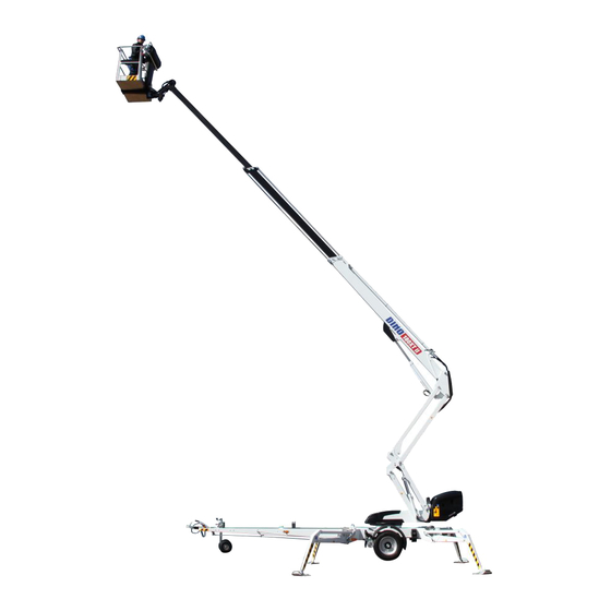
DINO 180T-1 TECHNICAL SPECIFICATION Max. working height 18,0 m (59’1”) Max. platform height 16,0 m (52’6”) Max. outreach 10,7 m (35’1”) Boom rotation continuous Platform rotation 90° Reach when turned refer to reach diagram Support width 3,88 m (12’9”) Transport width 1,78 m (5’10”) Transport length 7,35 m (24’1”) -
Page 8: General Safety Directives
DINO 180T-1 GENERAL SAFETY DIRECTIVES Make yourself familiar with the operators manual before using the lift! The operator's manual should be stored in the space reserved for it. Make sure that all persons working with the lift are familiar with the operator's manual.Inform new users about the operation of the lift and the manual. - Page 9 DINO 180T-1 No ladders, steps or other similar equipment may be used on the platform. Objects may under no circumstances be thrown out from the platform. The lift must not be used to move persons or objects between floors or different work levels. The safety devices must not in any circumstances be put out of function.
-
Page 10: Regular Inspection
DINO 180T-1 REGULAR INSPECTION A thorough inspection must be made at least once every twelve (12) months. The inspection should be made by a person who is technically trained and is familiar with the function, use and construction of the lift. Inspections should be recorded in a protocol that should always follow the unit and be stored in the space reserved for it. -
Page 11: Inspection On The Worksite
DINO 180T-1 INSPECTION ON THE WORKSITE 1. General Is the lift suited for the job at hand? Is the performance of the lift sufficient for the job (reach, loadability etc.)? Is the lift located safely on a site so that no negative influence on work safety is possible? Is there enough illumination for safe working? 2. -
Page 12: Safety Devices
DINO 180T-1 SAFETY DEVICES 1. Support outriggers A safety limit switch RK3 prevents use of the outriggers and the drive mechanism when the boom is lifted off the transport support. The limit switch is mounted on the tow bar boom support point. - Page 13 DINO 180T-1 2. Lifting the boom Lifting of the boom is prevented by safety limit switches when the wheels are not lifted off the ground, ie. when the lift is not supported by the supporting outriggers. The limit switches RK11, RK12, RK13 and RK14 are in the outriggers.
-
Page 14: Operating Controls
DINO 180T-1 OPERATING CONTROLS LOWER PANEL CONTROLS Operating switch 0 = Off 1 = Operation of support outriggers and moving the lift by hydraulic power (driving device) 2 = Controlling the boom from the platform 3 = Controlling the boom from the chassis Start -pushbutton Emergency stop - stop by pushing... -
Page 15: Controls Mounted On The Chassis
DINO 180T-1 CONTROLS MOUNTED ON THE CHASSIS Right rear support outrigger Left rear support outrigger Left front support outrigger Right front support outrigger Levelling gauge (chassis) Hydraulic movement, on - off Hydraulic movement, operating levers MOVEMENT OFF/ MOVEMENT ON FORWARD LEFT RIGHT WHEEL... -
Page 16: Platform Panel Controls
DINO 180T-1 PLATFORM PANEL CONTROLS Close the chassis control panel cover before using the platform controls (the cover must not be locked when using the lift). 17. Operating lever 18. Warning lights green = inside the reach limits = at the reach limit 20. -
Page 17: Measures To Be Taken If Stability Is Threatened
DINO 180T-1 MEASURES TO BE TAKEN IF STABILITY IS THREATENED The following factors can lead to loss of standing stability: a technical fault in the lift wind or other factors that can create sideways forces a decrease in ground firmness negligence when positioning and raising the lift A decrease in standing stability is mostly perceived as an increase in the inclination of the lift and boom. -
Page 18: Starting Up The Lift
DINO 180T-1 STARTING UP THE LIFT 1. Ground stability - Make sure that the ground is even and level, and hard enough to support the lift in a steady, level position (see table below). Ground material Density Max. ground pressure kg/cm²... - Page 19 DINO 180T-1 3. Power connection A. AC power - Connect the mains cable (230VAC or 110VAC) - Turn on the mains switch - Voltage should be • 230VAC (-10%/ +6%), frequency 50Hz, and mains fuse 16A • 110V ± 15V, frequency 50Hz, and mains fuse 16A (GB) •...
- Page 20 DINO 180T-1 7. Lower the front support outriggers (towbar) 8. Lower the rear support outriggers 9. Use the outriggers to adjust the chassis so that it stands level Make sure that the wheels are clearly off the ground - when the wheels are off the ground, the signal light 4A on the chassis control panel is lit. - make sure that all support outriggers are against the ground...
-
Page 21: Operating The Unit From The Chassis Control Panel
DINO 180T-1 OPERATING THE UNIT FROM THE CHASSIS CONTROL PANEL 10. Turn the operating switch (1) into position 3 - The boom can be operated using the levers 7, 8 and 9 - Test the emergency descent function as follows: 1. -
Page 22: Operating The Unit From The Work Platform
DINO 180T-1 OPERATING THE UNIT FROM THE WORK PLATFORM 11. Turn the operating switch (1) into position 2 and take away the key. The cover of the chassis control panel must not be locked with key. - now you can operate the lift from the work platform lever First push the rocking switch on the control lever end, and carefully move the lever in the desired direction of movement. - Page 23 DINO 180T-1 12A. Measures to be taken after overload situation. (Overload limit switch RK5 disconnects the electric circuit from the controls and the platform alarm horn on.) - retract the telescope by pressing ”telescope in” -pushbutton (30 or 31) until the platform reaches the permissible reach zone (the green light in the upper control panel is lit) - after this the lift can be used normally Telescope in –pushbutton (30 tai 31) always works when the electric motor is running or when...
- Page 24 DINO 180T-1 17. Important when raising the platform. The possible platform movements (reach) depend on the platform load (refer to technical data). The movements are controlled by two safety limit switches, RK4 and RK5 mounted beneath a cover. The switches must not be adjusted or tampered with in any way. Inspections and adjustments may be made only by an authorized service mechanic.
- Page 25 DINO 180T-1 19. When moving the platform, remember the following - special care should be taken in the vicinity of high voltage cables - do not exceed the max. allowed sideways load (400N) (88 lbs) - make sure that no part of the platform or the operator can come into contact with open-wire cables - objects may under no circumstances be thrown out of the platform...
-
Page 26: Emergency Descent System
DINO 180T-1 EMERGENCY DESCENT SYSTEM As a precaution for a possible power failure, the lift is equipped with a battery operated emergency descent system. 1. Emergency descent system - Battery, 12V 26Ah - Charger - 12 VDC hydraulic unit 2. Servicing the battery - The system is equipped with an automatical, thermal and short circuit protected charging system rated power... -
Page 27: Driving Device
DINO 180T-1 DRIVING DEVICE The hydraulic driving device should be used for those short moves on the working site, for which the towing vehicle cannot be used. 1. Do not drive downhill with the driving device at the front if the inclination of the surface is more than 5 per cent, i.e., more than 1/20 (corresponding to a descent of 0.5 m over a distance of 10 m). - Page 28 DINO 180T-1 Driving - Adjust the running speed to ¾ of the maximum (gasoline/ petrol) The speed of the driving device depends on the aggregate running speed. - switch the power train into position ”driving” MOVEMENT OFF/ MOVEMENT ON - Turn the operating switch (1) into position "support outriggers" - Make sure that the platform is in transport position and that the support outriggers are completely raised - Make sure that the mains cable is long enough for moving the lift (by using AC power)
- Page 29 DINO 180T-1 - when driving, use the control levers to steer FORWARD LEFT RIGHT WHEEL WHEEL REARWARD - Do not drive the jockey wheel onto obstacles or into potholes NOTE! If one wheel encounters an obstackle, the lift might turn abruptly! - When finishing driving, pull the parking brake - switch off the power train MOVEMENT OFF / MOVEMENT ON...
-
Page 30: Special Instructions For Winter Use
DINO 180T-1 SPECIAL INSTRUCTIONS FOR WINTER USE - The lift must not be used in temperatures below -20°C (-4°F) - When the lift is used in cold conditions the power unit should be run for a couple of minutes before attempting hydraulically actuated movements - Start by making short warm-up movements to force warmed-up oil into the cylinders, which improves the functioning of the valves. -
Page 31: Ending The Days Work
DINO 180T-1 ENDING THE DAYS WORK 1. Retract the telescoping boom fully. 2. Check that the platform is perpendicular to the boom. 3. Lower the boom and platform onto the towbar - The limit switch mounted on the transport support prevents operating the support outriggers if the platform is not lowered completely 4. -
Page 32: Preparing The Lift For Transport
DINO 180T-1 PREPARING THE LIFT FOR TRANSPORT 1. Retract the telescoping boom fully. 2. Check that the platform is perpendicular to the boom. 3. Lower the boom and platform onto the towbar - The limit switch mounted on the transport support prevents operating the support outriggers if the platform is not lowered completely 4. -
Page 33: Connecting To The Towing Vehicle
DINO 180T-1 CONNECTING TO THE TOWING VEHICLE 1. Lift the handle of the ball coupling at the same time as you push it forwards. This opens the ball coupling. 2. Place the ball coupling onto the towing ball and push lightly downwards. The coupling automatically locks into place. -
Page 34: Service And Maintenance
DINO 180T-1 SERVICE AND MAINTENANCE GENERAL - Inspections and service should always be performed as described in this manual. - More complicated repairs and service measures should be performed by specially trained personnel (the manufacturer, or manufacturers representative). - No changes or additions may be made to the lift without written consent from the manufacturer. - Faults and wear that might influence the operational safety of the unit must be repaired and corrected immediately. -
Page 35: Inspections And Service
DINO 180T-1 INSPECTIONS AND SERVICE 1. The first service inspection should be made after 20 hours of use: - Change the pressure filter cartridge. - Adjust the braking system, refer to page 40. - Check the tightness of the wheel bolts after about 100 km (about 60 miles) driving (90 Nm) 2. -
Page 36: Lubrication Plan
DINO 180T-1 LUBRICATION PLAN... - Page 37 DINO 180T-1 Every 50 hours 1. Overload protection (articulated shaft) bearings 2. Outrigger cylinder joint bearing surfaces 3. Outrigger joint bearing surfaces 4. Outrigger footplate joint bearing surfaces 5. Boom bearing surfaces 6. Platform bearing surfaces 7. Stabilization cylinder bearing (except for the joint bearing on the upper stabilization cylinder piston rod side) 8.
- Page 38 DINO 180T-1...
-
Page 39: Hold- And Load Regulating Valves
DINO 180T-1 HOLD- AND LOAD REGULATING VALVES Functional check 1. Checking the outrigger cylinder holding valves with respect to leaks is made by lifting the unit up with the outriggers and measuring, separately at each outrigger, chassis height from the ground. After a few minutes, measure the height again. -
Page 40: Wheel Brakes And Bearings
DINO 180T-1 WHEEL BRAKES AND BEARINGS Adjusting the brakes Jack up the lift so that the wheels will rise off the ground and support it in this position. Make sure that the wheels can rotate freely. The brake rods must be slack (with the handbrake released). - Page 41 DINO 180T-1 Apply the handbrake and push the lift backwards until both its wheels lock; when doing so the handbrake lever should rise up and move 5-10 mm backwards from the limiter. Release the handbrake. 5 –10 mm Adjust the length of the return springs to 90 mm.
- Page 42 DINO 180T-1 Adjusting the bearings The wheel bearings are lubricated for life and do not need any service. (they do not need additional lubrication and they cannot be adjusted). Service intervals 500 km (300 miles) Running in 5000 km (3000 miles) Brake adjustment, lubricate the moving parts in the overrun device.
-
Page 43: Platform Stabilization System
DINO 180T-1 PLATFORM STABILIZATION SYSTEM - The stabilization is effected with a slave cylinder: mounted under the platform and controlled by the master cylinder the levelling of the platform depends on the tightness of the stabilization system valves the system consists of the following parts: 1. -
Page 44: Regular Servicing
DINO 180T-1 REGULAR SERVICING The lift should be serviced regularly at 11 - 12 month intervals. If it is used in corrosive and demanding ambient conditions (Moist, corrosive chemicals etc.), the technical devices and structure are subjected to harder stresses. In these conditions it is recommended that the servicing and checks be made at shorter intervals. - Page 45 DINO 180T-1 2. Change the hydraulic oil and filter cartridge. (protect your skin against hydraulic oil) - Drain the oil tank through the draining plug, with all cylinders in retracted position - Clean the tank with a suitable solvent and then rinse it. - Renew the pressure side filter - Reassemble the draining plug - Refill tank with fresh oil.
- Page 46 DINO 180T-1 4. Inspect the support outrigger joints. - Lower the outriggers slightly. - Turn the outriggers back and forth horizontally and check for play in the joints. - Inspect function and condition of the outrigger limit switch mechanism - If necessary, renew the joints and pins. - Lubricate the joints (refer to lubrication plan).
- Page 47 DINO 180T-1 6. Inspect the boom and the chassis - Inspect the platform, its attachment and the boom, with the telescope extended. - Check boom joints and gliding surfaces and adjust if necessary. Lubricate the gliding surfaces. - Check the condition of the Flyer- chain, fixations and adjustment - Check the fixation of the unloaded Flyer-chain to the boom by pulling...
- Page 48 DINO 180T-1 7. Inspect the towbar/overrun device - Fastening, bolt and nut condition and tightness - Play - Ball coupling condition - Locking mechanism condition - Check that the overrun brake mechanism moves freely: stop the lift, as described on page 31 push in the ball coupling and towbar the ball coupling/towbar should automatically return to the original extended position, powered by the gas-filled hydraulic shock absorber...
- Page 49 DINO 180T-1 10. Inspect safety device functions, operating from chassis control panel. - Lift the platform slightly off transport position. - the outriggers must not function in any position of the operating switch - Lift the arm and check the following 1.
-
Page 50: Testing The Load Limits
DINO 180T-1 TESTING THE LOAD LIMITS - Load the platform with exactly 80 kg (177 lbs) 100 mm (4 ") from the trail edge of the platform bottom - Operating from the lower control panel, move boom to horizontal position. - Extend the telescope as far as possible. - Page 51 DINO 180T-1 Notes...
-
Page 52: Setting The Overload Devices Rk4 And Rk5
DINO 180T-1 SETTING THE OVERLOAD DEVICES RK4 AND RK5 When servicing, always test both overload limit switches - Load the platform with for example 80 kg (177 lbs) - Move the boom into horizontal position... - Page 53 DINO 180T-1 Setting procedure, alternative 1. - Set the actuating point of RK4 far enough to ensure that RK5 is actuated before RK4 - Extend the boom, and measure one part of it (stroke) - The stroke should be 3000 ± 50 mm (118 ± 2 in) - Tighten the adjustment locking nut and test the actual values once more - RK4 should be set to actuate before RK5 - Extend the boom and measure the stroke...
- Page 54 DINO 180T-1 11. Pressure measurements - Connect the pressure gauge to the measuring point - Connect the pressure gauge to the measuring point - Max. pressure, oil at working temperature 40 - 60 °C (105 - 140 ˚F) 21 - 21,5 MPa (210 - 215 bar) (3050 - 3100 psi) - When turning, max.
- Page 55 DINO 180T-1 13. Warning signs - Make sure that all warning signs are in good condition and can be easily read. Replace damaged signs. 14. Inspect the brakes and driving device - Remove the wheels - Clean the brake system and check the adjustment, the brake shoes should be able to move freely and the return springs should be in order - Renew the brake linings if necessary - Adjust the brakes...
-
Page 56: Inspecting The Lift
DINO 180T-1 INSPECTING THE LIFT Lifting and hoisting equipment used at construction sites should always be inspected before use. The lift should be inspected periodically, at least once a week during the work period. If defects are discovered, they should be noted in a logbook and reported to the foreman. FIRST INSPECTION The Dino lifts are subjected to a first inspection and load test at the manufacturer. -
Page 57: Daily Inspections
DINO 180T-1 DAILY INSPECTIONS At the beginning of every work shift, or after the lift has been moved to another work site, the user maust always make the following inspections: - Ascertain the carrying capacity of the ground where the lift is to be used (refer to table on page 18) - Check the standing stability and outriggers - Check that the unit stands level - Check the functioning of the emergency stop -button in both platform and chassis operating panels... -
Page 58: Inspections Once A Month
DINO 180T-1 INSPECTIONS ONCE A MONTH (MAINTENANCE INSPECTION) These inspections must be performed by a trained mechanic familiar with the lift. Inspection list: - All the above mentioned daily inspections - Boom and platform attachment - Platform stabilization unit, condition and function - Optical inspection of the following supporting structures: - Frame - Turning device... -
Page 59: Regular Inspection (Annual)
DINO 180T-1 REGULAR INSPECTION (ANNUAL) This inspection must be made by a technically trained mechanic who is familiar with the specifications and use of the equipment. Steel structures, safety devices and operating controls should be inspected with special care. Clean the unit thoroughly. Inspection list: - All the above mentioned monthly inspections - All the above mentioned monthly inspections... - Page 60 DINO 180T-1 - Manually operated directional valves - Check that the support outrigger and driving device valves work correctly and that there are no movements when the spindle is in mid-position - Slipring-hydraulical swivel - Check that there are no oil leaks - Check that the turning lever is well attached and does not stick - Cylinders - Move the outriggers into support position and inspect the condition of the...
- Page 61 DINO 180T-1 - Inspect the boom pivot joints - Check that the boom joint spindle, bearings and spindle fixations are in good condition - Inspect the support outriggers and support plates - Inspect the mechanical structure and welds. The outriggers must not be deformed or damaged.
-
Page 62: Extraordinary Inspection
DINO 180T-1 - Inspecting the chassis - General condition - Inspect the tow-bar/frame fastening - Check the condition and fastening of the overrun device - Inspect the axle and its fixation - Inspect brake wires and rods. - Inspect the wheel rims, bolts, tires and tire pressures - Check the driving device, with respect to the fastening of the separate parts and condition of the covers of the electrical parts - Check the condition of the boom transport support... -
Page 63: Test Loading In Conjunction With The Regular Service
DINO 180T-1 TEST LOADING IN CONJUNCTION WITH THE REGULAR SERVICE 1. Place the lift on an even surface with good carrying capacity, and lift it up with the supporting outriggers. Lift it as high as possible with the support outriggers (the support area is as small as possible) 2. -
Page 64: Fault Finding
DINO 180T-1 FAULT FINDING CAUSE REMEDY 11. The electric motor does not start when the operating switch is in position 1, 2 or 3 and the start button is pressed. - Emergency push button jammed on - Lift up the emergency push button and press the start button - Fuse F1 broken - Renew the fuse (10A) - Page 65 DINO 180T-1 CAUSE REMEDY 4. Platform movement problems. Only one movement can be executed. - Irregular and undefined malfunctions - Check that the hydraulic fluid and filter have been replaced on time - thoroughly clean the solenoid valve spindles and housings. Observe utmost cleanliness, malfunctions can be caused by invisible polluting particles - The malfunction can also be caused by contact...
- Page 66 DINO 180T-1 CAUSE REMEDY 8. The boom cannot be raised - refer to item 4 - the solenioid valve is open - other causes, ref. solenoid valve sticking - Turning function activated when using raise - turning solenoid valve stuck in position control "turning"...
- Page 67 DINO 180T-1 CAUSE REMEDY 12. Platform moves forwards - boom load regulating (2-way) valve leaks - as above 13. The support outriggers do not work, although the switch is in position 1 - boom does not rest on the support - move boom onto support - Boom/support outrigger solenoid valve - ref.
- Page 68 DINO 180T-1 CAUSE REMEDY 17. Braking power too weak - braking system adjustment too loose, (also - adjust the braking system (ref.to page 40) check linkage) - brake linings not run-in - apply the handbrake very lightly and drive slowly about 1-2 miles - brake linings "glazed", dirty or polluted by oil - replace the brake shoes (complete set) - clean the friction surfaces on the brake drum...
- Page 69 DINO 180T-1 CAUSE REMEDY 23. Ball coupling does not lock itself onto the ball - ball bearing cup dirty - clean and lubricate - ball on towing vehicle too big - measure the ball. According to DIN74058 the ball diameter should be between 50 mm and 49,5 mm.
-
Page 70: Hydraulic System, General Information
DINO 180T-1 HYDRAULIC SYSTEM, GENERAL INFORMATION To be able to carry out any movement two solenoid valves must always be actuated. Thus: - actuator valve and boom OUTRIGGERS/ BOOM (PROPO) - actuator valve and telescope - actuator valve and platform BOOM - actuator valve and turning TELESCOPE... - Page 71 DINO 180T-1 Notes...
-
Page 72: Electric Components' Function
DINO 180T-1 ELECTRIC COMPONENTS' FUNCTION LOWER CONTROL PANEL (PK), RELAYS R2: AUXILIARY RELAY FOR INTERRUPTING BOOM-DOWN FUNCTION. THE SAFETY LIMIT SWITCH RK4 CONTROLS THE RELAY RL2. RELAY DELAY IS INDUCED BY THE PROCESSOR CARD POTENTIOMETER TR2 (PICTURE ENCLOSED). TIME IS READY-SET AT ABOUT 0,6 SEC. -
Page 73: Lower Control Panel (Pk), Switches
DINO 180T-1 R22: WHEN RK4 HAS ACTUATED (RED LIGHT ON) THE RL22 AUXILIARY RELAY PREVENTS THE BOOM FROM DESCENDING WHEN JUMPING ABOUT ON THE PLATFORM. DELAY TIME, (APPR. 2,5 S.) FOR THE PROSESSOR BOARD POTENTIOMETER TR3 READY-SET (PICTURE ENCLOSED). R24: AUXILIARY RELAY, HYDRAULIC UNIT OFF. SR2: SAFETY RELAY FOR MONITORING SUPPORT OUTRIGGERS. -
Page 74: Upper Control Panel (Ok), Relays
DINO 180T-1 UPPER CONTROL PANEL (OK), RELAYS R13: CONTROL RELAY FOR GREEN (H1) AND RED (H2) LED SIGNAL LIGHTS. RELAY RL13 IS CONTROLLED BY SAFETY LIMIT SWITCH RK4 R14 AND R15: FUNCTION RELAYS CONTROLLED BY THE INDUCTIVE LIMIT SWITCHES RK9 AND RK10 FOR CONTROLLING THE PLATFORM TURNING (RIGHT-LEFT) ELECTRIC CYLINDER (RIGHT BUTTON ON JOYSTICK) R16 AND R17: RELAYS PREVENTING OVERLAPPING FUNCTIONS, ACCENTUATE AND BACK UP THE JOYSTICK GATE PATTERN FUNCTION... -
Page 75: Limit Switches
DINO 180T-1 LIMIT SWITCHES RK3: : PREVENTS THE OUTRIGGER FUNCTIONS WHEN THE BOOM IS NOT SET DOWN ONTO THE SUPPORT (IN TRANSPORT POSITION) AS WELL AS DRIVING DEVICE FUNCTIONING (CONTROLS RELAY RL30) RK4: SAFETY LIMIT SWITCH FOR THE REACH AREA. RK5: BACKUP LIMIT SWITCH FOR RK4 SAFETY LIMIT SWITCH. -
Page 76: Other Markings
DINO 180T-1 OTHER MARKINGS F4: PROPO -CONTROL BOARD FUSE 1,6A H3: YELLOW LED SIGNAL LIGHT. SHOWS THAT OUTRIGGER LIMIT SWITCHES RK11, RK12, RK13 AND RK14 HAS ACTIVATED SPV1: MAIN POWER SWITCH CONNECTS - BREAKS BATTERY (-) CONNECTION. Q1: CONTROL FUNCTION SELECTOR SWITCH. I = SUPPORT OUTRIGGERS, II = PLATFORM CONTROL PANEL, III = CHASSIS CONTROL PANEL ÄM1: SIGNAL HORN... -
Page 77: Propo -Control Card
DINO 180T-1 PROPO -CONTROL CARD (48.2127) 1. MAXIMUM MOVEMENT SPEED 2. MINIMUM START-UP 3. FUNCTIONAL DELAY (0) 4. FREQUENCY Propo-control card is adjusted before regulating potentiometers TR1, TR2 and TR3 (Exist on the mainboard 48.2197). (Propo -control card has been adjusted at the factory.) Instructions for the setting of the propo card IN FOLLOWING ORDER: 2. -
Page 78: Electronic Components
DINO 180T-1 ELECTRONIC COMPONENTS 4505 → REFERENCE PART NR DESCRIPTION 48.2194 BATTERY DL8.058 THERMAL RELAIS 48.647 10A FUSE 48.640 10A FUSE F4, F5 48.3030 1,6A FUSE 48.3036 + 48.1034 AUTOMATIC FUSE 48.2204 GREEN LED -SIGNAL LAMP 48.2203 RED LED -SIGNAL LAMP 48.2152 YELLOW LED -SIGNAL LAMP 48.0111... -
Page 79: Electric Schema
DINO 180T-1 ELECTRIC SCHEMA 4433 →... - Page 80 DINO 180T-1...
- Page 81 DINO 180T-1...
- Page 82 DINO 180T-1...
- Page 83 DINO 180T-1...
- Page 84 DINO 180T-1...
- Page 85 DINO 180T-1...
- Page 86 DINO 180T-1...
- Page 87 DINO 180T-1...
- Page 88 DINO 180T-1...
- Page 89 DINO 180T-1 Notes...
-
Page 90: Hydraulic Components
DINO 180T-1 HYDRAULIC COMPONENTS 4445 → REF. NR. PART NR. DESCRIPTION 47.171 PRESSURE FILTER 47.2271 HYDRAULIC PUMP 47.2273 HYDRAULIC MOTOR 47.2319 HYDRAULIC MOTOR 47.2576 FLOW RESISTANCE VALVE 47.2659 FLOW RESISTANCE VALVE 47.2660 SWITCHING LOAD VALVE 47.2720 TWO-WAY DIRECTIONAL VALVE 47.2721 TWO-WAY DIRECTIONAL VALVE 47.2722 LOAD REGULATING VALVE... -
Page 91: Hydraulic Scheme
DINO 180T-1 HYDRAULIC SCHEME 4371, 4375, 4387 →... - Page 92 DINO 180T-1 Notes...
Need help?
Do you have a question about the DINO 180 T and is the answer not in the manual?
Questions and answers