ABB REF 542plus Technical Reference Manual
Protection relay
Hide thumbs
Also See for REF 542plus:
- Operator's manual (134 pages) ,
- Installation manual (52 pages) ,
- Product manual (28 pages)
Table of Contents
Advertisement
Advertisement
Table of Contents

Related Manuals for ABB REF 542plus


Summary of Contents for ABB REF 542plus
- Page 1 REF 542plus REF 542plus Technical Reference Manual...
-
Page 3: Table Of Contents
Binary inputs and outputs......26 4.9. Interfacing a station automation system ....... 27 4.10. Embedded Web Server........... 28 4.11. CAN Open (only for ABB switchgear companies) ..29 4.12. ABB Product Data Registration ........30 5. Construction............31 5.1. Base unit versions ........... 31 5.2. - Page 4 Multifunction Protection and Switchbay Control REF 542plus REF 542plus 1MRS755859 Unit Technical Reference Manual 6.3. Configuration restriction ..........44 6.4. Binary inputs and outputs.......... 45 6.4.1. BIO module with mechanical output relays (version3) ........... 45 6.4.2. BIO module with static outputs....... 46 6.5.
-
Page 5: Copyrights
This document and parts thereof must not be reproduced or copied without written permission from ABB Oy, and the contents thereof must not be imparted to a third party nor used for any unauthorized purpose. -
Page 7: Introduction
Technical Reference Manual Introduction 1.1. This manual This manual provides thorough information on the protection relay REF 542plus and its applications, focusing on giving a technical description of the relay. 1.2. Use of symbols This publication includes the following icons that point out safety-related conditions... -
Page 8: Product Documentation
Updated to software version V4E03x. 30.04.2007 Updated to software version V4E04x. 15.08.2007 Document updated 28.09.2007 Document updated 14.02.2008 Document updated 23.10.2008 Updated to software version V4F06x Applicability This manual is applicable to the REF 542plus release 2.6, software version V4F06x. -
Page 9: Safety Information
1MRS755859 Multifunction Protection and Switchbay Control REF 542plus REF 542plus Unit Technical Reference Manual Safety information Dangerous voltages can occur on the connectors, even though the auxiliary voltage has been disconnected. Non-observance can result in death, personal injury or substantial property damage. -
Page 11: General
The exceptional flexibility and scalability of this new generation device lead to a smart solution where the traditional approach would be ineffective and expensive. The following figures Fig. 3.-1 and Fig. 3.-2 show examples of the REF 542plus installation in several switchgears. A050395 Fig. - Page 12 Fig. 3.-2 REF 542plus installed in an air-insulated switchgear (AIS) REF 542plus is composed of two parts: a base unit and a separate human machine interface (HMI). The base unit contains the power supply, the processor board, the analog input board and binary input and output (I/O) modules, as well as optional modules for supplementary functions.
- Page 13 Mounting of the central unit in the LV compartment and the HMI on the door REF 542plus is a real-time system. A digital signal processor (DSP) carries out the measurement and protection functions, and a micro controller (MC) the control functions.
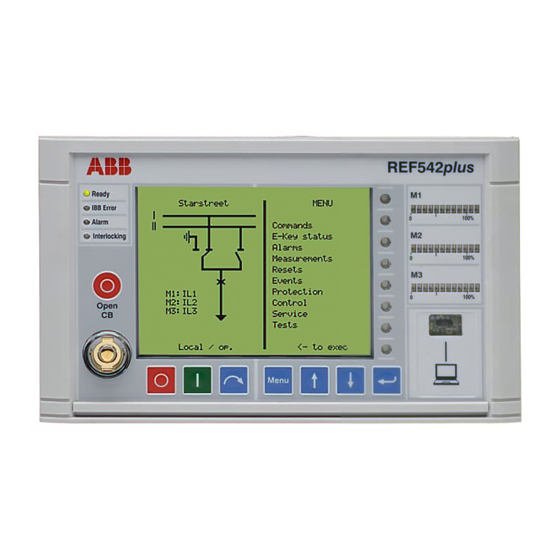
- Page 14 Binary Input Output Board(s) A050397 Fig. 3.-4 REF 542plus block diagram The HMI control unit, as shown in Fig. 3.-5, features a back-illuminated liquid crystal display (LCD), eight push buttons, several LEDs and an electronic key interface. The language of the display can be selected by using the related configuration software tool, which is also used to define the protection and the control scheme.
- Page 15 Network Communication LED This LED is meaningful only when the REF 542plus is equipped with a communication module and configured to use it. When a communication module is detected inside the unit, the LED turns on to green.
- Page 16 LEDs. The assignment of the LED to a specific condition is done with the Operating Tool. PC interface PC interface is the infrared serial (IrDa) interface port to connect the REF 542plus with a personal computer. By using the appropriate cable and the Operating Tool, the following actions are possible:...
- Page 17 Typical examples might be: start of a transfer switch or of any other automation sequence, fault recorder activation, start of a load shedding sequence and so on. Due to the user defined command buttons, REF 542plus automation capabilities can cope with any requirements.
-
Page 19: Functions
The REF 542plus unit provides a wide range of logical functions so that each specific requirement can be met. The functions include logical gates such as AND, OR, timers, counters, pulse generators, flip-flops and so on. -
Page 20: Directly Measured Values
Group 3 can get any type of signals, for example, 2 currents, 2 voltages, or 1 current and 1 voltage. REF 542plus analog input is designed to be very flexible in order to support all the protection functions of the unit itself. -
Page 21: Monitoring And Self-Diagnosis
Technical Reference Manual 4.2.4. Monitoring and self-diagnosis The REF 542plus offers several features for monitoring the primary part as well for self-diagnosis. The following computed quantities are available for primary part monitoring: Maximum and mean currents in the observation period (0 ... 30 min) -
Page 22: Control
4.4. Control The control and automation capabilities inside the REF 542plus are extremely powerful. Simple interlocking against switching errors as well complex load- shedding schemes can be easily implemented with the control possibilities offered by the REF 542plus. -
Page 23: Event Recording
1.4, which allows horizontal communication among the REF 542plus units connected on the interbay bus Using the CAN Open digital fieldbus (only to be applied by the ABB switchgear companies) The REF 542plus foresees different control modes, selectable with the control key. -
Page 24: Time Synchronization
4.7. Time synchronization REF 542plus is equipped with an internal real-time clock, which is used to time stamp events. The internal clock is buffered by a special capacitor. In case of a DC power supply failure, the stored electrical energy in the capacitor ensures continued operation of the internal clock for at least another two hours. -
Page 25: Interface To The Primary Process
Technical Reference Manual standard protocol IEC 60870-5-103, IEC 61850 or modified Modbus RTU protocol are available. If better accuracy is required, REF 542plus can be synchronized using the dedicated IRIG-B optical input port and a GPS master clock. The accepted timeformats are IRIG format B 000, B002 and B003. -
Page 26: Binary Inputs And Outputs
The numerical integration of the signal is performed by the DSP in the REF 542plus unit. The current sensors cover a range between 0.5 to 2.0 of the rated current. The 80 A current sensors, for example, are very suitable for applications between a current range of 40 A to 160 A. -
Page 27: Interfacing A Station Automation System
An optional communication module can be provided for interfacing a station automation system. The six different protocols available for the REF 542plus make possible to interface any kind of station automation system, both from ABB or from third parties. The following typical functions are possible:... -
Page 28: Embedded Web Server
Clicking on the address button, the specific REF 542plus unit single line diagram is loaded, with also all the information that would be normally available standing in front of the HMI. REF 542plus data are available in read mode only (monitoring access). -
Page 29: Can Open (Only For Abb Switchgear Companies)
4.11. CAN Open (only for ABB switchgear companies) The REF 542plus is equipped on the main module with a CAN Open standard interface. The CAN Open interface has two main purposes: Replacing the switchgear internal hard-wired connections by means of a high- speed digital bus;... -
Page 30: Abb Product Data Registration
CAN Open standard, thus making the automation capabilities of the REF 542plus almost unlimited. The Fig. 4.11.-1 describes an architecture where two REF 542plus units and some IO modules are connected with the CAN Open. -
Page 31: Construction
Construction 5.1. Base unit versions The REF 542plus base unit housing is made from aluminum sheets. Its exterior is chromatized both to protect the housing against corrosion and to improve immunity against EMC disturbances. Two different housings are available: Standard... - Page 32 Multifunction Protection and Switchbay Control REF 542plus REF 542plus 1MRS755859 Unit Technical Reference Manual ± 0,1 233,5 ± 0,1 ca. 70 261,5 ± 0,1 233,5 A051268 Fig. 5.1.-1 Standard housing version dimensions. Wide housing summary One power supply One mainboard module...
- Page 33 1MRS755859 Multifunction Protection and Switchbay Control REF 542plus REF 542plus Unit Technical Reference Manual Optionally the communication module Optionally the 4 ... 20 mA analog input module or the 4/0 ... 20 mA analog output module ± 0,1 233,5 ± 0,1 261,5 ca.
-
Page 34: Mounting And Installation
Multifunction Protection and Switchbay Control REF 542plus REF 542plus 1MRS755859 Unit Technical Reference Manual 5.2. Mounting and installation The Fig. 5.2.-1 shows an example of wide housing base unit installation inside a low voltage compartment. A051270 Fig. 5.2.-1 Base unit installation in the low voltage compartment of GIS switchgear Use always the broad flexible cables for grounding of the housing. - Page 35 1MRS755859 Multifunction Protection and Switchbay Control REF 542plus REF 542plus Unit Technical Reference Manual A051271 Fig. 5.3.-1 Dimensions of the HMI version without cover The advisable panel hole is 240,5 mm x 140,5 mm. The existing connectors for the former version of the HMI can be used.
- Page 36 Multifunction Protection and Switchbay Control REF 542plus REF 542plus 1MRS755859 Unit Technical Reference Manual A070119 Fig. 5.3.-2 Dimensions of the HMI version with cover The advisable panel hole is the same as before.
-
Page 37: Technical Data
REF 542plus REF 542plus Unit Technical Reference Manual Technical data 6.1. Analog inputs 6.1.1. Measurements The REF 542plus unit uses the same analog inputs both for measurements and protections. Table 6.1.1.-1 Measurements Quantity Class Range Phase current, earth current 0.1-4I Line voltage, phase voltage 0.2-1.5V... -
Page 38: Analog Input Modules
Multifunction Protection and Switchbay Control REF 542plus REF 542plus 1MRS755859 Unit Technical Reference Manual Table 6.1.2.-5 Current and voltage sensor input values Voltage at rated current I 150 mV (rms) Voltage at rated voltage U 2 V (rms) Rated frequency f 50 Hz or 60 Hz 6.1.3. -
Page 39: Protection Functions Technical Data
Unit Technical Reference Manual The REF 542plus is a protection and control unit and the programmed automation logic is executed cyclically in a PLC–style mode. The cycle time, in the range of ten millisecond, is depending upon the logic complexity. - Page 40 Multifunction Protection and Switchbay Control REF 542plus REF 542plus 1MRS755859 Unit Technical Reference Manual Is = 0.050 – 40.000 x In 50/51 Overcurrent with t (def) = 0.015 – 300.000 s free A = 0.005 – 200.000 programmable P = 0.005 – 3.000 characteristic (8 B = 0.000 –...
- Page 41 1MRS755859 Multifunction Protection and Switchbay Control REF 542plus REF 542plus Unit Technical Reference Manual 67N Sector Earth fault Direction = Enable (directional behavior)…Disable (non directional Sector directional behavior) (10 thresholds Start Criteria = neutral current magnitude/ neutral current available) basic angle Io>...
- Page 42 Multifunction Protection and Switchbay Control REF 542plus REF 542plus 1MRS755859 Unit Technical Reference Manual 51LR Locked rotor IMn = 0.200 ... 2.000 In (motor current) (definite time Is = 1.000 ... 20.000 IMn (start value) characteristic) t = 40 ... 30 000 ms Number of starts n (warm) = 1 ...10 (number of warm starts)
- Page 43 1MRS755859 Multifunction Protection and Switchbay Control REF 542plus REF 542plus Unit Technical Reference Manual Distance Net type = high/low ohmic protection earth start IE> used, unused switching onto faults = normal, overreach zone, trip after start Signal comparison overreach scheme time set = 30 ...
-
Page 44: Configuration Restriction
Op. time = 1.0 ... 1000.0 s 6.3. Configuration restriction There are some limitations that must be respected during the REF 542plus configuration. At most 24 protection functions can be configured inside the unit. A protection function can activate only one single direct channel. -
Page 45: Binary Inputs And Outputs
(power transistor types). For both of them, binary inputs are of the same type, insulated with optic couplers. Inside a REF 542plus unit, only modules of the same type have to be present. It is not possible to have both static and electromechanical modules. -
Page 46: Bio Module With Static Outputs
Multifunction Protection and Switchbay Control REF 542plus REF 542plus 1MRS755859 Unit Technical Reference Manual Hardware fixed filter time 1 ms. Additional filter time can be configured in software. 6 power outputs (channels Maximum operating voltage 250 V AC/DC BO 1 to 6) -
Page 47: Interfaces
SPA, optical plastic fiber interface with snap-in type connector; or glass fiber (multi mode) with F-SMA or ST connectors LON (according to ABB LAG1.4), glass fiber (multi mode) optical interface with ST connectors IEC 60870-5-103 with extension according to VDN guidelines for controlling,... -
Page 48: Power Supply
Technical Reference Manual Ethernet Interface Standard RJ45 connector on the main module CAN Open (optional and only for ABB switchgear companies). Open style connector compliant with CAN Open standard and ISO11898 Input for time synchronization (optional, the supported protocol is IRIG, format B000, B002, B003). -
Page 49: Environmental Conditions
Front: IP 54 Rear: IP 20 6.9. Tests Type test Detailed information on type tests are listed in the document: REF 542plus. Type test certificate, 1MRS756443. Protection functions Protection functions are type tested according to IEC 60255 standard series. Electromagnetic compatibility... - Page 50 Dry heat test according to IEC 60068-2-2. Certifications ATEX The REF 542plus unit, when used as a motor protection, can optionally comply with the directive 94/9/EC from the European Community for explosives environments. This directive defines how motor protection units behave in potentially explosive environment.
-
Page 51: Ordering
V4D02 and release 2.5 with version V4E04. For releases 1.1 and 2.0 the REF 542plus unit is delivered with the previous HMI V4 and for release 2.5 with the new HMI V5. Order the DNV certifies for marine application. Note that the DNV version can only deliver with the previous HMI V4. - Page 52 Application areas NUMBER CODE NAME DESCRIPTION REF 542plus Normal operation REF 542plus DNV Marine and offshore application REF 542plus ATEX-1 Protection of motor in an explosive area (Release 1.1) REF 542plus ATEX-2 Protection of motor in an explosive area (Release 2.0) REF542plus ATEX-2.5...
- Page 53 1MRS755859 Multifunction Protection and Switchbay Control REF 542plus REF 542plus Unit Technical Reference Manual Table 7.-5 Analog I/O modules NUMBER CODE NAME DESCRIPTION none No analog input or output Empty analog I/O module slot 750211/801 Analog input module 4- Analog input module for 4-20 mA...
- Page 54 Multifunction Protection and Switchbay Control REF 542plus REF 542plus 1MRS755859 Unit Technical Reference Manual NUMBER CODE NAME DESCRIPTION 750132/806 Binary I/O3 - 88-132 V/ As no. D + one static output channel 72 V DC, with static for energy metering...
- Page 55 1MRS755859 Multifunction Protection and Switchbay Control REF 542plus REF 542plus Unit Technical Reference Manual NUMBER CODE DESCRIPTION 750170/854 3 sensors + 3 CT + 1 CT/0.2 A + 1 VT 750170/855 3 sensors + 3 CT + 1 CT/0.2 A + 1 CT/0.2 A Table 7.-9...
- Page 56 Multifunction Protection and Switchbay Control REF 542plus REF 542plus 1MRS755859 Unit Technical Reference Manual Table 7.-11 Enclosure versions NUMBER CODE NAME DESCRIPTION 750154/801 Normal base unit Normal version 750102/801 Wide base unit Wide version 7 6 B 6 A 3 3 3 03 6 S Table 7.-12...
- Page 57 A limitation of the protection functionality with a software license. Contact your local ABB organization for more detailed information. The software level Base can only be ordered by ABB switchgear companies. It is of the same level as the software level Distance.
- Page 58 B = Basic S = Standard version (For more information, see Table 7.-3) Applications 6 = REF 542plus A = REF 542plus DNV/marine B = REF 542plus ATEX-1 (For more information, see Table 7.-2) Feeder terminal family code 7 = REF 542plus (For more information, see Table 7.-1)
-
Page 59: Connections
8.1. Connector plates The pictures show the connections for REF 542plus both in the standard and wide housing versions. The wide housing version can house three binary input and output modules, the communication module, the 0/4 ... 20 mA analog output module or alternatively the 4 ... - Page 60 7 11 15 19 10 14 10 14 X76 X75 A051273 Fig. 8.1.-2 REF 542plus standard housing connections with mixed analog input connector and connector for the 0/4 ... 20 mA analog output module 10 14 X76 X75 A051274 Fig. 8.1.-3 REF 542plus wide housing connections plate The connectors meaning is explained in the following Table 8.1.-1.
- Page 61 1MRS755859 Multifunction Protection and Switchbay Control REF 542plus REF 542plus Unit Technical Reference Manual Table 8.1.-1 Meaning of connectors Connector Meaning Base unit power supply First BIO, inputs First BIO, outputs Second BIO, inputs Second BIO, outputs Third BIO, inputs Third BIO, outputs Analog output 0/4 ...
- Page 62 Unit Technical Reference Manual The REF 542plus HMI connection is shown in Fig. 8.1.-4 The X10 connector connects REF 542plus to the auxiliary voltage for the power supply. Connector type: Weidmuller SLA2/90B3.2SNOR The X20 connector connects REF 542plus to the base unit.
-
Page 63: Binary Input And Output Connections
1MRS755859 Multifunction Protection and Switchbay Control REF 542plus REF 542plus Unit Technical Reference Manual When conventional instrument transformers are in use, the connector looks like in the Fig. 8.1.-5 7 11 15 19 10 14 10 14 A051277 Fig. 8.1.-5... - Page 64 Multifunction Protection and Switchbay Control REF 542plus REF 542plus 1MRS755859 Unit Technical Reference Manual A070134 Fig. 8.2.-1 Binary inputs and outputs module BIO3 1: BIO3 standard 2: BIO3 with 1 static channel 3: BIO3 with interconnected inputs The following Fig. 8.2.-2 shows the binary inputs and outputs module called Static...
-
Page 65: Typical Connection Schemes
1MRS755859 Multifunction Protection and Switchbay Control REF 542plus REF 542plus Unit Technical Reference Manual A070135 Fig. 8.2.-2 Binary inputs and outputs module Static I/O 1: Standard static I/O 2: Static I/O without control continuity check In the binary inputs and outputs module BIO3, the trip coil supervision is located in BO2. -
Page 66: Feeder With Differential Protection
Multifunction Protection and Switchbay Control REF 542plus REF 542plus 1MRS755859 Unit Technical Reference Manual A070120 Fig. 8.3.1.-1 Generic outgoing feeder 8.3.2. Feeder with differential protection The schematic diagram below shows the connection for a power transformer feeder with differential, earth-fault and restricted earth fault protection. -
Page 67: Incoming Feeder With Synchrocheck
1MRS755859 Multifunction Protection and Switchbay Control REF 542plus REF 542plus Unit Technical Reference Manual A051283 Fig. 8.3.2.-1 Power transformer differential protection 8.3.3. Incoming feeder with synchrocheck The Fig. 8.3.3.-1 shows a possible connection diagram for a generic incoming feeder with synchrocheck function on the busbar. - Page 68 Multifunction Protection and Switchbay Control REF 542plus REF 542plus 1MRS755859 Unit Technical Reference Manual A051284 Fig. 8.3.3.-1 Incoming feeder with synchrocheck capability...
-
Page 69: Abbreviations
Micro controller Medium voltage Root mean square Remote terminal unit Single-line diagram Data communication protocol developed by ABB Straight-tip; a connector type for fibre optic cable Transmission Control Protocol VDEW Association of German Electrical Utilities Association of German Electrical Utilities... - Page 72 ABB Oy Distribution Automation P.O.box 699 FI-65101 Vaasa FINLAND +358 10 22 11 +358 10 22 224 1094 http://www.abb.com/substationautomation...