MSA ALTAIR 4X Operating Manual
Multigas detector
Hide thumbs
Also See for ALTAIR 4X:
- Operating manual (72 pages) ,
- User instructions (46 pages) ,
- Quick start card (40 pages)
Table of Contents
Advertisement
Quick Links
Advertisement
Table of Contents

Related Manuals for MSA ALTAIR 4X


Summary of Contents for MSA ALTAIR 4X
- Page 2 "! WARNING THIS MANUAL MUST BE CAREFULLY READ BY ALL INDIVIDUALS WHO HAVE OR WILL HAVE THE RESPONSIBILITY FOR USING OR SERVICING THE PRODUCT. Like any piece of complex equipment, this instrument will perform as designed only if it is used and serv- iced in accordance with the manufacturer’s instructions.
-
Page 3: Table Of Contents
1. Instrument Safety ....1-1 1.1. Correct Use ......1-1 1.2. - Page 4 To Reset the TWA Readings ....2-9 TWA Calculation Examples: ....2-10 2.3.6 Time Display .
- Page 5 TWA Page ........3-7 Time / Date Page ......3-7 Motion Alert .
- Page 6 5. Technical Specifications/Certifications . .5-1 5.1 Technical Specifications .....5-1 5.2 Factory-set Alarm Thresholds and Setpoints ..5-2 5.3 Certifications .
-
Page 7: Instrument Safety
1. Instrument Safety 1.1. Correct Use The ALTAIR 4X Multigas Detector is for use by trained and qualified personnel. It is designed to be used when performing a hazard assessment to: • Assess potential worker exposure to combustible and toxic gases and vapors as well as low level of oxygen. - Page 8 • Do not recharge Li polymer battery in a combustible atmosphere. • Do not alter or modify instrument. INCORRECT USE CAN CAUSE SERIOUS PERSONAL INJURY OR DEATH. NOTE: This equipment has been tested and found to comply with the limits for a Class B digital device, pursuant to part 15 of the FCC Rules.
-
Page 9: Safety And Precautionary Measures
LEL or 5.00 %vol CH 4 , and an explosion hazard exists. Move away from hazardous area immediately. • Do not use the ALTAIR 4X Multigas Detector to test for combustible or toxic gases in the following atmospheres as this may result in erroneous readings: •... -
Page 10: Observe Proper Battery Maintenance
• Do not use the ALTAIR 4X Multigas Detector to test for combustible gases in atmospheres containing vapors from liquids with a high flash point (above 38°C, 100°F) as this may result in erroneously low readings. • Do not block sensor openings as this may cause inaccurate readings. -
Page 11: Be Aware Of The Procedures For Handling Electrostatically Sensitive Electronics
Pressure and humidity changes also affect the amount of oxygen actually present in the atmosphere. Be aware of the procedures for handling electrostatically sensitive electronics The instrument contains electrostatically sensitive components. Do not open or repair the unit without using appropriate electrostatic discharge (ESD) protection. -
Page 12: Exclusive Remedy
THIS WARRANTY IS IN LIEU OF ALL OTHER WARRANTIES, EXPRESSED, IMPLIED OR STATUTORY, AND IS STRICTLY LIMITED TO THE TERMS HEREOF. SELLER SPECIFICALLY DISCLAIMS ANY WARRANTY OF MERCHANTABILITY OR OF FITNESS FOR A PARTICULAR PURPOSE. 1.3.2 Exclusive Remedy It is expressly agreed that Purchaser's sole and exclusive remedy for breach of the above warranty, for any tortious conduct of Seller, or for any other cause of action, shall be the replacement at Seller's option, of any equipment or parts thereof, which after examination by Seller is... -
Page 13: Description
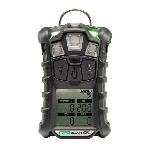
Figure 2-1. Instrument View The instrument monitors gases in ambient air and in the workplace. The ALTAIR 4X is available with a maximum of three sensors, which can display readings for four separate gases (one Two Toxic Sensor provides both CO and H 2 S sensing capabilities in a single sensor). -
Page 14: Device Hardware Interfaces
The Safe LED flashes once every 15 seconds to notify the user that the instrument is ON and operating under the conditions defined in Section 3.7. This option can be turned OFF through the MSA Link software The Alarm LEDs are visual indications of an alarm condition or any type... -
Page 15: Vibrating Alarm
2.2.4 Backlight The backlight automatically activates when any front panel button is pressed and remains ON for the duration of user-selected timeout. This ON/OFF duration can be changed through MSA Link software. 2.2.5 Horn The horn provides an audible alarm. -
Page 16: On-Screen Indicators
On-Screen Indicators 2.2.6 Graphic Symbols Gas Type Gas Concentration Alarm Symbol – No Gas Cylinder – Indicates cal Indicates alarm state gas should not be applied and instrument must be exposed to fresh air Bump Check Symbol – Hourglass – Indicates successful bump Indicates user should wait or cal... -
Page 17: Battery Life Indicator
2.2.7 Battery Life Indicator The battery condition icon continuously displays in the upper right-hand corner of the color display. As the battery is depleted, battery icon segments blank until only the battery icon outline remains. Each indicator segment represents approximately 25% of the total battery capacity. -
Page 18: Battery Shutdown
Battery Shutdown " WARNING If the battery shutdown alarm activates, stop using the instrument as it no longer has enough power to indicate potential hazards, and persons relying on this prod- uct for their safety could sustain serious personal injury or death. -
Page 19: To Charge The Instrument
To Charge the Instrument • Firmly insert the charger connector into the charge port on the back of the instrument. • The battery symbol scrolls through a progressively increasing number of segments and the charge LED is red until 90% of full charge is obtained. Then, remains fully illuminated and the charge LED turns green while the battery is trickle charged to its full capacity. -
Page 20: Peak Readings (Peak Page)
2.3.2 Peak Readings (PEAK page) The peak icon shows the highest levels of gas recorded by the instrument since turn-ON or since peak readings were reset. To reset the peak readings: 1. Access the PEAK page. 2. Press the ▲ button. 2.3.3 Minimum Readings (MIN page) This page shows the lowest level of oxygen recorded by the instrument since turn-ON or since the MIN reading was reset. -
Page 21: Stel Calculation Examples
(10 minutes x 35 PPM) + (5 minutes x 15 PPM) = 25 PPM 15 minutes This page can be de-activated through MSA Link. 2.3.5 Time Weighted Average (TWA Page) " WARNING If the TWA alarm activates, leave the contaminated area immediately;... -
Page 22: Twa Calculation Examples
8 hours 2.3.6 Time Display Current time appears on the display in a 12-hour format by default. A 24-hour format can be selected using MSA Link. 2.3.7 Date Display Current date appears on the display in the format: MM-DD-YYYY. 2.3.8 Last Cal Page Displays the instrument's last successful calibration date in the format: MM-DD-YYYY. -
Page 23: Sensor Missing Alarm
After 30 seconds of inactivity, the full Motion Alert alarm is triggered. This alarm can only be cleared by pressing the button ▲ 2.4 Sensor Missing Alarm The instrument enters the Sensor Missing alarm if the instrument detects that a sensor is not properly installed in the instrument. If a sensor is detected as missing, the following occurs: •... -
Page 24: Monitoring Oxygen Concentration
" WARNING If an alarm activates while using the instrument, leave the area immediately. Remaining in the area under such circumstances can cause serious personal injury or death. The instrument has four gas alarms for each toxic gas: • HIGH Alarm •... -
Page 25: Monitoring Combustible Gases
• a vibrating alarm triggers • instrument displays and flashes the Alarm icon and either the Minimum icon (Enriched alarm) or the Maximum icon (Deficient alarm) along with the corresponding oxygen concentration. The LOW alarm (oxygen deficient) is latching and will not automatically reset when the O 2 concentration rises above the LOW setpoint. - Page 26 When gas reading reaches 100% LEL or 5.00% CH 4 , the instrument enters a Lock Alarm state, the combustible sensor shuts down and displays “xxx” in place of the actual reading. This state can only be reset by turning the instrument OFF and ON in a fresh air environment. "...
-
Page 27: Operation
3. Operation Instrument operation is dialog driven from the display with the aid of the three Function buttons (see Section 2). 3.1. Environmental Factors A number of environmental factors may affect the gas sensor readings, including changes in pressure, humidity and temperature. Pressure and humidity changes affect the amount of oxygen actually present in the atmosphere. -
Page 28: Turning On And Fresh Air Setup
3.2. Turning ON and Fresh Air Setup Instrument operation is dialog driven from the display with the aid of the three Function buttons (see Section 2.2.1). For more information, see the flow charts in Section 7. Turn the instrument ON with the button. -
Page 29: Screen Displays During Startup
Name of Combustible Gas Type displays, e.g. BUTANE. Combustible gas type can be changed manually through the SENSOR SETUP menu or the MSA Link software. Toxic Gas Units Name of Toxic Gas Units displays (ppm or mg/m Toxic units can only be modified through the MSA Link software. -
Page 30: Alarm Setpoints
Alarm setpoints for all installed and activated sensors display. LOW alarm setpoints display, followed by HIGH alarm setpoints. Alarm setpoints can be changed manually through the Setup menu or the MSA Link software. STEL and TWA Setpoints The preset STEL and TWA values for installed and activated sensors display. -
Page 31: Last Cal Date And Cal Due
Last CAL Date and CAL Due These display options can be set by MSA Link software. If these options are not set, these screens are not displayed. • By default Last Cal is activated. • By default Cal Due is deactivated Fresh Air Setup (FAS) The FAS screen is prompted (see Section 3.2.2) -
Page 32: Measurement Mode (Normal Operation)
Figure 3-1. Fresh Air Setup If this option is enabled, the instrument displays "FAS?", prompting the user to perform a Fresh Air Setup. 1. Press the ▲ button to bypass the Fresh Air Setup. • The Fresh Air Setup is skipped •... -
Page 33: Peak Page
Peak Page This page shows the peak readings for all sensors. Min Page This page shows the minimum reading for the oxygen sensor. STEL Page This page shows the calculated STEL readings of the instrument TWA Page This page shows the calculated TWA readings of the instrument. Time / Date Page This page shows actual time and date settings of the instrument. -
Page 34: Motion Alert
2. Press button to enter the setup menus. • Incorrect password: instrument enters the Measure mode. • Correct password: instrument continues/beeps three times. The password can be changed through the MSA Link software. In the Setup mode: • Press the button to store chosen value or go to the next page. -
Page 35: Sensor Setup
• Press ▼ button to decrease values by one or toggle a selection ON or OFF. Press and hold ▼ button to decrease values by 10. The following options are available by pressing the ▼ and ▲ buttons: • Sensor Setup (SENSOR SETUP) - see Section 3.4.1 •... -
Page 36: Calibration Setup
3.4.2 Calibration Setup The user can change and set the calibration values for each sensor. It is also possible to select whether the Cal Due screen is displayed and set the number of days until the next calibration is due. For more information, see the flow charts in Section 7.7. -
Page 37: Figure 3-4. Alarm Setup
Figure 3-4. Alarm Setup 1. To bypass this setup, press the ▼ or ▲; otherwise, continue as follows. 2. Press the button to enter the submenu. 3. Set alarms ON or OFF by pressing the ▲ or ▼ button. Confirm with the button. -
Page 38: Setup Time And Date
Connecting Instrument to PC 1. Switch ON the ALTAIR 4X and align the Datalink Communication port on the ALTAIR 4X to the IR interface of the PC. 2. Use the MSA Link software to communicate with the instrument. See MSA Link documentation for detailed instructions. -
Page 39: Function Tests On The Instrument
3.6 Function Tests on the Instrument Alarm Test Turn ON the instrument. Verify that: • all LCD segments are activated momentarily • alarm LEDs flash • horn sounds briefly • vibrating alarm triggers briefly. 3.7 Safe LED The instrument is equipped with a green "SAFE LED". This green SAFE LED flashes every 15 seconds under the following conditions: •... -
Page 40: Equipment
0.25 liters/min. Flow Regulator • 1/8" ID Superthane Ester Tubing • ALTAIR 4X Calibration Cap. 3.8.2 Performing a Bump Test 1. From the normal measure screen, press the ▼ button to display "BUMP TEST?". 2. Verify the gas concentrations displayed match the Calibration Check Gas Cylinder. - Page 41 • Ensure that the calibration cap is properly seated. • Connect one end of the tubing to the calibration cap. • Connect other end of tubing to the cylinder regulator (supplied in the calibration kit). 4. Press the button to start the bump test then open the valve on the regulator.
-
Page 42: Calibration
4X Multigas Detector must be operated in the 0-5% by volume CH 4 mode and must be calibrated with 2.5% by volume methane. The ALTAIR 4X can be calibrated manually using this procedure or automatically using the Galaxy Test Stand. Refer to 7.7 of the Appendix. -
Page 43: Span Calibration
3. With the instrument exposed to fresh air, press the button to confirm the ZERO screen. A sensor Refresh and Zero Calibration now occur. NOTE: Alternatively, press the ▼ button to execute a Fresh Air setup (FAS). See section 3.2.2 for more details. •... - Page 44 • Press both side tabs down onto instrument until they snap in. • Ensure that the calibration cap is properly seated. • Connect one end of the tubing to the calibration cap. • Connect other end of tubing to the cylinder regulator (supplied in the calibration kit).
-
Page 45: Finishing Calibration
If the span calibration is unsuccessful: • a Sensor Life Indicator displays ( ) to show the sensor has reached its end of life and should be replaced • The unit remains in alarm state until the ▲ button is pressed •... -
Page 46: Maintenance
Repair or alteration of the ALTAIR 4X Multigas Detector, beyond the procedures described in this manual or by any- one other than a person authorized by MSA, could cause the instrument to fail to perform properly. Use only genuine MSA replacement parts when performing any maintenance proce- dures described in this manual. -
Page 47: Troubleshooting
ALARM and recharge battery ERROR Charge error Instrument must be between CHARGE 10 and 35°C to charge. Contact MSA if problem persists SENSOR Missing Sensor Verify sensor is properly installed ERROR and recalibrate. Contact MSA if problem persists Instrument does... -
Page 48: Adding A Sensor
4.2 Live Maintenance Procedure - Replacing and Adding a Sensor " CAUTION Before handling the PC board, the user must be properly grounded; otherwise, static charges could damage the electronics. Such damage is not covered by the warranty. Grounding straps and kits are available from electronics suppliers. - Page 49 • Insert the combustible sensor by placing it in the middle position of the sensor holder. • If any sensor is not to be installed, ensure that a sensor plug is installed properly in its place. 5. If replacing sensor filters at this time: •...
-
Page 50: Cleaning The Instrument
4.3 Cleaning the Instrument Clean the exterior of the instrument regularly using only a damp cloth. Do not use cleaning agents as many contain silicones which damage the combustible sensor. 4.4 Storage When not in use, store the instrument in a safe, dry place between 65°F and 86°F (18°C and 30°C). -
Page 51: Technical Specifications/Certifications
5. Technical Specifications/Certifications 5.1 Technical Specifications WEIGHT 7.9 oz. (instrument with battery and clip) DIMENSIONS 4.4 x 3.00 x 1.37 inches – without fastening clip (L x W x H) ALARMS Four gas alarm LEDs, a charge status LED, an audible alarm, and a vibrating alarm VOLUME OF 95 dB typical... -
Page 52: Factory-Set Alarm Thresholds And Setpoints
USA (Mining) MSHA 30 CFR Part 22, Methane Detector Europe Union The product ALTAIR 4X complies with the following directives, standards or standardized documents: Directive 94/9/EC (ATEX): II 1G Ex ia IIC T4, -40°C to +60°C, IP67 (Zone 0 with no combustible sensor installed) II 2G Ex ia d IIC T4, -40°C to +60°C, IP67... -
Page 53: Performance Specification
Performance Specification 5.4.1 Combustible Gas Range 0 to 100% LEL or 0 to 5% CH 4 Resolution 1% LEL or 0.05% vol CH 4 Reproducibility 3% LEL, 0% to 50% LEL reading or 0.15 % CH 4 , 0.00% to 2.50 % CH 4 (normal temperature range) 5% LEL, 50% to 100% LEL reading or 0.25 % CH 4 , 2.50% to 5.00 % CH 4... -
Page 54: Carbon Monoxide
5.4.3 Carbon Monoxide Range 0 - 1999 ppm CO Resolution 1 ppm CO Reproducibility ± 5 ppm CO or 10 % of reading, whichever is greater (normal temperature range) ±10 ppm CO or 20 % of reading, whichever is greater (extended temperature range) Response Time 90% of final reading... -
Page 55: Order Information
Charging Cradle Assembly with Power Supply (Australia) 10089487 Charging Cradle Assembly with Power Supply (Europe) 10086638 Vehicle Charging Cradle Assembly 10095774 MSA Link Software CD- Rom 10088099 JetEye IR Adapter with USB Connector 10082834 Combustible Sensor Replacement Kit 10106722 O 2 Sensor Replacement Kit... -
Page 56: Appendix - Flow Charts
7. Appendix – Flow Charts 7.1. Start Up Sequence (Power ON) -
Page 57: Fresh Air Setup
7.2 Fresh Air Setup... -
Page 58: Reset Screen Controls
7.3 Reset Screen Controls... -
Page 60: Bump Test
7.4 Bump Test... -
Page 61: Options Setup
7.5 Options Setup... -
Page 62: Sensor Setup
7.6 Sensor Setup... -
Page 63: Calibrations
7.7 Calibrations... -
Page 64: Alarm Setup
7.8 Alarm Setup... -
Page 65: Time And Date Setup
7.9 Time and Date Setup 7-10...
Need help?
Do you have a question about the ALTAIR 4X and is the answer not in the manual?
Questions and answers