Table of Contents
Advertisement
Thank you for purchasing the Shimaden SR60 Series. Please check that the delivered product is the
correct item you ordered. Please do not begin operating this product until you have read this instruction
manual thoroughly and understand its contents.
Please ensure that this instruction manual is given to the final user of the instrument.
This instruction manual is meant for those who will be involved in the wiring, installation, operation and routine maintenance of the SR60
series (SR62, SR63, and SR64).
This manual describes the care, installation, wiring, function, and proper procedures for the operation of SR60 (SR62, SR63, SR64) series.
Keep this manual at the work site during operation of the SR60 series. While using this instrument, you should always follow the
guidance provided herein.
1. The Matters regarding Safety.....................................................................................................................................................................2
2. Specifications .............................................................................................................................................................................................3
3. Introduction................................................................................................................................................................................................5
3-1.
Check before Use ..........................................................................................................................................................................5
3-2.
Handing Instruction .......................................................................................................................................................................5
4. Installation and Wiring...............................................................................................................................................................................5
4-1.
Installation Site..............................................................................................................................................................................5
4-2.
Mounting .......................................................................................................................................................................................5
4-3.
How to Take the Controller out of the Case..................................................................................................................................5
4-4.
External Dimensions and Panel Cutout.........................................................................................................................................5
4-5.
Wiring............................................................................................................................................................................................6
4-6.
Terminal Layout ............................................................................................................................................................................6
4-7.
Terminal Arrangement Table ........................................................................................................................................................6
5. Names and Functions of Parts....................................................................................................................................................................6
6. Parameter Operating Procedure, Flow, and Functions ..............................................................................................................................7
6-1.
Operating Procedure......................................................................................................................................................................7
6-2.
Parameter Flow and Functions ......................................................................................................................................................8
7. Operation..................................................................................................................................................................................................10
7-1.
Power ON and Initial Screen Display .........................................................................................................................................10
7-2.
7-3.
Measuring Range Scaling "Mode 2-2" (For voltage or current input)........................................................................................11
7-4.
7-5.
Setting of alarm action point "Mode 0-2/0-3" (Optional) ...........................................................................................................12
7-6.
Execution of Auto Tuning (AT) Action ......................................................................................................................................12
7-7.
7-8.
Setting of Set Value Bias (Sb) "Mode 0-5" (Optional) ...............................................................................................................13
7-9.
Setting of Current Values for Heater Break and Heater Loop Alarms (Optional) .....................................................................13
7-10.
7-11.
Automatic Return of Display Screen...........................................................................................................................................14
8. Error Messages.........................................................................................................................................................................................14
8-1.
Problems with Process Value Input.............................................................................................................................................14
8-2.
Problems with CT Input for Heater Break Alarm (HB) ..............................................................................................................14
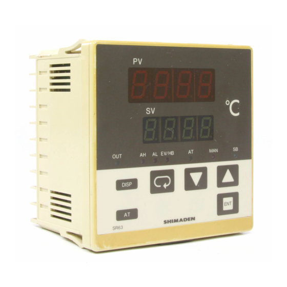
SR60 (SR62, 63, 64) Series
Digital Controller
Instruction Manual
Notice
Preface
Contents
SR60F-1EJ/E jun. 2000
Advertisement
Table of Contents

Related Manuals for Shimaden SR62


Summary of Contents for Shimaden SR62
-
Page 1: Table Of Contents
(SR62, SR63, and SR64). This manual describes the care, installation, wiring, function, and proper procedures for the operation of SR60 (SR62, SR63, SR64) series. Keep this manual at the work site during operation of the SR60 series. While using this instrument, you should always follow the guidance provided herein. -
Page 2: The Matters Regarding Safety
1. The Matters regarding Safety CAUTION For matters, regarding safety, potential damage to equipment and/or • Fuse: Since the instrument does not have a built-in fuse, do not facilities, additional instructions are indicated by the following headings: forget to install a fuse in the power circuit to be connected to the WARNING power terminal. -
Page 3: Specifications
2. Specifications Control • Control mode: Auto-tuning PID Display Proportional band (P): Off, 0.1~999.9% FS (Off setting: On-Off • Digital display: 7 segments / Measured value (PV) action) Red LED 4 digits, Set value (SV) Integral time (I): 1~6000 sec. Green LED 4 digits (Off setting: PD, P action) ±... - Page 4 On time: 250 msec. minimum drip-proof structure • Alarm output / rating: Contact 1a / 240V AC 1.5A (resistive load) • Material: PPO resin molding (equivalent to UL94V-1) SR62: H72 × W72 × D110 • Alarm holding: Selectable • External dimensions: • Sampling cycle: 0.5 sec.
-
Page 5: Introduction
Item Code and Description (4) Where highly intense vibration or impact is generated or transferred. 1. Series SR62, SR63, SR64 (5) Near high voltage power lines or where inductive interference can 2. Input 1: Thermocouple 2. R.T.D. 3. Voltage (mV) affect the operation of the product. -
Page 6: Wiring
WARNING Terminal No. Description Name of terminal • When wiring, make sure to disconnect the power supply. SR62 SR63 SR64 Otherwise an electric shock may result. Power supply 100-240V AC, 24V DC, or 24V AC 8-9 11-12 11-12 terminal •... -
Page 7: Parameter Operating Procedure, Flow, And Functions
Display Section 6. Parameter Operating Procedure, Flow, and Functions Process value (PV) display / red 6-1. Operating Procedure Process values (PV) are displayed. When a parameter is set, its (Parameter Flow and Functions are shown in section 6-2.) type is displayed. When something goes out of order in the system, an error message (1) Turn on the power supply to display the "Mode 0-0"... -
Page 8: Parameter Flow And Functions
6-2. Parameter Flow and Functions Function selection mode Parameter setting mode for operation Mode 2 Mode 0 Press for 5 seconds. DISP Press for 3 seconds. Basic screen Values set Mode Item Setting range when shipped Setting of set value Within measuring range 0 Unit or PV/SV... - Page 9 mode 1 Setting range Name of screens Numbers in ( ) shows Function description and mode No. values set before shipping For the quick selection of a desired parameter, set the parameter mode Direct call execution 1~18 No., the desired parameter No. out of 1 through 18 on the SV display of screen the "Mode 1-0"...
-
Page 10: Operation
7. Operation Basic screen 7-1. Power ON and Initial Screen Display Press for 5 seconds. DISP When power is supplied, a selected function is displayed on the screen as Selection of measuring range, shown below. Then, in about 3 seconds, the "Mode 0-0" basic screen is Function selection control system, alarm, event, screen... -
Page 11: Measuring Range Scaling "Mode 2-2" (For Voltage Or Current Input)
• Indication No. Selection of Output Action Characteristics • Indication No. Selection of Analog Output Type (Optional) (selection between RA / DA) (P/S) Either of the control output action characteristics, DA (direct action) (P): Process value (PV) output (Initial value) or RA (reverse action), is set. -
Page 12: Setting Of Set Value "Mode 0-0
• Operating procedure 7-4. Setting of set value "Mode 0-0" (1) Press the key in the basic screen during operation to establish (1) After supplying power, confirm that the "Mode 0-0" basic screen is auto tuning standby condition. Then, the AT lamp lights up. displayed. -
Page 13: Operation By Manual Control "Mode 0-1
7-7. Operation by Manual Control "Mode 0-1" 7-8. Setting of Set Value Bias (Sb) "Mode 0-5" (Optional) Changing to manual control mode If a bias amount is previously set in the set set value, the initial set set value added with the bias amount makes a set value when the SB Changing to control output manual mode and setting of manual control terminals go on (short circuited). -
Page 14: Operation Of Keylock ( ) "Mode 1-18
8. Error Messages • Selection of heater break alarm output mode 8.1 Problems with Process Value Input Process value (PV) The control output upon sensor detection of abnormality becomes 0% regardless its characteristics. : Lock mode Set value (SV) : Real mode Thermocouple has burnt out, A of R.T.D has burnt out, PV value exceeds the higher limit of Use the...
Need help?
Do you have a question about the SR62 and is the answer not in the manual?
Questions and answers