Table of Contents
Advertisement
Quick Links
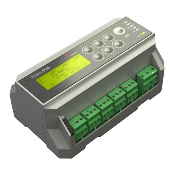
MainsPro
Mains Decoupling Protection Relay
Comprehensive Guide
SW version 1.4, January 2013
Copyright © 2013 ComAp a.s.
Written by Petra Piclova
Prague, Czech Republic
Installation and Operation Guide
ComAp a.s.
Kundratka
2359/17, 180 00 Praha 8, Czech Republic
Tel: +420
246 012
111, Fax: +420 246 316 647
E-mail: info@comap.cz, www.comap.cz
Application Guide
Reference Guide
Advertisement
Chapters
Table of Contents

Related Manuals for ComAp MainsPro

Summary of Contents for ComAp MainsPro
- Page 1 Comprehensive Guide SW version 1.4, January 2013 Installation and Operation Guide Application Guide Reference Guide ComAp a.s. Copyright © 2013 ComAp a.s. Kundratka 2359/17, 180 00 Praha 8, Czech Republic Written by Petra Piclova Tel: +420 246 012 111, Fax: +420 246 316 647 Prague, Czech Republic E-mail: info@comap.cz, www.comap.cz...
-
Page 2: Application Guide
Though MainsPro is very simple and intuitive for the operating personnel, we recommend keeping one copy of this manual available permanently at the site where MainsPro unit is installed, to facilitate the necessary service and operation tasks. - Page 3 Mains Decoupling Protection Relay Installation and Operation Guide SW version 1.4, January 2013 Installation and Operation Guide ComAp a.s. Copyright © 2013 ComAp a.s. Kundratka 2359/17, 180 00 Praha 8, Czech Republic Written by Petra Piclova Tel: +420 246 012...
-
Page 4: Table Of Contents
Reset trip counters ........................14 TEST mode activation ........................15 Factory default ..........................15 Mechanical sealing ..........................15 Signalization LEDs ..........................15 Measurement screens ........................17 Alarm messages ..........................19 MainsPro, SW version 1.4, ©ComAp – January 2013 MainsPro Installation and Operation Guide... -
Page 5: Introduction
Though MainsPro is very simple and intuitive for the operating personnel, we recommend keeping one copy of this manual available permanently at the installation site, where MainsPro unit is installed, to facilitate the necessary service and operation tasks. -
Page 6: Warnings
To avoid personal injury do not perform any action not specified in this guide!!! Note: ComAp believes that all information provided herein is correct and reliable and reserves the right to update at any time. ComAp does not assume any responsibility for its use unless otherwise expressly undertaken. -
Page 7: Installation Data
Installation data Dimensions MainsPro, SW version 1.4, ©ComAp – January 2013 MainsPro Installation and Operation Guide... -
Page 8: List Of Terminals
MainsPro Frame MainsPro Frame is a MainsPro accessory product, allowing door-mounting of the unit, direct access to the keyboard and the screen without opening the switchboard, and additional shielding (IP 55) for the front panel. The frame size is 230x180x34 mm. -
Page 9: Wiring
230 V system and 156 V for 120 V system with no change of measurement accuracy. “Delta” connection In this arrangement, MainsPro is rated for 400 VAC ph-ph with over-range to 130% = 520 VAC with no change of measurement accuracy. Setpoint... -
Page 10: Connection With Voltage Transformers
Power supply MainsPro provides set of 3 terminals for the purpose of dual power supply range: 8 - 40 VDC: use the terminals + and N/- 85 - 265 VAC / 110-370 VDC: use the terminals L/+and N/-... -
Page 11: Relay Outputs Connection
Relay outputs connection For safety purposes, it is recommended to set all MainsPro relay outputs to inverse logic for failure trips and signalling. This means that under fault-free conditions all contacts are kept in energized position. -
Page 12: Binary Switches Connection
Basic: Uin to 120V. Wiring examples This chapter provides examples of possible wiring of MainsPro which can be used as a preparation concept of wiring scheme. Note: ComAp bears no responsibility of functionality of the solution where these concepts are applied. - Page 13 (12) close and the voltage is applied on the Off coil, therefore auxiliary power supply (e.g.UPS) is necessary to provide voltage for the Off coil. MainsPro, SW version 1.4, ©ComAp – January 2013 1-11 MainsPro Installation and Operation Guide...
- Page 14 3. Under normal conditions the contacts are closed, in case of failure the contacts open. This wiring is typically used for coil driven contactors. MainsPro, SW version 1.4, ©ComAp – January 2013 1-12 MainsPro Installation and Operation Guide...
-
Page 15: User Interface
The setpoint groups are displayed in the cycling order, i.e. from the last setpoint group by button , the cursor moves to the first group and vice versa. MainsPro, SW version 1.4, ©ComAp – January 2013 1-13 MainsPro Installation and Operation Guide... -
Page 16: Reset Operation Time
By selecting YES, all trip counters will be reset. Press to confirm your selection. 4. By selecting NO and pressing or by pressing , return to the measurement screens with no change. MainsPro, SW version 1.4, ©ComAp – January 2013 1-14 MainsPro Installation and Operation Guide... -
Page 17: Test Mode Activation
Mechanical sealing MainsPro allows to mechanically prevent the setting changes by securing the mechanical seal in locked position by sealing wire. The locked position is indicated at the MainsPro side-print and on the alphanumerical display. Signalization LEDs There are 7 LEDs for indication of MainsPro status with the meaning indicated in the table below: In case of signalling different statuses by one LED, the following priorities apply, i.e. - Page 18 Vector shift nor ROCOF protections are not enabled by setpoint and no other indicated failure is sensed Indication of severe internal failure. Contact ComAp technical Status flashing support! MainsPro, SW version 1.4, ©ComAp – January 2013 1-16 MainsPro Installation and Operation Guide...
-
Page 19: Measurement Screens
Negative sequence overvoltage and positive sequence undervoltage are methods of evaluation of angle asymmetry of the 3-phase voltage system. See more in the chapter Voltage unbalance and angle asymmetry MainsPro, SW version 1.4, ©ComAp – January 2013 1-17 MainsPro Installation and Operation Guide... - Page 20 Time measurement screen: : time since MainsPro was powered Operation Time Last Trip Time: time of the latest trip since MainsPro was powered-up Please note that the time information on the MainsPro unit is not measured by a calibrated RTC device and may serve for orientation purposes only.
-
Page 21: Alarm Messages
Vneg Negative sequence overvoltage Vpos Positive sequence undervoltage Vavg 10 minutes floating average overvoltage Wrong phase rotation Wrong polarity of one phase External trip Start Trip MainsPro, SW version 1.4, ©ComAp – January 2013 1-19 MainsPro Installation and Operation Guide... - Page 22 MainsPro Mains Decoupling Protection Relay Application Guide SW version 1.4, January 2013 Application Guide ComAp a.s. Copyright © 2013 ComAp a.s. Kundratka 2359/17, 180 00 Praha 8, Czech Republic Written by Petra Piclova Tel: +420 246 012 111, Fax: +420 246 316 647 Prague, Czech Republic E-mail: info@comap.cz, www.comap.cz...
- Page 23 Table of contents ..........................2 Purpose of this manual ........................3 MainsPro typical usage ........................3 Typical applications of MainsPro protection relay ................3 Important Steps of MainsPro utilization ....................4 TRIP and Fault Reset description ....................... 5 TRIP ..............................5 Fault reset ............................
-
Page 24: Purpose Of This Manual
Purpose of this manual The Application Guide serves for the designers and engineers, who process the necessary documentation and implementation procedures on the installation site, where MainsPro is installed. It contains detailed description of MainsPro functionalities its practical application. MainsPro typical usage MainsPro is a mains protective relay protecting operation of parallel-to-mains generators or other electrical resources of distributed generation of electricity. -
Page 25: Important Steps Of Mainspro Utilization
Important Steps of MainsPro utilization This process describes a typical decisions and technical steps to follow in case of MainsPro utilization, if required by the distribution network operator (DNO). Does the DNO require a mains- Request the protection unit? If required protection yes, then... -
Page 26: Trip And Fault Reset Description
I.e., the unit may not be „provisionally“ fault- reset. By a successful Fault reset, the TRIP status is terminated. MainsPro, SW version 1.4, ©ComAp – January 2013 MainsPro Application Guide... -
Page 27: Protective Features
Protective features The following protective functionalities, referred also by their ANSI number, are available in MainsPro unit: ANSI 59 Overvoltage, ANSI 27 Undervoltage The RMS value of measured voltage is compared with the preset limit of overvoltage or undervoltage. When any of the preset limits is over/underreached, the appropriate LED signal is issued by... -
Page 28: Vector Shift
Picture 2: decomposition of a generic 3-phase voltage to symmetrical components MainsPro provides positive and negative sequence voltage evaluation and compares the measured values with V> neg V< pos thresholds. In the perfectly symmetrical arrangement, negative sequence voltage is zero and positive sequence voltage equals to the measured voltage. - Page 29 As shown in the timing diagram the voltage jumps to another value and the phase position changes. This procedure is called phase or vector surge. MainsPro continuously measures the cycles, starting each zero up ward slope. The time cycle is internally compared to the reference time. In case of vector surge the zero up ward is delayed and the device trips instantaneously.
-
Page 30: Rate Of Change Of Frequency (Rocof)
81R Rate Of Change Of Frequency (ROCOF) ROCOF is another fast "Loss of Mains" protection stages provided in MainsPro. It is based on the similar principle as Vector shift, i.e. dependence of the generator speed and voltage on the load size. -
Page 31: Counters
Basic. External trip In case that a specific protective function is requested and this function is not supported in MainsPro, it may be provided in an external device. Wire the output of this device to Ext binary switch to allow tripping by this external device. -
Page 32: Test Mode
The purpose of this functionality is to allow automatic delayed return to mains in case that the mains is completely lost and MainsPro unit is powered from the same mains voltage. TEST mode MainsPro provides a TEST mode, which enables phase-to-phase testing of 3-phase protective features by single-phase power source. - Page 33 MainsPro Mains Decoupling Protection Relay Reference guide SW version 1.4, November 2012 Reference Guide ComAp a.s. Copyright © 2013 ComAp a.s. Kundratka 2359/17, 180 00 Praha 8, Czech Republic Written by Petra Piclova Tel: +420 246 012 111, Fax: +420 246 316 647 Prague, Czech Republic E-mail: info@comap.cz, www.comap.cz...
- Page 34 CommTrpPer ............................. 12 !CommTrpPer ............................ 12 CommTrpImp ............................ 12 !CommTrpImp ........................... 12 CommSigImp............................. 12 !CommSigImp............................ 13 CommSigDel ............................. 13 !CommSigDel ............................ 13 U Sig ..............................13 !U Sig ..............................13 MainsPro, SW version 1.4, ©ComAp – January 2013 MainsPro Reference Guide...
- Page 35 Loss of Mains reaction times ......................18 Technical parameters ........................19 Endurance to the power supply voltage fails ................19 Statement of the factory default setting of MainsPro unit ..............20 MainsPro, SW version 1.4, ©ComAp – January 2013 MainsPro Reference Guide...
-
Page 36: Purpose Of This Manual
The Reference Guide contains library of setpoints, inputs and outputs functionalities and technical data for the purpose of detailed technical information. This information is referenced in the Installation and Operation Guide and Application Guide. MainsPro, SW version 1.4, ©ComAp – January 2013 MainsPro Reference Guide... -
Page 37: Library Of Setpoints
Library of setpoints MainsPro provides the possibility of dual setting of the protection functions setpoints. This setting may be used in case that the installation is running in exceptional conditions with different requirements for protections setting. Some groups of setpoints have their alternative setpoints identified by the same name, but with latter “A.”... -
Page 38: Imp Len [S]
Threshold of 1st and 2nd stage overvoltage, and 1st and 2nd stage undervoltage protection, respectively. Range: 1..999 V 0 = OFF, the appropriate stage of voltage protection is not enabled Default setting: MainsPro, SW version 1.4, ©ComAp – January 2013 MainsPro Reference Guide... -
Page 39: V> Del, V>> Del, V< Del, V<< Del [S]
0..999 V 0 = OFF, the amplitude asymmetry is disabled Default setting: 0 = OFF V< pos, A.V< pos [V] Threshold of the positive sequence undervoltage (angle asymmetry method). MainsPro, SW version 1.4, ©ComAp – January 2013 MainsPro Reference Guide... -
Page 40: V> Neg, A.v> Neg [V]
Frequency level at which the protection activates again after a trip caused by underfrequency. The TRIP status will be terminated. Range: 100,0 - 110,0 %f< 0 = OFF, the reset threshold is not activated Default setting: 100,0 %f< MainsPro, SW version 1.4, ©ComAp – January 2013 MainsPro Reference Guide... -
Page 41: Lom, A.lom
CB Fdb Not used (for the possibility if none of the defined BI is assigned) Default setting: - BI1: Ext - BI2: F.R. - BI3: Alt - BI4: Dis MainsPro, SW version 1.4, ©ComAp – January 2013 MainsPro Reference Guide... -
Page 42: F(Re)
LOM Sig !LOM Sig dU Sig !dU Sig Other Sig !Other Sig TrpEndImp InternFail BakTrpPer BakTrpImp Default setting: RE1: !CommTrpPer RE2: CommTrpImp RE3: BakTrpImp RE4: !InternFail RE5: TrpEndImp MainsPro, SW version 1.4, ©ComAp – January 2013 3-10 MainsPro Reference Guide... -
Page 43: Library Of Binary Switches
In this case, the unit does not trip on any fault conditions. CB Feedback Deactivation of this switch confirms opening of the circuit breaker after a trip is issued by MainsPro. If the feedback does not confirm opening of the CB, additional back-up trip... -
Page 44: Library Of Relay Outputs
Library of relay outputs The standard logic of MainsPro corresponds to the standard of protective relays and offers an option to set the logic of the relay outputs. For safety reasons there are available full set of outputs marked with an exclamation mark “!”, which remain energized in fault-free state and in case of power supply failure, the unit goes to “fault”... -
Page 45: Commsigimp
If the relay is open during trip activation, it closes no sooner than Basic: Imp Len since trip status activation. Fault reset has no influence on this output. If MainsPro, SW version 1.4, ©ComAp – January 2013 3-13... -
Page 46: Lom Sig
Impulse at the end of the TRIP state. The output is normally activated during operation of the unit. The output deactivates at the end of the TRIP state (i.e. after successful Fault Reset is performed) for period given by the parameter Len. MainsPro, SW version 1.4, ©ComAp – January 2013 3-14 MainsPro Reference Guide... -
Page 47: Internfail
Len. Opening of the relay does not mean end of trip state. The trip is terminated in fault free state after a successful fault reset. During trip status, the relay does not react on any new failure MainsPro, SW version 1.4, ©ComAp – January 2013 3-15... - Page 48 During trip status, the relay does not react on any new failure and also, if the CB Feedback input or Bak Trp output are not configured on any physical input or output, this function is blocked. MainsPro, SW version 1.4, ©ComAp – January 2013 3-16 MainsPro Reference Guide...
-
Page 49: Technical Data
3 phases is within the green area on the picture below. Outside of the green area, MainsPro provides the expected performance (i.e. trips in case of voltage overreaching the green area border), but the behaviour, accuracies and reaction times may not be guaranteed. -
Page 50: Voltage Measurement
The maximum tolerance of the unit timing is ≤3% ± 15ms. Loss of Mains reaction times Reaction time of Vector shift protection is 1,5 period of measured signal + 15 ms MainsPro, SW version 1.4, ©ComAp – January 2013 3-18 MainsPro Reference Guide... -
Page 51: Technical Parameters
Endurance to the power supply voltage fails MainsPro unit withstands the power supply voltages failures of 100 ms lengths in the full range of power supply voltage on the 85 - 265 VAC / 110 - 370 VDC terminals and at the voltage .18 - 40 VDC connected to the 8 - 40 VDC terminals. -
Page 52: Statement Of The Factory Default Setting Of Mainspro Unit
Vs Lim 0 (OFF) ROCOF limit ROCOF 0 (OFF) 0,01 [Hz/s] ROCOF filter ROCOF Filt Delay of Vector shift and ROCOF evaluation LOM Init Del after measured voltage connection MainsPro, SW version 1.4, ©ComAp – January 2013 3-20 MainsPro Reference Guide... - Page 53 MainsPro Reference Guide for information about the setpoints adjustment. ComAp states that the mentioned setting is guaranteed for all MainsPro units, SW version 1.4, upon shipment of a new unit, if no other setting is explicitly requested. In case of need, the factory default settings can be provided by the following procedure: 1.
Need help?
Do you have a question about the MainsPro and is the answer not in the manual?
Questions and answers