
Summary of Contents for TOMARK Viper SD-4 RTC
-
Page 1: Preceding
TOMARK, s.r.o. Airplane Maintenance Manual Preceding Pages Viper SD-4 RTC Airplane Maintenance Manual Doc. N° TOM-TC-01-AMM Issue: 04.APR 2016 Page 1... - Page 2 TOMARK, s.r.o. Airplane Maintenance Manual Intentionally left blank Chapter 00 Preceding Pages Page 2 Issue: 11.AUG 2016 Issue: 04.APR 2016...
- Page 3 TOMARK, s.r.o. Airplane Maintenance Manual Amendments Issue Date Revised Description pages Edition 1 04.APR 2016 First issue Revision 1 11.AUG 2016 3, 5, 7-17, 24, Chapter 05-50-02 and 51-60 29, 58, 66- added, editorial changes Revision 2 15.FEB 2017 3, 104, 109, AD&C-DC-58-003...
- Page 4 TOMARK, s.r.o. Airplane Maintenance Manual List of Service Bulletins SB No Date Title Affected Serial no.’s (EASA) Chapter 00 Preceding Pages Page 4 Issue: 11.AUG 2016 Issue: 04.APR 2016...
- Page 5 TOMARK, s.r.o. Airplane Maintenance Manual List of Effective Pages Page ..............Page date 1 .. 2 ............. 04.APR 2016 3 ..............28.FEB 2017 4 ..............04.APR 2016 5 ..............28.FEB 2017 6 ..............04.APR 2016 7 .. 9 ............11.AUG 2016 10 ..
-
Page 6: Table Of Contents
TOMARK, s.r.o. Airplane Maintenance Manual Table of Contents Chapter Title ................... Page Preceding Pages ............1 00-10 List of Figures ..............14 Introduction ............16 01-00 General ................16 01-10 Coverage ................16 01-20 Guidelines ................16 01-30 Related Publications ............. 17 01-40 Addresses ................ - Page 7 TOMARK, s.r.o. Airplane Maintenance Manual 04-30-20 Major Inspection Engine Mount ............. 26 04-40 Software ................27 Inspection and Maintenance ........28 05-00 General ................28 05-10 Time Limits and Inspection Program ........28 05-10-01 Component Time Limits ..............29 05-20 Scheduled Maintenance ............
- Page 8 TOMARK, s.r.o. Airplane Maintenance Manual 06-10-05 Flap ....................71 06-10-06 Horizontal Tail ................71 06-10-07 Elevator ..................71 06-10-08 Elevator Trim Tab ................71 06-10-09 Vertical Tail ................... 71 06-10-10 Rudder ..................72 06-10-11 Fuel System ................... 72 06-10-12 Landing Gear ................. 72 06-10-13 Propeller ..................
- Page 9 TOMARK, s.r.o. Airplane Maintenance Manual Air Conditioning ........... 91 21-20 Distribution ................91 21-40 Heating ................92 Electrical Power ............ 94 24-00 General ................94 24-30 DC Generation ..............94 24-30-10 Generator ..................94 24-30-20 Battery ..................94 24-30-30 Signaling ..................95 24-60 Distribution ................
- Page 10 TOMARK, s.r.o. Airplane Maintenance Manual 27-50 Flap System ................ 110 27-50-01 Flap ..................... 111 Fuel ..............113 28-10 Storage ................115 28-10-01 Drain Valve .................. 115 28-20 Distribution ................ 115 28-40 Indication ................115 Indication & Recording Systems ......116 31-00-01 Panel ...................
- Page 11 TOMARK, s.r.o. Airplane Maintenance Manual 33-02 Landing Light ................133 Navigation ............135 Standard Practices Structure ........ 136 51-00-00 Access Hatches, Covers and Fairings ........... 136 51-00-01 Access Hatch ................138 51-60 Control Surface Balancing ........... 139 51-70 Repair ................144 51-71 Repair of Metal Skins ............
- Page 12 TOMARK, s.r.o. Airplane Maintenance Manual 55-40 Rudder ................167 Wing ..............168 57-10 Center Wing ............... 169 57-10-01 Wing Root Fairing ................ 169 57-30 Wing Tips ................170 57-30-01 Wing Tip Fairing ................170 57-50 Flaps .................. 170 57-60 Ailerons ................170 Propeller .............
- Page 13 TOMARK, s.r.o. Airplane Maintenance Manual 75-40 Indicating ................178 75-40-01 Coolant Temperature ..............178 Oil ..............179 79-10 Storage ................179 79-10-01 Oil Tank ..................179 79-20 Distribution ................ 179 79-20-01 Oil Gear Pump ................179 79-20-02 Oil Radiator ................. 180 79-20-03 Oil Filter ..................
-
Page 14: List Of Figures
TOMARK, s.r.o. Airplane Maintenance Manual 00-10 List of Figures Figure 1 View ....................23 Figure 2 Drain holes areas ................56 Figure 3 Measuring Sections ................68 Figure 4 Measuring Points Identification ............69 Figure 5 Ventilation scheme diagram ............91 Figure 6 Heating System ................ - Page 15 TOMARK, s.r.o. Airplane Maintenance Manual Figure 38 Avionics instrument interconnection ..........188 Figure 39 On board electric power net ............189 Figure 40 FR Power supply for control stick and elevator/aileron trim ... 190 Figure 41 FU3 power supply for fuel pump ........... 191 Figure 42 FU2 power supply for SV-EMS220 module and EMS display ...
-
Page 16: Introduction
This Maintenance Manual provides educated maintenance staff information necessary for servicing, maintenance and repair of the Viper SD-4 RTC Type aircraft. It contains a detailed description of systems including time limits for the particular components and instructions for the performance of inspections and maintenance. -
Page 17: Related Publications
01-30 Related Publications NOTE The Viper SD-4 RTC is approved by a Restricted Type Certicate. The vendor data/publications can be used only if agreed for use by TOMARK In case a type certified engine ROTAX 912 S is installed to the aircraft the publications of Rotax remain applicable. -
Page 18: Addresses
TOMARK, s.r.o. Airplane Maintenance Manual 01-40 Addresses Contact: Company Address TOMARK, s.r.o. TOMARK, s.r.o., Aero division Strojnícka č.5, 080 01 Prešov Slovak republic sales@tomarkaero.com ROTAX AIRCRAFT ENGINES Refer to Rotax Service network Chapter 01 Introduction Page 18 Issue: 04.APR 2016... -
Page 19: How To Use The Manual
TOMARK, s.r.o. Airplane Maintenance Manual How to Use the Manual 02-00 General The format and contents of this manual have been prepared in accordance with the GENERAL AVIATION MANUFACTURERS ASSOCIATION (GAMA) Specification No. 2. The content of this manual is organized in three levels: Group ... -
Page 20: Notes
TOMARK, s.r.o. Airplane Maintenance Manual When a subsystem is further divided into units, a third element is added to the number sequence, e.g. 53-20-01 The table of content lists only those chapter numbers which are used in this supplement. 02-10... -
Page 21: Terminology And Abbreviations
TOMARK, s.r.o. Airplane Maintenance Manual 02-20 Terminology and Abbreviations Term Meaning AHARS Airborne Heading-Attitude Reference System Airplane Flight Manual Angle Of Attack Air Traffic Control Center of gravity EFIS Electronic Flight Instrument System Exhaust Gas Temperature Engine Monitoring System Left Hand... -
Page 22: Safety
TOMARK, s.r.o. Airplane Maintenance Manual 02-40 Safety ▶ Do not begin any work before completely having read and understood the contents of this manual and related instructions. ▶ Wear ventilated protective clothing, protective goggles, chemical resistant gloves and respiratory mask when working with solvents or in dusty conditions. -
Page 23: General Description
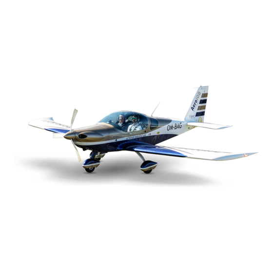
TOMARK, s.r.o. Airplane Maintenance Manual General Description 03-00 General The Viper SD-4 RTC is a low-wing, aerodynamically controlled, single-engine, two-seat with side-by-side configuration, fixed tricycle landing gear with steerable nose wheel, all-metal airplane. Figure 1... -
Page 24: Limitations
04-10 Structural Limitations and Inspection Intervals The airframe of the Viper SD-4 RTC is limited to 6000h, the engine mount to 4000h. In addition, the airframe must undergo a major airframe inspection according to 04-30 at 2000h/10year (whichever comes first) intervals both for the airframe and the engine. -
Page 25: Placards
TOMARK, s.r.o. Airplane Maintenance Manual 04-20 Placards For Markings and Placards refer to Viper SD-4 RTC Aircraft Flight Manual, Section 2, Document N°: TOM-TC-01-AFM. 04-30 Major Inspection 04-30-10 Major Inspection Airframe The major airframe inspection program is not defined at time of print. -
Page 26: Major Inspection Engine Mount
Perform dye penetrant check at all welding nodes and all identified top ○ coat crack locations. In case of doubt remove top coat at entire node. ○ If cracks are found report to TOMARK before proceeding ○ Chapter 04 Limitations Page 26 Issue: 04.APR 2016... - Page 27 TOMARK, s.r.o. Airplane Maintenance Manual Major Inspection engine mount 2000h Finish Refinish top coat at weld nodes as required. Touch up top coat at all other ○ identified scratches Reinstall engine (if removed) ○ Make appropriate airplane log book entry for release to further service ○...
-
Page 28: Inspection And Maintenance
This chapter contains charts, tables and checklists for time limits, scheduled and unscheduled maintenance, to enable licensed personnel to carry out correct inspections on the Viper SD-4 RTC aircraft. The periodic inspections and checks described and the related intervals are minimum required for maintaining the aircraft in airworthy condition. -
Page 29: Component Time Limits
TOMARK, s.r.o. Airplane Maintenance Manual Unless stated otherwise the inspection methods follow standard practice and are mainly visual. However specific attention shall be paid to the elements listed in section 04-30-10. In case of doubt perform dye penetrant inspections at the welding connections and highly stressed areas as indicated in the inspection list. -
Page 30: Scheduled Maintenance
Airplane Maintenance Manual 05-20 Scheduled Maintenance 05-20-01 Scheduled Inspection Plan Scheduled Inspection Report Type Model Serial Number Registration Viper SD-4 Viper SD-4 RTC Owner Date Type of Inspection Airframe time (logbook) 100 h/ Scheduled Inspection (50 h) annual specified Preparatory Activities Review of aircraft logbook ○... - Page 31 TOMARK, s.r.o. Airplane Maintenance Manual 100 h/ Scheduled Inspection (50 h) annual specified Clean exterior of aircraft as required, pay attention to any ○ ○ ○ unusual surface condition. Vacuum clean aircraft interior as required. ○ ○ ○ Ensure the entire aircraft is clean.
- Page 32 TOMARK, s.r.o. Airplane Maintenance Manual 100 h/ Scheduled Inspection (50 h) annual specified Oil System Check oil thermostat for proper attachment. Inspect for ○ ○ ○ leakage. Inspect oil breather line for proper routing, internal accumulation of oil/water emulation, and clogging. Clean as ○...
- Page 33 TOMARK, s.r.o. Airplane Maintenance Manual 100 h/ Scheduled Inspection (50 h) annual specified Visually check the condition and attachment of the expansion ○ ○ tank on the firewall. Fuel System Visually check the condition of the fuel hoses, connection of the fuel hoses, their attachment and tightening.
- Page 34 TOMARK, s.r.o. Airplane Maintenance Manual 100 h/ Scheduled Inspection (50 h) annual specified Inspect battery isolation provisions. ○ ○ ○ Cabin Heat System Inspect hoses for attachment, leaks and wear. ○ ○ Inspect air scoop at radiator for cleanness ○...
- Page 35 TOMARK, s.r.o. Airplane Maintenance Manual 100 h/ Scheduled Inspection (50 h) annual specified Inspect propeller mounting for security of installation. ○ ○ Inspect propeller blades for cracks, dents, nicks, scratches, ○ ○ erosion or other damage. The propeller must have a major overhaul by NEUFORM.
- Page 36 TOMARK, s.r.o. Airplane Maintenance Manual 100 h/ Scheduled Inspection (50 h) annual specified Inspect nose gear steering push-pull rods and their 05-20-02 attachment. Lubricate rod ends as per Section ○ Lubrication Chart Demount the nose gear strut fairing. ○ Visually check the nose gear strut fairing for cracks and other ○...
- Page 37 TOMARK, s.r.o. Airplane Maintenance Manual 100 h/ Scheduled Inspection (50 h) annual specified Check the tightening of the bolts and their locking. ○ ○ Check the attachment of the legs to the aeroplane’s fuselage for possible play by moving a leg forward and backward, up ○...
- Page 38 TOMARK, s.r.o. Airplane Maintenance Manual 100 h/ Scheduled Inspection (50 h) annual specified Finish Check park brake action. (brake lock must allow no slip of ○ ○ aircraft at 100% max power) Reinstall the main wheel fairings after the inspection of the ○...
- Page 39 TOMARK, s.r.o. Airplane Maintenance Manual 100 h/ Scheduled Inspection (50 h) annual specified Ailerons Visually check the condition of the ailerons. The condition of ○ ○ the skin and riveting. Check the free movement of the ailerons. ○ ○ Check the torque and locking of the aileron push-pull control ○...
- Page 40 2000h/ Perform Major inspection according to 15years Canopy Visually check the canopy for cracks, scratches and other damage. In case of crack detection contact TOMARK Aero for ○ ○ instructions. Check the condition of all attachments of the canopy. ○...
- Page 41 TOMARK, s.r.o. Airplane Maintenance Manual 100 h/ Scheduled Inspection (50 h) annual specified Horizontal stabilizer Demount the fuselage tail fairing. Reinstall the fairing only ○ ○ after the completion of the inspection. Visually check the fuselage tail fairing for cracks and other ○...
- Page 42 TOMARK, s.r.o. Airplane Maintenance Manual 100 h/ Scheduled Inspection (50 h) annual specified 05-20-02 Lubricate according to the lubrication plan ○ Lubrication Chart Check the connection of the elevator controls. 500h/ 5 years Vertical Stabilizer Visually check the condition of the vertical stabiliser.
- Page 43 TOMARK, s.r.o. Airplane Maintenance Manual 100 h/ Scheduled Inspection (50 h) annual specified Visually check the upholstering of the seats and of the cockpit ○ ○ area. Check the condition of the seats for cracks in the structure. ○ Visually check the condition and anchoring of the harness.
- Page 44 TOMARK, s.r.o. Airplane Maintenance Manual 100 h/ Scheduled Inspection (50 h) annual specified Aileron and Elevator Control Check for condition and proper, smooth operation through ○ ○ full travel. Check for free movement. Check control system push rods and torsion tube inside the fuselage for condition, security, and operation through full ○...
- Page 45 TOMARK, s.r.o. Airplane Maintenance Manual 100 h/ Scheduled Inspection (50 h) annual specified Check aileron trim deflections with aileron neutral. Nominal values: 500h/ Up +28⁰ ± 2⁰ 5 years Down -28⁰ ± 2⁰ Rudder Control System Check for condition and proper, smooth operation through ○...
- Page 46 TOMARK, s.r.o. Airplane Maintenance Manual 100 h/ Scheduled Inspection (50 h) annual specified Check fuel cap for condition and proper operation. ○ Drain fuel at fuel tank bottom. ○ 200h/ Remove drain valve and inspect for sediment 2 Years Fuel Lines, Hoses and Elements Inspect fuel lines and hoses for damage, leakage and proper ○...
- Page 47 TOMARK, s.r.o. Airplane Maintenance Manual 100 h/ Scheduled Inspection (50 h) annual specified Avionics Inspect avionics units and related antennas for security of ○ installation and condition. Inspect cables and connectors for attachment. ○ Inspect microphone and jacks for cleanliness security and ○...
- Page 48 TOMARK, s.r.o. Airplane Maintenance Manual 100 h/ Scheduled Inspection (50 h) annual specified Check navigation and strobe light for condition and proper ○ installation. Emergency Revise the Aircraft Emergency Parachute System. ○ Placards (refer to pilot’s operating handbook) Placards and Decals: Check presence, legibility and security.
-
Page 49: Lubrication Chart
TOMARK, s.r.o. Airplane Maintenance Manual 100 h/ Scheduled Inspection (50 h) annual specified Perform Full Throttle Test Check. ○ ○ ○ Check brakes at full throttle ○ ○ ○ Check Idle RPM (refer to ROTAX 912 Operators Manual). ○ ○... - Page 50 TOMARK, s.r.o. Airplane Maintenance Manual lowers the wearing out caused by friction and corrosion; loosens rusted and seized parts safe for plastic, rubber and paint Castrol LMX – High pressure plastic lubricant based on lithium compounds Basic characteristics: It guarantees long term lubricating. Appropriate also for high temperature stressed bearings.
- Page 51 TOMARK, s.r.o. Airplane Maintenance Manual Item Lubricant 100 h specified Nose landing gear ○ Upper and lower „plastic“ slide bearing Castrol ○ ○ Arresting plastic washers (2x) ○ Front rods nodes (2 nodes) Flaps 500 h Wings flaps controls (Flaps 2x 2 nodes) Castrol LMX ○...
- Page 52 TOMARK, s.r.o. Airplane Maintenance Manual Item Lubricant 100 h specified Rudder ○ Rudder hinges (2 nodes) Castrol LMX 500 h Rudder lever control (2 nodes) LPS2 ○ Bowden wire on the outlet (2x) Elevator Castrol LMX ○ Elevator hinges (4 nodes) LPS2 ○...
- Page 53 TOMARK, s.r.o. Airplane Maintenance Manual Item Lubricant 100 h specified Aileron and elevator control 500 h Control stick joint mechanism (6 nodes) Castrol 500 h Rods and lever elevator control (4 nodes) 500 h Servo flap joint mechanism (1 nodes)
- Page 54 TOMARK, s.r.o. Airplane Maintenance Manual Item Lubricant 100 h specified Cockpit Rotary joints of cockpit arm dumper (2x 2 500 h nodes) LPS2 500 h Hinge bearings of cab canopy (2 nods) 500 h Slide plastic bearing cab lock (2 nods)
- Page 55 TOMARK, s.r.o. Airplane Maintenance Manual Item Lubricant 100 h specified Throttle 500 h Connecting areas of sliding bearing 500 h Throttle control cable (2 cables) Chapter 05 Inspection and Maintenance Issue: 04.APR 2016 Page 55...
-
Page 56: Drain Holes
TOMARK, s.r.o. Airplane Maintenance Manual The Viper SD-4 RTC features a number of dry bearings which in essence do not need any lubrication, if those bearings are questionable in their status just clean and inspect. In case the bearing shows signs of wear they need to be replaced. -
Page 57: Maintenance Check Flight
TOMARK, s.r.o. Airplane Maintenance Manual 05-21 Maintenance Check Flight The maintenance check flight is intended to check whether the aircraft can be released for service. Reasons for performing a maintenance check flight can be different. Examples include restoring to operation after the aircraft has been stored for a long period, with yearly maintenance, or aircraft modifications. -
Page 58: Performance Tests
TOMARK, s.r.o. Airplane Maintenance Manual malfunctioning, do not continue the test but land as soon as practical and have the aircraft inspected. After the maintenance check flight has been completed and the form has completely been filled in, the authorized inspector can proceed with the release to service procedure according to the applicable regulations. -
Page 59: System Tests
TOMARK, s.r.o. Airplane Maintenance Manual Max Continues Power Level Flight Fly the aircraft at full throttle (climb). Build up speed in moderately into level flight and reduce RPM gradually until MCP (5500RPM) is reached. Allow the aircraft to stabilize for some time. Fly this maneuver as stationary as possible. -
Page 60: Engine Controls
TOMARK, s.r.o. Airplane Maintenance Manual amongst other depending on the cg position. Check both full forward and full aft trim. Stick forces change significant with trim setting. Fly the trim test for nose up at low, for nose down at high speeds. -
Page 61: Flight Instruments
TOMARK, s.r.o. Airplane Maintenance Manual Brake and Park Brake Check the function of the brakes during taxi. Perform stops using the brake to verify smooth and symmetric operation of the brakes. Set the parking brake and perform a run up to verify that the parking brake is operating correctly. -
Page 62: System
General Verify that the database is current. Verify that software settings are applicable to the Viper SD-4 RTC and unchanged versus the information contained in the flight manual. Verify EMS page on RHS display is always on minimum 50% screen layout. -
Page 63: Engine Monitoring System (Ems)
TOMARK, s.r.o. Airplane Maintenance Manual flight for several minutes). Be aware that in certain meteorological conditions, the temperature will increase with increasing altitude (inversion). If needed consult the meteo office for further information on the day of the test. OAT indication should not change with any change electric power or environment situation. -
Page 64: Other Instruments
TOMARK, s.r.o. Airplane Maintenance Manual Fuel Pressure Indication Check the functioning of the fuel pressure indication on EMS display by switching electric pump ON/OFF. Fuel pressure indication should remain green in colour. Oil Pressure and Temperature Indication Check the functioning of the oil pressure and oil temperature indication on the EMS display. -
Page 65: Flight Handling Tests
TOMARK, s.r.o. Airplane Maintenance Manual above 12V, the Ampere meter should show a discharge depending on the amount of electric load. A regular twitch trigged by the ACL is normal. The voltage should immediately increase to 13.6V when the engine generator engages at engine speed above 2800 RPM, the ammeter should immediately read a charging state. -
Page 66: Unscheduled Maintenance
TOMARK. 05-50-01 Inspection after Spin-Event The Viper SD-4 RTC is not approved for spinning. However if a spin- event has occurred the following inspection must be performed prior to the next flight. This inspection can be performed as a pilot-owner inspection (Refer to COMMISSION REGULATION (EC) No 2042/2003, M.A.803 Pilot-... -
Page 67: Aircraft Geometry Check
Figure 4 Measuring Points Identification and enter values into the form below. ▶ Contact TOMARK if any measured value exceeds tolerances. Measuring sections and points on the right aircraft side are symmetrically to the left side. Sections on the right side are marked “AR”... -
Page 68: Measuring Sections
TOMARK, s.r.o. Airplane Maintenance Manual Figure 3 Measuring Sections Chapter 05 Inspection and Maintenance Issue: 11.AUG 2016 Page 68 Issue: 04.APR 2016... -
Page 69: Measuring Points Identification
TOMARK, s.r.o. Airplane Maintenance Manual Figure 4 Measuring Points Identification Chapter 05 Inspection and Maintenance Issue: 11.AUG 2016 Issue: 04.APR 2016 Page 69... -
Page 70: Dimensions And Areas
TOMARK, s.r.o. Airplane Maintenance Manual Dimensions and Areas 06-00 General 06-00-01 Coordinate System The level attitude is defined by the horizontal orientation of the canopy frame. 06-10 Main Data 06-10-01 External Dimensions Length: 6.400 m Height: 2.200 m Wing span: 8.340 m... -
Page 71: Aileron Trim Tab
TOMARK, s.r.o. Airplane Maintenance Manual 06-10-04 Aileron Trim Tab Span 301 mm Chord 65 mm 06-10-05 Flap Type: slot Area: (each) 0.560 m Span: (each) 2.197 m Depth: 0.255 m 06-10-06 Horizontal Tail Area: 2.220 m Span: 2.800 m Chord: 0.785 m... -
Page 72: Rudder
TOMARK, s.r.o. Airplane Maintenance Manual Root Chord: 1.122 m Tip Chord: 0.587 m Platform: trapeze Profile NACA 0010 06-10-10 Rudder Area: 0.560 m² Leading edge sweep angle: 35 Trailing edge sweep angle: 11 06-10-11 Fuel System Fuel tank capacity: 2 x 50 litres... -
Page 73: Lifting And Shoring
TOMARK, s.r.o. Airplane Maintenance Manual Lifting and Shoring Generally one wheel is lifted from ground as shown in the following. If applicable (e.g. for placing the aircraft on scales) lift one wheel after another. 07-00-01 Lifting a Main Wheel ▶ Generally work with to persons lifting a wing. -
Page 74: Lifting The Nose Wheel
TOMARK, s.r.o. Airplane Maintenance Manual 07-00-02 Lifting the Nose Wheel ▶ Apply parking brake. NOTICE Damage to the horizontal stabilizer surface possible. ▶ Do not push on unsupported surface areas. ▶ Always place hands next to the horizontal stabilizer main spar and the ribs. -
Page 75: Jacking
TOMARK, s.r.o. Airplane Maintenance Manual 07-10 Jacking 07-10-01 Jacking the Aircraft Side ▶ Ensure parking brake is applied. ▶ Lift applicable wheel. ▶ Place a cushioned jack in the marked area (1) under the fuselage as shown in the following figure (opposite side symmetrically). -
Page 76: Jacking The Aircraft Front
TOMARK, s.r.o. Airplane Maintenance Manual 07-10-02 Jacking the Aircraft Front ▶ Ensure parking brake is applied. ▶ Lift the nose wheel. ▶ Place a cushioned jack in the marked area (1) under the fuselage as shown in the following figure. -
Page 77: Leveling & Weighing
TOMARK, s.r.o. Airplane Maintenance Manual Leveling & Weighing 08-10 Weighing and Balancing Definitions and Markings Mark Definition reference plane, identical with the plane of the airplane’s wing’s leading edge in the horizontal attitude of the airplane. weight on the right wheel of the main landing gear... - Page 78 TOMARK, s.r.o. Airplane Maintenance Manual The position of the centre of gravity expressed in % of the mean aerodynamic chord bMAC is then calculated on the basis of the formula: [% MAC] = x / MAC · 100 % Calculation Formulae The procedure below is aimed to calculate the position of the max fwd and max rear CG for this individual airplane.
- Page 79 TOMARK, s.r.o. Airplane Maintenance Manual You will get the total weight of the airplane as the sum of m ▶ Calculate the distance of the CG from the wing’s leading edge by using the formula: = ((m ) · L –...
- Page 80 TOMARK, s.r.o. Airplane Maintenance Manual Weighing Record Chapter 08 Leveling & Weighing Page 80 Issue: 11.AUG 2016...
-
Page 81: Leveling
TOMARK, s.r.o. Airplane Maintenance Manual 08-20 Leveling The reference line for longitudinal leveling is the straight part of the canopy frame. The identical distances of wing tips to an even floor are the reference for lateral leveling. ▶ Place aircraft on an even floor. -
Page 82: Servicing
TOMARK, s.r.o. Airplane Maintenance Manual Servicing 12-10 Replenishing 12-10-01 Refueling/Defueling DANGER Risk of explosion. ▶ Never refuel or defuel the aircraft with engine running. ▶ Always ensure that the aircraft is grounded before refueling or defueling. ▶ Ensure that no one is smoking within 100 feet of the aircraft. -
Page 83: Coolant Replacement
) observing the following: Coolant: SHERON Antifreeze Ultra G12++ or equivalent. The lowest point of the Viper SD-4 RTC cooling system is the RH fitting of the water cooler. If the cooling system shall be drained completely carry out the following steps: CAUTION Burns possible due to hot coolant. -
Page 84: Brake Fluid Replenishing
TOMARK, s.r.o. Airplane Maintenance Manual ▶ Start with one wheel. 32-40-01 Main Wheel Fairing ▶ Remove wheel fairing as per Chapter ▶ Remove brake cylinder without disconnecting the brake line as per 32-40-03 Brake Cylinder Chapter ▶ Ensure brake cylinder handle is completely released. - Page 85 TOMARK, s.r.o. Airplane Maintenance Manual ▶ Put the free end of the clear hose in a suitable container which can be placed on the cockpit floor. ▶ Install a clear hose to the brake valve and secure with a wire.
-
Page 86: Standard Practices-Airframe
Riveted parts are used in design of Viper SD-4 RTC airplane for whole fuselage, wings, flaps, ailerons and tail unit. In the following table there is a survey of rivets that are used on Viper SD-4 RTC airplane structure. Chapter 20 Standard Practices-Airframe Page 86 Issue: 11.AUG 2016... - Page 87 TOMARK, s.r.o. Airplane Maintenance Manual Type of rivets Designation POP UP RIVET EN 14588 series 1031 - 3,2x4,0 Fuselage, wing, stabilizer, POP UP RIVET EN 14588 series 1051 - 3,0x8,0 elevator, rudder, POP UP RIVET EN 14588 series 1051 - 4,0x13,0...
- Page 88 TOMARK, s.r.o. Airplane Maintenance Manual Removal NOTE Observe the following when removing rivets: ▶ Use a drill bit by 0.6 mm (0.025 in) diameter smaller than the rivet shank and rill up to the depth of 2/3 of the total depth riveted parts.
-
Page 89: Hoses And Tubes
20-10-03 Hoses and Tubes The hoses and tubes used on the Viper SD-4 RTC are connected in different ways as presented in the following table: System Line type... -
Page 90: Bowden Cables
TOMARK, s.r.o. Airplane Maintenance Manual Hose Hose clamps Brake Hose Fitting, joint with incise ring and interposition hose (Kašpar) 20-10-04 Bowden Cables Removal ▶ Note position of cable tie. ▶ Remove cable tie. ▶ Disconnect Bowden cable from actuator arm. -
Page 91: Air Conditioning
Air Conditioning 21-20 Distribution The ventilation of the cockpit of Viper SD-4 RTC is designed as a ram pressure one, with the possibility to control the airflow. The air entering through the cockpit air inlets (1) is directed by plastic tubes to the air vents (2) above of the instrument panel and to two air nozzles (3) located on left and right instrument panels. -
Page 92: Heating
TOMARK, s.r.o. Airplane Maintenance Manual Item Description Cockpit air inlets Air vents Air nozzles located inside on left and right instrument panels Control valves Canopy air inlets Ventilation windows 21-40 Heating The heating system consist of a heat exchanger ... -
Page 93: Heating System
TOMARK, s.r.o. Airplane Maintenance Manual Figure 6 Heating System Item Description Firewall Selector box Rubber hoses Exhaust muffler Heat exchanger Chapter 21 Air Conditioning Issue: 11.AUG 2016 Page 93... -
Page 94: Electrical Power
TOMARK, s.r.o. Airplane Maintenance Manual Electrical Power 24-00 General The electrical system is a 12V DC system. The system consists of AC generator with rectifier Battery Fuses Circuit breakers Switches Indication lights 91 Charts... -
Page 95: Signaling
TOMARK, s.r.o. Airplane Maintenance Manual 24-30-30 Signaling A regulator/generator failure is signalled by a red warning light on the left hand side instrument panel. 24-60 Distribution 24-60-10 Electric Current Protection The electric system consists of electric circuits protected by circuit- breakers and the main 125 A melting fuse. -
Page 96: Equipment And Furnishings
▶ Install in reverse sequence of removal. 25-10-02 Seat Belts Viper SD-4 RTC provides a SCHROTH, 4-03-D802xx Type, 3-point static harness restraint system. The strap ends of the seat belts are attached to riveted brackets on the main fuselage spar. -
Page 97: Baggage Compartment
TOMARK, s.r.o. Airplane Maintenance Manual 25-50 Baggage Compartment Baggage area is located in the cockpit right behind the pilot seats. Area for baggage is divided into two storage parts and is integrated into the fuselage. Both parts are covered by manually operated - open/close roller hard plastic blinds guided in rails over the full length. -
Page 98: Flight Controls
TOMARK, s.r.o. Airplane Maintenance Manual Flight Controls The airplane is equipped with a complete dual control system for elevator, aileron and rudder. Standard control elements - control stick and rudder pedals - are used for aerodynamic control. The control sticks control the ailerons and the elevator. The foot control pedals control the rudder and the front landing gear wheel. -
Page 99: Control System
TOMARK, s.r.o. Airplane Maintenance Manual Figure 7 Control system Item Description Item Description Rudder Ailerons Elevator Control sticks Flaps Pedals Chapter 27 Flight Controls Issue: 11.AUG 2016 Page 99... -
Page 100: Control Stick
▶ Remove control stick (1 bolt). ▶ Install in reverse sequence of removal. 27-00-02 Control Rod The control rods used in the Viper SD-4 RTC control system are equipped with two kinds of rod ends: fork end ball bearing rod end. -
Page 101: Bracket
TOMARK, s.r.o. Airplane Maintenance Manual Removal ▶ Disconnect attached control rods from bell crank as per Chapter 00-02 Control Rod ▶ Note position of bolt side and washers. ▶ Remove bell crank (1 bolt with castle nut and washers). Installation Install in reverse sequence of removal. -
Page 102: Aileron Control
TOMARK, s.r.o. Airplane Maintenance Manual 27-10 Aileron Control The ailerons are controlled via push-pull rods connected to bell cranks. The travel stops are located at the bottom of the control sticks under the seats. Replace protective teflon tape on pushrods whenever rigging or unrigging of the control system. -
Page 103: Aileron
TOMARK, s.r.o. Airplane Maintenance Manual 27-10-01 Aileron The ailerons are connected to the wing by means of a piano hinges. Each ailerons feature a crank arm on its nose, which is connected to the respective aileron control rod. Figure 9... -
Page 104: Aileron Trim
TOMARK, s.r.o. Airplane Maintenance Manual ▶ Remove the aileron. Installation ▶ Install in reverse sequence of removal. ▶ Check aileron for free movement. ▶ Check function of NAV/strobe light. ▶ Check function of aileron trim (RH aileron only) on both control sticks. -
Page 105: Rudder
TOMARK, s.r.o. Airplane Maintenance Manual Figure 10 Rudder control Item Description Item Description Rudder Pedals Rudder crank arm Bellcrank Bowden cable 27-20-01 Rudder The rudder is connected to the respective vertical stabilizer brackets by means of two ball bearings. The rudder features to crank arms on its bottom, which are connected to the rudder control Bowden cables. -
Page 106: Rudder
TOMARK, s.r.o. Airplane Maintenance Manual Figure 11 Rudder Item Description Item Description Rudder horn Rudder crank arm Rudder Ball bearing Removal ▶ Note positions of bolt sides and washers. ▶ Disconnect rudder control Bowden cables from rudder crank arms (1 bolt with castle nut each). -
Page 107: Elevator And Tab
TOMARK, s.r.o. Airplane Maintenance Manual 27-30 Elevator and Tab The elevator is controlled via push-pull rods connected to a central bellcrank and the elevator crank arm. The travel stops are located on the torque tube connecting the control sticks. Figure 12... -
Page 108: Elevator
TOMARK, s.r.o. Airplane Maintenance Manual 27-30-01 Elevator The right and left elevator parts are interconnected by a control transmission. The elevator crank arm is attached to this control transmission and is connected to the elevator control push-pull rod. The two elevator parts are connected to the respective horizontal stabilizer brackets by means of two ball bearings each. -
Page 109: Elevator Trim
TOMARK, s.r.o. Airplane Maintenance Manual ▶ Disconnect elevator control transmission from elevator crank arm (3 bolts). ▶ Support the elevator. ▶ Note positions of bolt sides and washers. ▶ Catch bushings in between the round flanges of elevator crank arm when pulling the 3 bolts in the next step. -
Page 110: Flap System
TOMARK, s.r.o. Airplane Maintenance Manual 27-50 Flap System The electric actuator located under the pilot’s seat drives a common torque tube extending/retracting left and right side symmetrically. Flaps can be operated into 4 positions (refer to Table 2). Figure 14... -
Page 111: Flap
TOMARK, s.r.o. Airplane Maintenance Manual Flap position indication is done by LEDs located next to the respective lever positions: a single LED for the OFF position (retracted) and three yellow LEDs for positions I, II and III (extended). 27-50-01 Flap The flaps are attached to the wing cantilevers by hinge arms with ball bearings. - Page 112 TOMARK, s.r.o. Airplane Maintenance Manual 27-00- ▶ Disconnect the control rod from the crank arm as per Chapter 02 Control Rod ▶ Note positions of bolt sides and washers. ▶ Remove 3 bolts with castle nuts. ▶ Remove the flap.
-
Page 113: Fuel
TOMARK, s.r.o. Airplane Maintenance Manual Fuel The fuel system consists of two lockable integrated tanks in the wings fuel gauge floats a drain valve fuel piping vent lines a main 3 position fuel lane selector ... -
Page 114: Fuel System
TOMARK, s.r.o. Airplane Maintenance Manual Figure 16 Fuel system Item Description Item Description Vent line Gascolator (fuel filter) with drain Drain valve Check valve Fuel tank Fuel pump (electrical) Filler cap Fuel flow sensor Fuel gauge float Fuel pressure sensor... -
Page 115: Storage
TOMARK, s.r.o. Airplane Maintenance Manual 28-10 Storage The fuel tanks are integrated in the airplane’s wings. They are equipped with drain valves and vent lines. On the outboard side of the fuel tanks filler caps are installed. 28-10-01 Drain Valve The drain valves are screwed in the tank and can be easily removed by unscrewing them. -
Page 116: Indication & Recording Systems
TOMARK, s.r.o. Airplane Maintenance Manual Indication & Recording Systems The instrument panel consists of a composite frame and three panels, on which instruments and controls are installed: left panel central panel right panel A further control panel is located between the pilots’ seats. It consists of two parts (vertical part and horizontal part). -
Page 117: Instrument Panel
TOMARK, s.r.o. Airplane Maintenance Manual Figure 17 Instrument panel Item Description Item Description Compass Horizontal part of control panel Right panel Left panel Vertical part of control panel Central panel Chapter 31 Indication & Recording Systems Issue: 11.AUG 2016 Page 117... - Page 118 TOMARK, s.r.o. Airplane Maintenance Manual The left panel contains flight instruments (primary barometric airspeed indicator and altimeter and secondary 10” Dynon Skyview EFIS), a rotary ignition control switch, an engine start button, master switch, generator switch, ...
-
Page 119: Panel
TOMARK, s.r.o. Airplane Maintenance Manual 31-00-01 Panel Removal The left, central and right panel sometimes has to be removed to get access to the department in front of it. However generally the panels can be tilted back without the need for disconnecting the electrical wirings of instruments, switches and circuit breakers. -
Page 120: Typical Switches/Circuit Breakers
TOMARK, s.r.o. Airplane Maintenance Manual 31-00-03 Typical Switches/Circuit breakers Removal ▶ Switch off aircraft power. 31-00-01 Panel ▶ Tilt the applicable panel back as per Chapter ▶ Disconnect wiring from switch/circuit breaker. ▶ Remove screws, nuts or clipnuts as applicable. -
Page 121: Landing Gear
TOMARK, s.r.o. Airplane Maintenance Manual Landing Gear The landing gear is a non-retractable tricycle with a steerable nose wheel. Figure 18 Landing gear Item Description Item Description Pedals Front wheel fairing Right main gear leg Nose gear strut fairing Left main gear leg... -
Page 122: Main Gear
TOMARK, s.r.o. Airplane Maintenance Manual 32-10 Main Gear The main landing gear legs are a composite spring type design with individual springs for right and left hand side. 32-10-01 Main Gear Leg Removal ▶ Bleed brake system on the affected aircraft side as per Chapter 10-04 Brake Fluid Bleeding ▶... -
Page 123: Nose Gear
TOMARK, s.r.o. Airplane Maintenance Manual 32-20 Nose Gear The nose landing gear suspension is provided by two shock cord rings and a sliding tube guided by two sleeves incorporated in the firewall bulkhead. The nose gear strut travel is limited by a metal cord. -
Page 124: Shock Cord Ring
TOMARK, s.r.o. Airplane Maintenance Manual ▶ Place a jack under the nose gear attachment bracket, so that the nose 07-10-02 Jacking the wheel is 5 cm from ground as per Chapter Aircraft Front ▶ Remove wheel fork attachment bolt and remove wheel fork. -
Page 125: Shock Cord Ring Replacement
TOMARK, s.r.o. Airplane Maintenance Manual Figure 19 Shock cord ring replacement Chapter32 Landing Gear Issue: 11.AUG 2016 Page 125... - Page 126 TOMARK, s.r.o. Airplane Maintenance Manual Item Description Item Description Shock cord ring Tensioning tool Steel cable deflection limiter Mounting cup Attaching bolt Centering block Mounting rod Nose gear strut Nose gear attaching bracket ▶ Remove air hoses from heating system for easier access to the nose gear attaching bracket (5).
-
Page 127: Steel Cable Deflection Limiter
TOMARK, s.r.o. Airplane Maintenance Manual 32-20-05 Steel Cable Deflection Limiter Replacement The steel cable deflection limiter is attached by means of the same bolt, which is used to attach the shock chord rings. For this reason it is necessary to release the tension of the shock chord rings to be able to remove the attaching bolt. -
Page 128: Main Wheel
TOMARK, s.r.o. Airplane Maintenance Manual ▶ Install 4 Allen screws with washers on the inboard side of the wheel fairing. 32-40-02 Main Wheel Removal 32-40-01 Main Wheel Fairing ▶ Remove wheel fairing as per Chapter applicable. 07-10-01 Jacking the ▶ Jack the applicable aircraft side as per Chapter Aircraft Side ▶... -
Page 129: Brake Cylinder
TOMARK, s.r.o. Airplane Maintenance Manual 32-40-03 Brake Cylinder Removal NOTICE Brake fluid can damage paint or other material. ▶ Cover the affected areas with appropriate clothes. ▶ Clean up immediately spilt brake fluid. ▶ Remove the brake cylinder mounting plate from the vertical part of control panel (4 Allen screws). -
Page 130: Brake Linings
TOMARK, s.r.o. Airplane Maintenance Manual Assembly ▶ Assemble in reverse sequence of disassembly. 32-40-05 Brake Linings Adjustment The brake linings are adjusted with brake lever released. Use a special wrench as shown in the following Figure to rotate the piston. -
Page 131: Nose Wheel
TOMARK, s.r.o. Airplane Maintenance Manual 32-40-07 Nose Wheel Removal ▶ Place a jack under the nose gear attachment bracket, so that the nose 07-10-02 Jacking the wheel is ~5 cm from ground. Refer to Chapter Aircraft Front ▶ Bend the tab washers. -
Page 132: Lights
TOMARK, s.r.o. Airplane Maintenance Manual Lights External lighting consists of the LED position / strobe lights that are located in the wingtips and of the landing light which is located in the lower engine cowling. The switch NAV LIGHTS switches position lights and the switch STROBE switches on the strobe lights. -
Page 133: Landing Light
TOMARK, s.r.o. Airplane Maintenance Manual Figure 20 Position light removal / installation 33-02 Landing Light Removal ▶ Set the MASTER, INSTR, SOCKET 12V/LANDING LIGHT switches to OFF ▶ Remove engine cowlings according chapter 71-00-01 Top Engine Cowling and 71-00-02 Bottom Engine Cowling ▶... -
Page 134: Landinglight Removal / Installation
TOMARK, s.r.o. Airplane Maintenance Manual ▶ Set the TOGGLE SWITCH to the LANDING LIGHT position and check the correct function of the LANDING LIGHT ▶ Set the TOGGLE SWITCH to the SOCKET 12V position ▶ Set the MASTER, INSTR, SOCKET 12V/LANDIGN LIGHT switches to OFF ▶... -
Page 135: Navigation
TOMARK, s.r.o. Airplane Maintenance Manual Navigation The Pitot tube is located at the bottom of the left wing. The total pressure from the Pitot tube is fed to the EFIS (Skyview) and to the barometric airspeed indicator. The angle of attack (AOA) pressure is fed to the EFIS and serves as (non-essential stall warning). -
Page 136: Standard Practices Structure
TOMARK, s.r.o. Airplane Maintenance Manual Standard Practices Structure 51-00-00 Access Hatches, Covers and Fairings Figure 23 Access hatches, covers and fairings Chapter 51 Standard Practices Structure Page 136 Issue: 28.FEB 2017... - Page 137 TOMARK, s.r.o. Airplane Maintenance Manual Item Description Item Description Access hatch Bottom engine cowling Fuel filler cap Oil hatch Wing tip fairing Wing root fairing (left and right) Spinner Tail skid cover Main wheel fairing Horizontal stabilizer tip fairing (left and right)
-
Page 138: Access Hatch
TOMARK, s.r.o. Airplane Maintenance Manual 51-00-01 Access Hatch The access hatches used on the Viper SD-4 RTC have a spring actuated latching mechanism. Removal ▶ Push locking pin (2) to direction of arrow. ▶ Remove access hatch (1). Installation ▶ Push locking pin (2) to direction of arrow and hold. -
Page 139: Control Surface Balancing
TOMARK, s.r.o. Airplane Maintenance Manual 51-60 Control Surface Balancing General The weight and balance of control surfaces needs to be determined after execution of work on the surface with (potential) change of total mass and/or balancing (example: new paint or other repair). - Page 140 (if applicable – not for Viper), trim tabs and surface treatment. ▶ Check that weight and balance are within limits. If rework is required, contact TOMARK . ▶ (Re-) Install the control surfaces only if the weight and moment values fall within limits.
-
Page 141: Rudder Balancing
TOMARK, s.r.o. Airplane Maintenance Manual Figure 24 Rudder balancing Figure 25 Elevator balancing Chapter 51 Standard Practices Structure Issue: 28.FEB 2017 Page 141... -
Page 142: Aileron Balancing
TOMARK, s.r.o. Airplane Maintenance Manual Figure 26 Aileron balancing Figure 27 Flap balancing Chapter 51 Standard Practices Structure Page 142 Issue: 28.FEB 2017... - Page 143 TOMARK, s.r.o. Airplane Maintenance Manual Control Surface Balancing Form Viper SD-4 RTC Registration No: Serial number: Reason: Mass Limit Indicated Lever Resulting Limit W [kg] [kg] value moment [Ncm] limit limit F [kg] X [cm] M [Ncm] Rudder Rudder 2.3 .. 2.6 46.3...
-
Page 144: Repair
(Deformation of wing and stabilizer spar, deformation of wing ribs, fuselage bulkheads etc.). These repairs can be made only by TOMARK, s.r.o. Aero division as producer or by authorized repair shop - for more detailed information contact TOMARK, s.r.o. - Page 145 TOMARK, s.r.o. Airplane Maintenance Manual ▶ Use the same material for repairs as the material of a defective area. ▶ Carry out repair of skin damaging by means of patches having the same thickness as the original skin or higher.
-
Page 146: Removing Damaged Skins
TOMARK, s.r.o. Airplane Maintenance Manual Minimum distances of rivets from the edge of sheet metals or inserted bands are shown in the Table below: Distance of rivet axis from the edge of the sheet metal (angle) Rivet diameter minimum recommended... -
Page 147: Stopping Cracks
- see next paragraph. However this repair can be made only by TOMARK, s.r.o. Aero division as producer or by authorized repair shop - for more detailed information contact TOMARK, s.r.o. -
Page 148: Location Of Patches On The Airplane Skin
TOMARK, s.r.o. Airplane Maintenance Manual ▶ Place patches on the wing so, that the longer patch side lies in direction of transversal axis of the aircraft (parallel to the wing leading edge). Figure 28 Location of patches on the airplane skin ▶... -
Page 149: Repair Of The Punctured Skin In The Frame Area
TOMARK, s.r.o. Airplane Maintenance Manual ▶ If the damaged area is located near the spars and frames, choose such patch dimension so that it covers all these elements of structure and it is possible to rivet it (Figure 29). Types of patches, according to their position on the airframe... -
Page 150: Repair Of The Punctured Skin
TOMARK, s.r.o. Airplane Maintenance Manual Figure 30 Repair of the punctured skin Chapter 51 Standard Practices Structure Page 150 Issue: 28.FEB 2017... -
Page 151: Repair Of U-Profile
TOMARK, s.r.o. Airplane Maintenance Manual 51-71-10 Repair of U-Profile Repair method consists in stiffening the damaged angle by means of the new one. When repairing observes the following instructions: ▶ Determine the section area of the damaged angle S1. ▶ Choose S2 = 1.1 S1 as section area of the stiffening angle. -
Page 152: Parts Of External Appearance
TOMARK, s.r.o. Airplane Maintenance Manual 51-72-00 Parts of External Appearance 51-72-01 Small damage Repair of damage just by application of mastic and by varnish repair. Preparatory Grinding DANGER Explosion hazard due to abrasive dust. ▶ Remove adhesive and dope only in explosion proof rooms with exhaustion device. - Page 153 TOMARK, s.r.o. Airplane Maintenance Manual Table 5 Recommended materials for mixture preparation for application of leveling layer Sanding DANGER Explosion hazard due to abrasive dust. ▶ Remove adhesive and dope only in explosion proof rooms with exhaustion device. WARNING Poisoning hazard due to abrasive dust.
-
Page 154: Medium Damage
TOMARK, s.r.o. Airplane Maintenance Manual 51-72-02 Medium Damage Repair of damage by replacing the stiffener part, by mastic and varnish repair. At such repair it is necessary to distinguish type of used stiffener (especially for sanding): C/K (carbon/Kevlar), roving of fabric of black color (C) take turns with ... - Page 155 TOMARK, s.r.o. Airplane Maintenance Manual Number of needed stiffener layers depends on depth of damage. Each layer of the mentioned fabric represents at proper saturation by matrix resin thickness of 0.5 mm (0.020 in). ▶ Prepare (cut out) stiffener layers gradually from the smallest (the lowest) up to the bigger (upper), each with overrun of 19 mm (0.75 in).
-
Page 156: Major Damage
51-72-10 Structural Parts ▶ On these parts do not carry out other than small damages repair. ▶ In case of the other damage contact TOMARK, s.r.o. as manufacturer. NOTICE Any damage of parts from reinforced plastics with epoxy matrix leads to increased saturation of the matrix with humidity and subsequently to loss of properties. -
Page 157: Repair Of Paint
TOMARK, s.r.o. Airplane Maintenance Manual 51-73 Repair of Paint Safety Rules When working with paints, thinners and solvents follow the following safety rules: ▶ Observe and follow the instructions of the flammable and volatile substances data and safety sheets. ▶ Work only in explosion proof rooms with exhaustion device. - Page 158 TOMARK, s.r.o. Airplane Maintenance Manual Disadvantages: it must be used without other dilution (expensive); not ecological (danger of water contamination); detrimental to health (must be carried out in an aerated area with personal protective means); waste (including dripping from the area) must be eliminated in the incinerating plants.
- Page 159 TOMARK, s.r.o. Airplane Maintenance Manual Bonding Big Irregularities and Material Transitions Epoxy and polyester bonding agents for car bodies are suitable; moreover for transitions between two types of material with increased elasticity. Recommended bonding agents are shown in the Tab.
- Page 160 TOMARK, s.r.o. Airplane Maintenance Manual ▶ Apply primer in several sprayings (total thickness is not reached at a blow) with defined maximum dwell and total drying time till further treatment or handling. Primer serves especially for anchoring (adhesion to the substrate) the topcoats and can serve also for eliminating irregularities of the surface (function of filer, for sanding).
-
Page 161: Small Damage
TOMARK, s.r.o. Airplane Maintenance Manual ▶ Considering the higher loading by external effects use top materials, exclusively two-component ones, on the acrylic polyurethane or polyurethane basis, always with guaranteed adhesiveness to the used base coat (according to manufacturer). It is possible to use to advantage some of the coat system for car repairing. - Page 162 TOMARK, s.r.o. Airplane Maintenance Manual repair coats is not a compact surface of basic material but mostly al coats of surface protection (after sanding), of which not all are suitable for (in ageing stage) for good adhesion of paint coats.
-
Page 163: Fuselage
TOMARK, s.r.o. Airplane Maintenance Manual Fuselage The airplane’s fuselage is made as an all-metal monocoque frame structure, comprising stringers and aluminium alloy skin. The vertical stabiliser is an integral part of the fuselage. The engine compartment is separated from the crew compartment by a steel covered bulkhead firewall. -
Page 164: Canopy
TOMARK, s.r.o. Airplane Maintenance Manual 53-00-01 Canopy A clear canopy covers the cockpit. It opens up and backwards. Two gas springs located on the outboard sides of the luggage compartments support the canopy during opening and closing action. Two independent levers located on the both sides of the canopy are used to lock it. -
Page 165: Stabilizers
TOMARK, s.r.o. Airplane Maintenance Manual Stabilizers The airplane has a conventional empennage with stabilizers and movable control surfaces. The stabilizers are equipped with composite fairings on their tips. 55-00-01 Stabilizer Tip Fairings The stabilizer tip fairings are riveted to the structure. -
Page 166: Horizontal Stabilizer
TOMARK, s.r.o. Airplane Maintenance Manual 55-10 Horizontal Stabilizer The horizontal stabilizer is an all-metal single-piece one, of a rectangular platform, with an auxiliary/rear spar. The horizontal stabilizer tips are composite parts. The rear spar features four brackets for the elevator attachment and the elevator crank arm bearing. -
Page 167: Vertical Stabilizer
TOMARK, s.r.o. Airplane Maintenance Manual 55-30 Vertical Stabilizer The vertical stabilizer is an all metal, single-piece design of a trapeze platform, with an auxiliary/rear spar. On its top a composite fin tip is installed. The VS rear spar features two brackets for the rudder attachment. -
Page 168: Wing
TOMARK, s.r.o. Airplane Maintenance Manual Wing The airplane’s wing is an all-metal, single-spar design of a rectangular platform, with an auxiliary/rear spar. The wing is equipped with ailerons slot flaps electrically controlled into three positions and integral fuel tanks ... -
Page 169: Center Wing
TOMARK, s.r.o. Airplane Maintenance Manual Figure 34 Wing Item Description Item Description Right wing Cantilever (flap attachment) Wing tip Step reinforcement Piano hinge (aileron attachment) Main spar Rear spar 57-10 Center Wing 57-10-01 Wing Root Fairing The left and right wing root fairings are attached to the structure by means of Allen screws. -
Page 170: Wing Tips
TOMARK, s.r.o. Airplane Maintenance Manual 57-30 Wing Tips 57-30-01 Wing Tip Fairing The wing tips are equipped with composite wingtip fairings. The wing tip fairings are attached to the wing by means of rivets. Removal ▶ Remove rivets as per Chapter 20-10-02 Rivets. -
Page 171: Propeller
0,5° at 425 mm from blade foot. NOTE The propeller is approved as part of aircraft. All maintenance, repair and overhall must be coordinated with TOMARK. 01-30 Related Publications For additional information see Chapter this Manual for referenced NEUFORM Documents. -
Page 172: Power Plant
TOMARK, s.r.o. Airplane Maintenance Manual Power Plant 71-00-01 Top Engine Cowling Removal ▶ Release camlocks. ▶ Push top engine cowling ~2 cm forward. ▶ Remove top engine cowling upward. Installation ▶ Place top engine cowling on the edge of the bottom engine cowling. -
Page 173: Air Intakes
TOMARK, s.r.o. Airplane Maintenance Manual 71-60 Air Intakes The cylinder air cooling is provided by an air flow directed from left air inlet on engine cowling via composite baffle equipped with a controllable cowl flap. This flap is controllable from the inside of the cockpit, located on the right side of the instrument panel. -
Page 174: Engine
Rotax 912 ULS engine. NOTE The engine Rotax 912 ULS is approved as part of aircraft. All maintenance, repair and overhaul on such engines must be coordinated with TOMARK. 01-30 Related Publications For additional information see Chapter this Manual for referenced ROTAX Documents. -
Page 175: Engine Fuel And Control
TOMARK, s.r.o. Airplane Maintenance Manual Engine Fuel and Control 73-20 Controlling A throttle lever and a choke control knob are used for the control of the engine’s power. 73-20-01 Throttle Lever The engine throttle lever is located on the panel between the pilot seats, above the brake lever and it controls the throttle plates of the two carburetors. -
Page 176: Ignition
TOMARK, s.r.o. Airplane Maintenance Manual Ignition The capacitor, contact-free ignition is controlled by a switch-box on the left instrument panel. The ignition is part of a generator located at the back of the engine’s body. Chapter75 Air Page 176 Issue: 28.FEB 2017... -
Page 177: Air
TOMARK, s.r.o. Airplane Maintenance Manual 75-20 Engine Cooling The cooling of the ROTAX 912 engine is done by liquid-cooled cylinder heads and by air-cooled cylinders of the engine. The liquid cooling of the valve heads is made by a closed circuit with an expansion and overflow tank. -
Page 178: Indicating
TOMARK, s.r.o. Airplane Maintenance Manual 75-40 Indicating 75-40-01 Coolant Temperature The thermal sensors are located on the 2nd and 3rd cylinder heads. Electric signals from sensors are led by cables to the Dynon system. The temperature of coolant (one reading for each cylinder head) is indicated on EMS screen. -
Page 179: Oil
TOMARK, s.r.o. Airplane Maintenance Manual The lubrication system is part of the Rotax 912 engine, which is equipped with lubrication with a crankcase with a built-in reduction valve and an oil pressure sensor. 79-10 Storage 79-10-01 Oil Tank The oil tank is made from metal and is equipped with an oil level gauge. -
Page 180: Oil Radiator
TOMARK, s.r.o. Airplane Maintenance Manual tank and it is pushed through the oil filter into individual lubricated points. The oil from lubricated points gets to the bottom of the crankcase and from there it is pushed by the pistons’ pushes into the oil tank. -
Page 181: Starting
TOMARK, s.r.o. Airplane Maintenance Manual Starting 80-00-01 Starter The starting circuit is controlled by the starter button, located on the left instrument panel. Chapter90 Emergency Equipment Issue: 28.FEB 2017 Page 181... -
Page 182: Emergency Equipment
TOMARK, s.r.o. Airplane Maintenance Manual Emergency Equipment 90-10 Aircraft Emergency Parachute System (AEPS) The aircraft is equipped with an AEPS manufactured by Galaxy High Technology and is of RS6/600 SD type. The ballistic launching (rocket) and the parachute are installed in front of the instrument panel. -
Page 183: Aeps
TOMARK, s.r.o. Airplane Maintenance Manual Figure 35 AEPS Item Description Item Description Front attachment bracket Aft attachment bracket Upper attachment rail Sleeve Rocket support Launching handle Fuselage frame Instrument panel frame Firewall Parachute Lower attachment rail Removal The following procedure can be dangerous, if the GRS unit and its functions, especially the correct installation of safety devices are not understood. - Page 184 “Legal notice” to ensure safe treatment of the GRS unit and correct 01-30 Related Publications insertion of safeties A and B (see Chapter Contact GALAXY respectively TOMARK in case of any doubt. DANGER Risk of unintentional rocket firing. ▶ Always contact the manufacturer before performing maintenance on the GRS unit.
- Page 185 GRS 01-30 Related Publications unit (see Chapter ). Contact GALAXY respectively TOMARK in case of any doubt. DANGER Risk of unintentional rocket firing. ▶ Always contact the manufacturer before performing maintenance on the GRS unit.
-
Page 186: Charts
TOMARK, s.r.o. Airplane Maintenance Manual Charts Figure 36 Top view on the wire routing across the airplane Chapter 91 Charts Page 186 Issue: 28.FEB 2017... -
Page 187: Figure
TOMARK, s.r.o. Airplane Maintenance Manual Figure 37 Firewall view of wire routing Chapter 91 Charts Issue: 28.FEB 2017 Page 187... -
Page 188: Figure
TOMARK, s.r.o. Airplane Maintenance Manual Figure 38 Avionics instrument interconnection Chapter 91 Charts Page 188 Issue: 28.FEB 2017... -
Page 189: Figure
TOMARK, s.r.o. Airplane Maintenance Manual Figure 39 On board electric power net Chapter 91 Charts Issue: 28.FEB 2017 Page 189... -
Page 190: Figure
TOMARK, s.r.o. Airplane Maintenance Manual Figure 40 FR Power supply for control stick and elevator/aileron trim Chapter 91 Charts Page 190 Issue: 28.FEB 2017... -
Page 191: Figure 41 Fu3 Power Supply For Fuel Pump
TOMARK, s.r.o. Airplane Maintenance Manual Figure 41 FU3 power supply for fuel pump Chapter 91 Charts Issue: 28.FEB 2017 Page 191... -
Page 192: Figure 42 Fu2 Power Supply For Sv-Ems220 Module And Ems Display
TOMARK, s.r.o. Airplane Maintenance Manual Figure 42 FU2 power supply for SV-EMS220 module and EMS display Chapter 91 Charts Page 192 Issue: 28.FEB 2017... -
Page 193: Figure 43 Fu15 Power Supply For Intercom
TOMARK, s.r.o. Airplane Maintenance Manual Figure 43 FU15 power supply for intercom Chapter 91 Charts Issue: 28.FEB 2017 Page 193... -
Page 194: Figure 44 Fu7 Power Supply For Radio
TOMARK, s.r.o. Airplane Maintenance Manual Figure 44 FU7 power supply for Radio Chapter 91 Charts Page 194 Issue: 28.FEB 2017... -
Page 195: Figure 45 Fu1 & Fu9 Power Supply For Efis Display And Transponder
TOMARK, s.r.o. Airplane Maintenance Manual Figure 45 FU1 & FU9 power supply for EFIS display and transponder Chapter 91 Charts Issue: 28.FEB 2017 Page 195... -
Page 196: Figure 46 Fu5 Power Supply For Flaps
TOMARK, s.r.o. Airplane Maintenance Manual Figure 46 FU5 power supply for Flaps Chapter 91 Charts Page 196 Issue: 28.FEB 2017... -
Page 197: Figure 47 Fu8 Power Supply For Gps
TOMARK, s.r.o. Airplane Maintenance Manual Figure 47 FU8 power supply for GPS Chapter 91 Charts Issue: 28.FEB 2017 Page 197... -
Page 198: Figure 48 Ful & Fu6 Power Supply For Strobo Lights And Nav Lights
TOMARK, s.r.o. Airplane Maintenance Manual Figure 48 FUL & FU6 power supply for Strobo lights and Nav lights Chapter 91 Charts Page 198 Issue: 28.FEB 2017... -
Page 199: Figure 49 Fu10 Power Supply For Socket 12/1A
TOMARK, s.r.o. Airplane Maintenance Manual Figure 49 FU10 power supply for Socket 12/1A Chapter 91 Charts Issue: 28.FEB 2017 Page 199... -
Page 200: Figure 50 Fu4 Power Supply For Starter Power
TOMARK, s.r.o. Airplane Maintenance Manual Figure 50 FU4 power supply for Starter Power Chapter 91 Charts Page 200 Issue: 28.FEB 2017... -
Page 201: Figure 51 Fu4 Power Supply For Starter Power
TOMARK, s.r.o. Airplane Maintenance Manual Figure 51 FU4 power supply for Starter Power Chapter 91 Charts Issue: 28.FEB 2017 Page 201... -
Page 202: Figure 52 Mounting Rod And Cup For Nose Gear Tensioning Tools
TOMARK, s.r.o. Airplane Maintenance Manual Figure 52 Mounting rod and cup for nose gear tensioning tools Chapter 91 Charts Page 202 Issue: 28.FEB 2017... -
Page 203: Figure 53 Check Flight Form
TOMARK, s.r.o. Airplane Maintenance Manual Figure 53 Check Flight Form Chapter 91 Charts Issue: 28.FEB 2017 Page 203...
Need help?
Do you have a question about the Viper SD-4 RTC and is the answer not in the manual?
Questions and answers