
Summary of Contents for DRS Technologies ARMOR X7
- Page 1 USER’S GUIDE | REVISION A MODEL X7 TABLET COMPUTER Go to Table of Contents Copyright 2010-2011, DRS Tactical Systems, Inc., Melbourne, Florida. All Rights Reserved.
- Page 2 FRONT MATTER CONTENT PAGE 2 VEHICLE DOCK DESK DOCK SOLID STATE DRIVE BATTERY CHARGER MINI USB ADAPTER BREAKOUT BOX COMPACT SURGE SUPPRESSOR KEYBOARD To learn more about ARMOR accessories, please call 1-888-872-1100 9711-26400-0001 EXPORT CONTROLLED – SEE PAGE 3 Rev A...
- Page 3 Consult the dealer or an experienced radio/TV technician for help. • CAUTION: Changes or modifications not expressly approved by DRS Technologies, Inc. could void the user's authority to operate this equipment. •...
- Page 4 FRONT MATTER CONTENT PAGE 4 Canada • This Class B digital apparatus complies with Industry Canada ICES-003, Issue 4 June 7, 2004 and license-exempt RSS standards RSS-210, Issue No 8 (December 2010), RSS- 132 Issue No. 2 (September 2005), and RSS-133 Issue No. 5 (February 2009). Operation is subject to the following two conditions: (1) this device may not cause interference, and (2) this device must accept any interference that may cause undesired operation of the device.
- Page 5 FRONT MATTER CONTENT PAGE 5 Europe • This X7 tablet computer has been tested for compliance with ATEX directive 94/9/EC. • This equipment may be operated in AT, BE, BG, CY, CZ, DK, EE, FI, FR, DE, GR, HU, IS, IE, IT, LV, LT, LU, MT, NL, NO, PL, PT, RO, SK, SI, ES, SE, CH, LE, UK, HR, MK, TR.
- Page 6 FRONT MATTER PAGE 6 9711-26400-0001 EXPORT CONTROLLED – SEE PAGE 3 Rev A...
- Page 7 FRONT MATTER PAGE 7 NOTICE Information contained herein is for reference only and does not constitute a commitment on the part of the manufacturer or any subsequent vendor. They are in no way responsible for any loss or damage resulting from the use (or misuse) of this publication. We at DRS strive to make this document as accurate as possible.
- Page 8 FRONT MATTER PAGE 8 This Page Intentionally Left Blank 9711-26400-0001 EXPORT CONTROLLED – SEE PAGE 3 Rev A...
-
Page 9: W Ar Ning And C Aut Ion S Ummar Y
W A R N IN G A N D C A U T IO N S U MMA R Y The ARMOR X7 complies with all applicable industrial health and safety requirements. However there are certain safety considerations such as battery safety that you need to be aware of. - Page 10 FRONT MATTER PAGE 10 WARNING! E XP L OS ION HAZAR D – S UB S TITUTION OF C OMP ONE NTS MAY IMP AIR S UIT AB IL ITY F OR C L AS S I, DIVIS ION 2 OP E R ATION. AV E R TIS S E ME NT –...
- Page 11 When using the provided AC adapter, the maximum safe ambient operating temperature is 40°C. CAUTION! Use only the battery originally supplied with your ARMOR X7 or one recommended by DRS. The use of any other battery could create a hazardous condition and possibly damage your computer.
- Page 12 FRONT MATTER PAGE 12 CAUTION! Recharging the battery must only be carried out in a non- hazardous area using the supplied AC adapter. The definition of hazardous areas can be found in Standard EN 60079-10. CAUTION! DO NOT use this unit in classified areas unsuitable for its security ratings.
-
Page 13: Table Of Contents
W AR NING AND C AUT ION S UMMAR Y ............. 9 1. WE L C OME AND INT R ODUC T ION ............25 Your ARMOR X7 Purchase ....................26 About This Guide ........................27 Viewing, Navigating, and Printing this Guide ................27 Please Help Us Maintain Top Quality Documentation ............27... - Page 14 FRONT MATTER PAGE 14 External Battery Charger ....................45 Mini-USB Adapter ......................46 D-Ring Set .........................46 Screen Protector .......................46 Docking Stations .......................47 X7 Specifications ........................52 3. G E T T ING S T AR T E D ................57 Installing and Charging the Batteries ..................58 Turning On your X7 for the First Time ..................61 Turning the Computer On Normally ..................62 Turning the Computer Off Normally ..................62...
- Page 15 FRONT MATTER PAGE 15 Scanning a Barcode ......................81 Using the Screen Magnifier ....................84 Tips for Proper Use and Care Of Your X7 ................85 4. NE T WOR K ING ..................87 Managing your Wi-Fi Connections ..................87 Managing your Bluetooth Connections ..................89 Managing your Ethernet Connection ..................92 Activating the Optional Gobi®...
-
Page 16: Front Matter
FRONT MATTER PAGE 16 Windows Display Utilities ..................... 128 Pen and Touch Utility ...................... 129 Tablet PC Settings Utility ....................134 Pen Tablet Properties Utility .................... 137 TrueSuite™ Fingerprint Recognition Software ..............144 Using the TrueSuite Application ..................144 Realtek® HD Audio Manager Application ................145 Picasa 3®... -
Page 17: Front Matter
FRONT MATTER PAGE 17 Calibrating the Display ......................183 Rotating the Screen (Touch or Pen) ..................184 Using the Intel Graphics Options ..................184 Using the Intel Graphics and Media Control Panel ............185 Using a Keyboard “Hot Key” Combination ............... 186 9. -
Page 18: Front Matter
FRONT MATTER PAGE 18 How to Optimize Battery Operating Time ................198 Monitoring Battery Status ..................... 198 Using the Desktop Battery Monitor Window ..............199 Using the ARMORutils Battery Monitor Dialog ..............200 Generating an Event Log ....................200 Battery Conditioning/Calibration ................... 201 When to Replace a Battery .................... - Page 19 FRONT MATTER PAGE 19 Explanation of Active Pen Side Button Options ..............217 AP P E NDIX B ..................219 Using the X7 External Battery Charger ................219 Charger LED Status Indications ................... 220 AP P E NDIX C ..................221 Sierra OneClick Connection Manager User Manual .............
- Page 20 9 10 C Table of Contents List of Tables Acronyms Glossary List of Figures Figure 1. ARMOR X7 Key Features – Front View ..............30 Figure 2. X7 Control Panels .....................31 Figure 3. X7 Indicator Panel .....................34 Figure 4. Key Features - Rear Panel ..................36 Figure 5.
- Page 21 Figure 76. Tablet PC Settings Utility – Other Tab ..............136 Figure 77. WACOM Pen Tablet Properties Window – Pen Tab ..........137 Figure 78. Settings and Options Supported by the ARMOR X7 Active Pen ......138 Figure 79. Side Button Menu Options ..................139 Figure 80.
- Page 22 Figure 87. Virtual Magnifying Glass Application ..............147 Figure 88. Replacing an X7 Battery ..................161 Figure 89. ARMOR X7 Cooling Register and Heat Shield Screws.......... 163 Figure 90. Thermal Transfer Pads ..................165 Figure 91. Placing a Thermal Pad ................... 166 Figure 92.
-
Page 23: Charging Times
Table 19. Enabling and Disabling Your Wireless Radios ............100 Table 20. Configuring the X7 to use an External GPS Antenna ..........102 Table 21. ARMOR X7 Trouble Symptoms ................149 Table 22. Remove and Replace a Battery ................161 Table 23. - Page 24 FRONT MATTER PAGE 24 This Page Intentionally Left Blank 9711-26400-0001 EXPORT CONTROLLED – SEE PAGE 3 Rev A...
-
Page 25: 1. W E L C O Me A N D In T R O Du C T Io N
(shown here in a desk dock). We take pride in providing high-quality products and superior customer service. Thank you for choosing the DRS ARMOR X7 Tablet Computer, and for your trust in the ARMOR line of products. The ARMOR Team 9711-26400-0001 EXPORT CONTROLLED –... -
Page 26: Your Armor X7 Purchase
Y our A R MO R X 7 P urc ha s e Your purchase includes the components and accessories shown below. Please verify that all of these items are present and in good condition. Contact your ARMOR X7 computer sales representative if any item is missing or damaged. -
Page 27: About This Guide
2-sided book format. Double-click on the ARMOR X7 User’s Guide icon on the desktop to open the guide in your Adobe® PDF Reader™. The latest version of Adobe PDF Reader is available for downloading free from www.adobe.com. - Page 28 SECTION 1 WELCOME AND INTRODUCTION PAGE 28 This Page Intentionally Left Blank 9711-26400-0001 EXPORT CONTROLLED – SEE PAGE 3 Rev A...
-
Page 29: Learning About Your Armor X7
SECTION 2 LEARNING ABOUT YOUR ARMOR X7 PAGE 29 Table of Contents List of Figures List of Tables Acronyms Glossary 2. L E A R N IN G A B O U T Y O U R A R MO R X 7... -
Page 30: Front And Top Panel Features
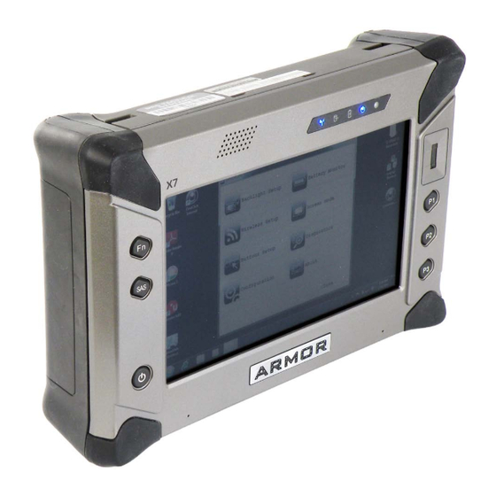
WLAN / WWAN / GPS INDICATOR FINGERPRINT SPEAKER BRIGHTNESS SENSOR ANTENNAS PANEL DUAL MODE DISPLAY LEFT RIGHT CONTROL CONTROL PANEL PANEL NOISE CANCELLING MICROPHONES Figure 1. ARMOR X7 Key Features – Front View 9711-26400-0001 EXPORT CONTROLLED – SEE PAGE 3 Rev A... -
Page 31: Display
SECTION 2 LEARNING ABOUT YOUR ARMOR X7 PAGE 31 Dis pla y The X7 display is a high-brightness, high-contrast LCD display with anti-glare filtering that ensures your screen can be clearly viewed even in bright sunlight. A replaceable screen protector is attached at the factory to reduce glare and protect the touch screen surface. - Page 32 SECTION 2 LEARNING ABOUT YOUR ARMOR X7 PAGE 32 P r o gr a mma ble B utto ns (P B s ) P 1, P 2, P 3 The PBs can be programmed to activate different functions such as controlling brightness, changing volume level or activating an application with just a single press.
-
Page 33: Table 1. Initial Power Button Actions
SECTION 2 LEARNING ABOUT YOUR ARMOR X7 PAGE 33 Table 1. Initial Power Button Actions Operating State Power Button Action Result Computer powered off Press and hold for at least Computer turns on and boots up 1 second and then release into new Windows session. -
Page 34: Indicator Panel
Charging/Fault indicator to flash 4-5 times, indicating that you need to connect external power and recharge the batteries. P ow er O n Indic a to r A blue LED that is on steady whenever power is applied to the ARMOR X7 and is off when power is shut down. 9711-26400-0001 EXPORT CONTROLLED –... -
Page 35: Speaker
SECTION 2 LEARNING ABOUT YOUR ARMOR X7 PAGE 35 A m bient L ight S ens o r ( A L S ) When the X7 display is in automatic brightness mode, the ALS senses changes in surrounding light levels and adjusts the display brightness and indicator light levels accordingly. If the surrounding light level increases, the display and indicator brightness will increase proportionally;... -
Page 36: Rear Panel Features
SECTION 2 LEARNING ABOUT YOUR ARMOR X7 PAGE 36 R ea r P a nel F ea tures The rear panel of the X7 houses a built-in webcam, a cooling register, two battery bays and a removable cooling register/cover that provides access to installed radio modules, a SIM card socket, and a micro SD socket. -
Page 37: Cooling Register
SECTION 2 LEARNING ABOUT YOUR ARMOR X7 PAGE 37 C o o ling R egis ter ARMOR computers are designed to operate in wet and dirty environments under extreme temperatures. Because the tablet is sealed against contamination, it incorporates passive cooling which channels the internal heat to the cooling register at the back of the unit. -
Page 38: Bottom Panel Features
SECTION 2 LEARNING ABOUT YOUR ARMOR X7 PAGE 38 WEBCAM LENS Figure 6. X7 Webcam B ottom P a nel F ea tures The bottom panel houses a DC power input jack, a mini-USB connector and a 20-pin docking connector. The docking connector contains two RF ports to connect the X7 to external GPS and wireless antennas. -
Page 39: Included Components, Accessories And Support
SECTION 2 LEARNING ABOUT YOUR ARMOR X7 PAGE 39 Inc luded C o mponents , A c c es s ories a nd S upport B a tter ies Your X7 batteries are high efficiency lithium-ion batteries that are “hot swappable.” That is, if you have two batteries installed, you can replace one battery while the computer operates on the other battery. -
Page 40: Active Pen With Tether
Figure 9. The ARMOR X7 Pen A C A da pter a nd P ow er C o rd Included with your ARMOR X7 is a +19 VDC ± 5%, 2 amp AC power adapter, or “AC Adapter” 0000F50874-0000) (P/N . -
Page 41: Armor Cloth
SECTION 2 LEARNING ABOUT YOUR ARMOR X7 PAGE 41 Figure 10. X7 AC Adapter A R MO R C lo th This microfiber cloth is specially designed to clean the display screen of dust and fingerprints. Caring For the Display Screen for important information about using this cloth with the X7 display. -
Page 42: Subscriber Identity Module (Sim) Card Support
S ec u r e Digita l (S D) C a r d R ea der S u ppo rt The ARMOR X7 also provides a card reader for a micro SD or SDHC card in capacities of 8, 16, or 32 GB. -
Page 43: Trusted Platform Module (Tpm) Support
Trusted Computing Group (TCG) Trusted Platform Module Specification 1.2. The TPM module is connected to the low pin count (LPC) bus. For more information on TPM capabilities with the ARMOR X7, contact DRS Tactical Systems, Inc. toll free at 1-800-872-1100. -
Page 44: Figure 15. X7 Internal Flexspace
EXPANSION CUSTOM I/O CONNECTOR CONNECTOR MODULE Figure 16. ARMOR X7 Battery Adapter Flexspace Concept For more information on the X7’s expansion capabilities, contact DRS Tactical Systems, Inc. toll free at 1-800-872-1100. 9711-26400-0001 EXPORT CONTROLLED – SEE PAGE 3 Rev A... -
Page 45: Optional Add-Ons And Accessories For Your X7
C o mpa c t K ey bo a r d 0000-16200-0000) A reduced-size USB keyboard (P/N is available for use with the ARMOR X7 computer. The keyboard is approximately half the size of a standard keyboard and can be connected directly to the X7 using a mini-USB adapter (nor supplied) or to a desk docking station to conserve space on a table or desktop. -
Page 46: Mini-Usb Adapter
SECTION 2 LEARNING ABOUT YOUR ARMOR X7 PAGE 46 Mini-U S B A d a pter This USB to mini-USB adapter (P/N 0000F50015-0000) is available to adapt the X7 mini-USB port to a standard USB cable or flash drive connector. -
Page 47: Docking Stations
SECTION 2 LEARNING ABOUT YOUR ARMOR X7 PAGE 47 Do c k ing S ta tio ns There are a number of new docking stations available to support and enhance the X7, either for the desktop or for use in a vehicle. -
Page 48: Figure 18. X7 Rf Vehicle Dock
SECTION 2 LEARNING ABOUT YOUR ARMOR X7 PAGE 48 V ehic le Do c k The X7 vehicle dock (P/N 9800F26300-0000) is made of UV-resistant high-impact plastic that weighs less than 2 lbs. It is designed to be attached to any mount that accepts the Video Electronics Standards Association (VESA) 75 mm hole pattern. -
Page 49: Figure 19. Examples Of X7 Vehicle Dock Mounting Solutions
SECTION 2 LEARNING ABOUT YOUR ARMOR X7 PAGE 49 V ehic le Do c k Mo un ting S o lu tio ns The X7 vehicle dock is rugged and light weight and can be adapted to just about any mounting situation from console and dashboard installation to bulkhead and cab roof installation. -
Page 50: Figure 21. Industrial Vehicle Surge Suppressor
PAGE 50 S ur ge S uppr es s o r Surge protection is required for all vehicle installations of the ARMOR X7. This surge protection is necessary to prevent damage to sensitive electrical circuits in the X7 tablet. If the vehicle system voltage remains within the limits of 11-14 VDC, a regulated power supply is... -
Page 51: Figure 23. Sample X7 Vehicle Dock Installation Package
SECTION 2 LEARNING ABOUT YOUR ARMOR X7 PAGE 51 C o mplete X 7 V ehic le Do c k Ins ta lla tio n A complete vehicle dock installation includes a docking station, breakout box, 50-pin cable, surge suppressor or power supply and mount of your choice. A sample system is shown in Figure 23 (external antennas and cables not shown). -
Page 52: X7 Specifications
SECTION 2 LEARNING ABOUT YOUR ARMOR X7 PAGE 52 X 7 S pec ific a tions NOTE: These specifications are subject to change. Please contact DRS Tactical Systems toll free at 1-888-872-1100 for updates of a particular specification. Operating System Microsoft Windows7 Professional®... - Page 53 SECTION 2 LEARNING ABOUT YOUR ARMOR X7 PAGE 53 • 3x USB 2.0 • 2x 5V Ground/Open Input Devices (GPIO) • Dock detect/dock enabled discrete • GPS antenna, coaxial • WWAN antenna, coaxial Mechanical features support one-handed docking Wireless Standard: •...
- Page 54 SECTION 2 LEARNING ABOUT YOUR ARMOR X7 PAGE 54 TPM security chip v.1.2 Fingerprint sensor ISO 7816 Smart Card (FIPS 201) compliant Durability Features MIL-STD-810G certified (6' drop) IP67 certified including battery pack Injection molded plastic housing with internal magnesium frame and rubber over mold...
-
Page 55: Figure 24. X7 Internal Block Diagram
SECTION 2 LEARNING ABOUT YOUR ARMOR X7 PAGE 55 DDR2 1GB/2GB LVDS LCD Display Backlight Driver Touch Panel Pineview-M Flexspace Exp Optically Bonded LCD Controller Assy X4 DMI USB 0 PCIe X1 USB Connector Half-Size Mini-PCIe WLAN USB 1 DOCK Conn... - Page 56 SECTION 2 LEARNING ABOUT YOUR ARMOR X7 PAGE 56 This Page Intentionally Left Blank 9711-26400-0001 EXPORT CONTROLLED – SEE PAGE 3 Rev A...
-
Page 57: 3. G E T T In G S T A R T E D
3. G E T T IN G S T A R T E D The information in this section will help you get started using your ARMOR X7 computer. Please read all warnings, cautions and notes prior to each procedure or step. -
Page 58: Installing And Charging The Batteries
SECTION 3 GETTING STARTED PAGE 58 Ins ta lling a nd C ha rging the B a tteries The first step to getting your X7 operating is to install and charge the batteries. The batteries are inserted into slots or “bays” on each side of the computer as shown in Figure 25. The batteries are identical and can be installed in either bay. -
Page 59: Table 2. Installing The X7 Batteries
SECTION 3 GETTING STARTED PAGE 59 Table 2. Installing the X7 Batteries STEP ACTION Place the flat surface of the first battery on the left side compartment tray with the locking slots facing toward the computer. Push and hold the battery latch and slide the battery toward the computer until the locking bar engages and the battery is flush against the compartment wall. -
Page 60: Figure 26. X7 Battery
SECTION 3 GETTING STARTED PAGE 60 FUEL GAUGE FUEL GAUGE BATTERY BUTTON CONNECTOR 1 2 3 4 5 Figure 26. X7 Battery 9711-26400-0001 EXPORT CONTROLLED – SEE PAGE 3 Rev A... -
Page 61: Turning On Your X7 For The First Time
SECTION 3 GETTING STARTED PAGE 61 T urning O n y o ur X 7 for the F irs t T ime Follow the procedure in Table 3 to configure your Windows 7 operating system. NOTE The first user account you create will be an Administrator account. You will need to use this account for any changes that require administrator privileges. -
Page 62: Turning The Computer On Normally
T urning the C omputer O n N orma lly Turn the computer on by pressing the Power button for at least 1 sec and then releasing it. The ARMOR X7 will perform self-checking routines during the start-up process. All units are configured at the factory to automatically boot to the Microsoft Windows desktop unless a custom configuration has been requested. -
Page 63: Emergency Shutdown
SECTION 3 GETTING STARTED PAGE 63 You can re-program the power button to shut down the computer when pressed while the computer is running. Refer to Changing the Power Button Default Action for instructions. E mergenc y S hutdow n If an emergency condition occurs where the computer needs to be shut down immediately, press and hold the Power button for more than five seconds. -
Page 64: Indicator State Summary
SECTION 3 GETTING STARTED PAGE 64 Indic a tor S ta te S umma r y Table 4 lists all states for the various X7 indicator LEDs (refer to Indicator Panel for a description of each indicator). Table 4. X7 Indicator State Summary THIS MEANS: IF THE INDICATION... - Page 65 SECTION 3 GETTING STARTED PAGE 65 IF THE THIS MEANS: INDICATION EXTERNAL BATTERY POWER POWER IS: MODE Flashing Power on Connected Installed Battery charging has amber at 1/2 or off been suspended due to sec rate extreme battery temperature. Charging will resume when...
-
Page 66: Configuring And Controlling Your Wireless Radios
SECTION 3 GETTING STARTED PAGE 66 C onfiguring a nd C ontro lling y o ur W ireles s R a dios For instructions on configuring and controlling your wireless radios, including the optional WWAN radio and optional GPS receiver, refer to Section 4, Networking. You will also find instructions for connecting to a cabled LAN. -
Page 67: Configuring Your Audio System
SECTION 3 GETTING STARTED PAGE 67 C onfiguring y our A udio S y s tem Follow the procedure in Table 6 to configure your speaker. Follow the procedure in Table 7 to configure your microphones. Table 6. Configuring the Speaker STEP ACTION CONDITION OR INDICATION... -
Page 68: Figure 28. Microphone Main Tab
SECTION 3 GETTING STARTED PAGE 68 Table 7. Configuring your Microphones STEP ACTION CONDITION OR INDICATION Click on the Microphone main tab at The Microphone main tab opens with the Microphone Effects sub-tab displayed, the top of the page. as shown in Figure 28. Set up and adjust your microphones. -
Page 69: Operating The X7 Display
SECTION 3 GETTING STARTED PAGE 69 O pera ting the X 7 Dis pla y S elec ting th e Dis pla y Mo de Your X7 has the capability to operate with both a touch screen and a pen screen enabled (dual mode) or you can select touch screen only or pen screen only. -
Page 70: Adjusting Screen Brightness
The brightness of the LCD display is controlled by adjusting the backlight intensity either automatically or manually. When you first receive your ARMOR X7, the brightness mode is set to Automatic. To switch to Manual brightness control, or switch back to Automatic mode, open ARMORutils and click on the Backlight Setup option in the ARMORutils Main dialog window. - Page 71 SECTION 3 GETTING STARTED PAGE 71 NOTE You must keep the ALS uncovered to allow proper automatic brightness adjustment. S elec ting a n A u to m a tic Mo de P r o file You can tailor the automatic brightness adjustment by selecting one of the 5 pre-configured brightness profiles.
-
Page 72: Working With The Pen Screen
SECTION 3 GETTING STARTED PAGE 72 W o r k ing w ith the P en S c r een When the pen screen is active, you can steer the pointer and perform many functions by simply hovering close to the screen without actually touching it. Other functions are initiated by pressing the tip to the screen surface to activate the tip switch. - Page 73 SECTION 3 GETTING STARTED PAGE 73 P en S c r een A djus tments You can change attributes related to use of the pen with the pen screen by selecting Start à Control Panel à Hardware and Sound à and clicking on one or more of the following utilities: •...
-
Page 74: Working With The Touch Screen
SECTION 3 GETTING STARTED PAGE 74 W o r k ing w ith the T o u c h S c r een When the touch screen is active, the pressure of a fingertip or passive stylus (not supplied) against the screen is used to duplicate the actions of a two-button mouse. NOTE Tapping with a stylus tip requires only light to moderate pressure. - Page 75 SECTION 3 GETTING STARTED PAGE 75 T o uc h S c r een C a libr a tio n NOTE If your X7 is in Dual Mode display, you cannot use the active pen that came with your X7 to calibrate the touch screen since the digitizer will detect the active pen tip and not allow you to proceed.
-
Page 76: Entering Data Using The Input Panel
SECTION 3 GETTING STARTED PAGE 76 E nter ing D a ta U s ing the Inpu t P a nel The input panel is a virtual keyboard and handwriting entry tool that is located on your desktop. It is hidden just off the top left or right side of the display. The edge appears in the upper left corner when you tap anywhere on the screen with a fingertip, stylus or the active pen, as shown in Figure 31. - Page 77 SECTION 3 GETTING STARTED PAGE 77 E diting D o c uments When you tap on an open text document such as a Word document, a keyboard icon will appear on the screen. Tap on this icon to open the input panel. C o nfigur ing Inpu t P a nel O ptio ns The Input Panel Options window is where you can change a wide variety of Input panel display and operating features.
-
Page 78: Using The Fingerprint Sensor (Fps)
SECTION 3 GETTING STARTED PAGE 78 U s ing the F ingerpr int S ens or (F P S ) A c tiv a ting th e F P S S o ftwa r e To initially set up your FPS software, double-click on the TrueSuite icon on the desktop and click on Get Started to begin. -
Page 79: Truesuite Options And Settings
SECTION 3 GETTING STARTED PAGE 79 T r u eS u ite O ptio ns a nd S ettings A complete description of the options and settings of the TrueSuite software is beyond the scope of this user’s guide. Click on the “?” in the upper right corner of the window to access the application’s help resources for detailed descriptions and instructions. -
Page 80: Using The Webcam
SECTION 3 GETTING STARTED PAGE 80 U s ing the W ebc a m C a ptu r ing Ima ges a nd V ideo Image and video capture is performed using the built-in webcam and image capture software. Your X7 is provided with a complementary version of Picasa 3™ to demonstrate the image capture process, or you may wish to download and install your own camera application. -
Page 81: Scanning A Barcode
SECTION 3 GETTING STARTED PAGE 81 CAPTURE BUTTON Figure 34. Picasa Application Window S c a nning a B a r c o de The built-in webcam and the application software of your choice will allow you to scan various types of barcodes and incorporate them in to your documents. -
Page 82: Figure 36. Webcam Barcode Scanner® Application Window
SECTION 3 GETTING STARTED PAGE 82 Table 11. Scan UPC-10, EAN-13 and ISBN Barcodes STEP ACTION COMMENTS Double-click on the Webcam Barcode The application window opens as shown Scanner icon on the desktop. in Figure 36 Hold the barcode to be scanned 2-3” from A tone will announce successful barcode the camera and hold it steady. -
Page 83: Figure 38. Quickmark® Barcode Scanner Application Window
SECTION 3 GETTING STARTED PAGE 83 Table 12. Scan a 2D Barcode STEP ACTION COMMENTS Double-click on the QuickMark icon on QuickMark® application window the desktop. opens as shown in Figure 38 Hold the barcode to be scanned 2-3” from An audible signal will sound upon capture the camera, and the barcode information will be... -
Page 84: Using The Screen Magnifier
SECTION 3 GETTING STARTED PAGE 84 U s ing the S c reen Ma gnifier Some text and images on a small screen can be difficult to see clearly. Your X7 has a handy application that will magnify a portion of the screen and help you see more effectively. The program is called Virtual Magnifying Glass™. -
Page 85: Tips For Proper Use And Care Of Your X7
T ips for P ro per U s e a nd C a re O f Y o ur X 7 There are certain precautions you should take to ensure that your ARMOR X7 computer continues to provide you with reliable service: •... - Page 86 SECTION 3 GETTING STARTED PAGE 86 This Page Intentionally Left Blank 9711-26400-0001 EXPORT CONTROLLED – SEE PAGE 3 Rev A...
-
Page 87: 4. N E T W O R K In G
Table of Contents List of Figures List of Tables Acronyms Glossary 4. N E T W O R K IN G Your ARMOR X7 comes configured with two wireless network capabilities: Wi-Fi™ (wireless fidelity) and Bluetooth®. The Wi-Fi network is primarily used for higher bandwidth connections such as Internet or a company LAN. -
Page 88: Figure 41. Network And Sharing Center Window
SECTION 4 NETWORKING PAGE 88 STEP ACTION COMMENTS Click on the “Connect to a network” The label “Connected” will appear beside link to open the window shown in each network currently Figure 42. Click outside this window to connected other available close it. -
Page 89: Managing Your Bluetooth Connections
SECTION 4 NETWORKING PAGE 89 Figure 42. Currently Connected and Available Wi-Fi Networks Ma na ging y our B luetoo th C onnec tions Your X7 comes equipped with Bluetooth® networking. However, to utilize this feature, you must “associate” your computer with any Bluetooth devices you want to connect. To see what Bluetooth devices are available and to add or remove devices, follow the procedure in Table 14. -
Page 90: Figure 43. Devices And Printers Window
SECTION 4 NETWORKING PAGE 90 STEP ACTION COMMENTS To remove a device, click on the “Remove a device” option in the toolbar. For additional information about these windows, click on the Help icon. Figure 43. Devices and Printers Window 9711-26400-0001 EXPORT CONTROLLED –... -
Page 91: Figure 44. Bluetooth Settings Window
SECTION 4 NETWORKING PAGE 91 Figure 44. Bluetooth Settings Window 9711-26400-0001 EXPORT CONTROLLED – SEE PAGE 3 Rev A... -
Page 92: Managing Your Ethernet Connection
SECTION 4 NETWORKING PAGE 92 Ma na ging y our E thernet C onnec tion Your X7 supports a cabled 10/100 Ethernet connection through a desk dock or a vehicle dock using a USB to LAN converter chip located in the docking station breakout box. An RJ45 Ethernet connector is provided at the breakout box for physical connection to the Ethernet LAN. -
Page 93: Figure 45. Internet Service Provider Information Window
SECTION 4 NETWORKING PAGE 93 Enter your user name and password in fields provided. Click Remember this Password option if you don’t want to have to enter the password each time you access the network. Enter the IP address provided by your IT If the address is already showing, you do department or internet service provider not have to enter it again. -
Page 94: Activating The Optional Gobi® Wwan Radio
OneClick Internet application and before you log in. However, when you first receive your ARMOR X7, NDIS is not automatically available and must be manually configured in order to use it. -
Page 95: Important Notes About Using Ndis
SECTION 4 NETWORKING PAGE 95 CAUTION! Before uninstalling the OneClickInternet application with NDIS enabled, make sure that the “Gobi NDIS Auto Connect” option is unchecked in the Settings/General tab. Otherwise module will always connect automatically on the next start up. Without the OneClickInternet application installed, you cannot disable this feature. -
Page 96: Activating The Optional Gps Receiver
SECTION 4 NETWORKING PAGE 96 • If you reboot the computer, NDIS will maintain your connection during the reboot. • Selecting the “Auto Launch” option on the Settings page when NDIS is selected is not recommended as this will launch the OneClickInternet application upon reboot which will restart your connection. -
Page 97: The U-Center Gps Application Window
SECTION 4 NETWORKING PAGE 97 T he u -c enter G P S A pplic a tio n W indow The diagram in the center shows the approximate positions of satellites relative to your location that are within range of the receiver. The graph at the bottom of the page shows the signal strength of each satellite. -
Page 98: Table 18. Obtaining The Agps Password From U-Blox
A c tiva ting A s s is ted G P S AGPS is free with your purchase of your ARMOR X7 but you must obtain the necessary AGPS password from u-blox by following the procedure in Table 18. -
Page 99: Enabling And Disabling Your Wireless Radios
SECTION 4 NETWORKING PAGE 99 ENTER YOUR ENTER YOUR EMAIL ADDRESS AGPS PASSWORD HERE HERE Figure 48. u-center AssistNow Online Window E na bling a nd Dis a bling Y our W ireles s R a dios You may wish to turn off one or more of your radios to save power, to avoid interfering with other radio systems, or just to ensure your privacy. -
Page 100: Table 19. Enabling And Disabling Your Wireless Radios
SECTION 4 NETWORKING PAGE 100 Table 19. Enabling and Disabling Your Wireless Radios Step Action Comment Click on the ARMORutils icon on the This will open the Wireless Setup dialog desktop and select the Wireless Setup window, as shown in Figure 53. option. -
Page 101: Wireless Signal Quality
SECTION 4 NETWORKING PAGE 101 W ireles s S igna l Q ua lity Wireless signal quality is affected by several conditions: • Distance from a Wi-Fi access point. • Access rights (set up through an administrator). • Your security settings. •... -
Page 102: Figure 49. Armorutils Wireless Setup Dialog
SECTION 4 NETWORKING PAGE 102 Table 20. Configuring the X7 to use External Antennas STEP ACTION CONDITION OR INDICATION Place the X7 in the docking cradle (see Figure 18) and press down on the top clamp until it locks. Double-click on the ARMORutils icon The ARMORutils Main Window opens. -
Page 103: 5. Y O U R A R Mo R X 7 S O F T W A R E
SECTION 5 YOUR ARMOR X7 SOFTWARE PAGE 103 Table of Contents List of Figures List of Tables Acronyms Glossary 5. Y O U R A R MO R X 7 S O F T W A R E Your ARMOR X10gx comes with a variety of software applications. Many of these are standard... -
Page 104: Armorutils™ Application
SECTION 5 YOUR ARMOR X7 SOFTWARE PAGE 104 A R MO R utils ™ A pplic a tion The ARMORutils application is provided to help you configure and manage your X7 computer. It contains settings and information about screen setup, wireless configuration, battery status and much more. -
Page 105: Exiting From Armorutils
SECTION 5 YOUR ARMOR X7 SOFTWARE PAGE 105 E x iting fr o m A R MO R u tils When you click on the CLOSE button on the ARMORutils main window or click on the red “X” at the upper right corner, you are only closing the main window – you are not exiting from the utility. -
Page 106: Backlight Setup Dialog Window
SECTION 5 YOUR ARMOR X7 SOFTWARE PAGE 106 B a c k light S etu p Dia lo g W indow The Backlight Setup dialog window allows you to adjust the screen brightness manually or automatically and to select from a series of preset profiles to automatically restrict the brightness range under specific lighting conditions. - Page 107 SECTION 5 YOUR ARMOR X7 SOFTWARE PAGE 107 A u to ma tic B r igh tne s s Mo de P r o files Everyone’s eyes react differently to changes in light levels and there may be times when a particular range of automatic brightness adjustment is uncomfortable for you.
-
Page 108: Wireless Setup Dialog Window
W ir eles s S etu p Dia lo g W indow The Wireless Setup dialog allows you to enable or disable each wireless radio installed in your ARMOR X7. It also provides controls for external antennas connected through an X7 vehicle dock. - Page 109 There is an ON and an Off button for each radio that is installed or supported. When you first start your ARMOR X7, all installed radios are ON or enabled (default condition). Each radio can then be disabled by pressing its OFF button and re-enabled by pressing its ON button. Refer to Enabling and Disabling Your Wireless Radios for information on how to use these buttons.
-
Page 110: Buttons Setup Dialog Window
SECTION 5 YOUR ARMOR X7 SOFTWARE PAGE 110 B u tto ns S etu p Dia lo g W indow The Buttons Setup dialog window is shown in Figure 54. It allows you to assign two different functions for each programmable button (or “PB”) labeled P1, P2 and P3. These buttons are located on the right control panel (see Figure 2). -
Page 111: Figure 55. Armorutils Programmable Button Options Menu
SECTION 5 YOUR ARMOR X7 SOFTWARE PAGE 111 S elec ting a F unc tio n Click on the menu arrow next to the PB or PB combo and select the desired function, then click on the OK button to save your setting. Figure 55 shows a menu opened for the P3 button. - Page 112 SECTION 5 YOUR ARMOR X7 SOFTWARE PAGE 112 • Volume Decrease – Decreases sound volume in steps. • Volume Mute – Toggles volume ON or OFF. • Rotate Screen 90 degrees – Rotates the screen 90 degrees clockwise with each press.
-
Page 113: Configuration Dialog Window
SECTION 5 YOUR ARMOR X7 SOFTWARE PAGE 113 C o nfigu r a tio n Dia lo g W indow The Configuration Dialog window provides visual confirmation of those wireless radios that are installed in your X7. If a radio is installed and available, the associated icon and status will appear in dark contrast. -
Page 114: Figure 57. User Access Settings Dialog
SECTION 5 YOUR ARMOR X7 SOFTWARE PAGE 114 A dminis tr a tio n B utto n The Administration button is normally hidden from view. To make this button available, press and hold the Fn button on the right control panel and click on the Configuration option on the ARMORutils Main window. -
Page 115: Figure 58. Example Of The Armorutils Main Screen With Options Disabled
SECTION 5 YOUR ARMOR X7 SOFTWARE PAGE 115 Figure 58. Example of the ARMORutils Main Screen with Options Disabled 9711-26400-0001 EXPORT CONTROLLED – SEE PAGE 3 Rev A... -
Page 116: Battery Monitor Dialog
SECTION 5 YOUR ARMOR X7 SOFTWARE PAGE 116 B a tter y Mo nito r Dia lo g The Battery Monitor dialog window is shown in Figure 59. This window provides the following information about each battery: • Current charge level (% of the maximum energy capacity) •... -
Page 117: Figure 60. Armorutils Battery Information Window
SECTION 5 YOUR ARMOR X7 SOFTWARE PAGE 117 B a tter y 1 a nd B a tte r y 2 Deta ils B u tto ns Select a Battery Details button to open a Battery Information window. Figure 60 shows a typical window for the #1 battery. -
Page 118: Figure 61. Armorutils Charger Control Settings Window
SECTION 5 YOUR ARMOR X7 SOFTWARE PAGE 118 Remaining Capacity – This is the current energy level expressed in mAh instead of % of charge. Maximum Capacity – This is the current maximum energy capacity that the battery can achieve. This value is determined primarily by the battery’s age, operating temperature history and total number of accumulated charge cycles. - Page 119 SECTION 5 YOUR ARMOR X7 SOFTWARE PAGE 119 C ha r ge B o th If you select Charge Both, both batteries will charge at the same time regardless of individual battery charge level. The total charge level indicated is determined by adding the charge of both batteries and dividing this sum by 2.
-
Page 120: Figure 62. Battery Conditioning Window
SECTION 5 YOUR ARMOR X7 SOFTWARE PAGE 120 Figure 62. Battery Conditioning Window S ta r t C y c le B utto n Click on the START CYCLE button to begin the conditioning process. T er mina te C yc le B u tto n Click on the TERMINATE CYCLE button at any time to stop the conditioning process. -
Page 121: Screen Setup Dialog Window
SECTION 5 YOUR ARMOR X7 SOFTWARE PAGE 121 S c reen S etu p Dia lo g W indow The Screen Setup dialog (Figure 63) is used to select the current display mode and to access calibration routines for both the touch and pen screens. There are three display modes: Dual, Touch Only and Pen Only. -
Page 122: Figure 64. Screen Setup Dialog With Touch Screen Only Enabled
SECTION 5 YOUR ARMOR X7 SOFTWARE PAGE 122 Figure 64. Screen Setup Dialog with Touch Screen Only Enabled NOTE You can also find options to change the display mode through pen and touch utilities in Windows Control Panel. However, you should... -
Page 123: Diagnostics Dialog Window
SECTION 5 YOUR ARMOR X7 SOFTWARE PAGE 123 Dia gno s tic s Dia lo g W indow The Diagnostics window displays the following internal temperatures of the X7 tablet, as shown in the example in Figure 65: • CPU core temperature (DTS and Diode) •... -
Page 124: Figure 66. Armorutils Event Recorder Window
SECTION 5 YOUR ARMOR X7 SOFTWARE PAGE 124 TIME REMAINING APPEARS HERE Figure 66. ARMORUtils Event Recorder Window L o g F ilena me The filename that appears in the Log Filename field when you first open the Event Recorder window is the default log file in the ARMORutils application folder. - Page 125 SECTION 5 YOUR ARMOR X7 SOFTWARE PAGE 125 Your Event Recorder is pre-configured from the factory with this option checked. Uncheck it if you want to record data continuously. S ta tus The Status panel displays the time the logging was started, the time remaining (if Auto Logging is used) and the time logging was stopped (either at the end of an auto-timed period or when the STOP LOGGING button was selected).
-
Page 126: Figure 67. Sample Event Log File
SECTION 5 YOUR ARMOR X7 SOFTWARE PAGE 126 DEFINITIONS Figure 67. Sample Event Log File 9711-26400-0001 EXPORT CONTROLLED – SEE PAGE 3 Rev A... -
Page 127: Armorutils About Window
SECTION 5 YOUR ARMOR X7 SOFTWARE PAGE 127 A R MO R u tils A bo u t W indo w The About window (Figure 68) displays the current version and release date of the ARMORutils software. It also provides a contact telephone number for the DRS Tactical Systems Technical Support call center and the internet address to the ARMOR website where you can log on to access support information. -
Page 128: Getting Started With Windows 7
SECTION 5 YOUR ARMOR X7 SOFTWARE PAGE 128 G etting S ta rted w ith W indow s 7 Click on Start à Getting Started to open the Windows welcome page (Figure 69) and access a number of helpful links and resources. NOTE: Screen content and layout may vary depending on your version of Windows 7 and any added service packs or updates. -
Page 129: Figure 70. Pen And Touch Utility - Pen Options Tab
SECTION 5 YOUR ARMOR X7 SOFTWARE PAGE 129 P en a nd T o u c h U tility The Pen and Touch utility is a Windows program that provides settings that effect how the active pen works with the pen screen and how a fingertip or passive stylus works with the touch screen. -
Page 130: Figure 71. Pen And Touch Utility - Flicks Tab
SECTION 5 YOUR ARMOR X7 SOFTWARE PAGE 130 P en B utto ns P a nel Use the Pen button as a right-click equivalent option – This option is overridden by the pen button options in the Pen tab of the Pen Tablet Properties utility, regardless of whether it is checked or not.
Need help?
Do you have a question about the ARMOR X7 and is the answer not in the manual?
Questions and answers