Table of Contents
Advertisement
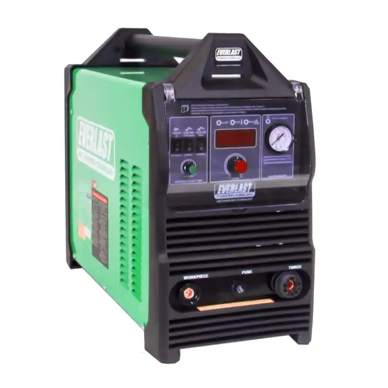
EVERLAST
POWERPLASMA S SERIES
60-100 Amp S Series IGBT Inverter Platform Plasma Cutters
CC
PAC
IGBT
1
~
PHASE
Operator's Manual for the PowerPlasma S Series
(60-100 Amp Models)
Safety, Setup and General Use Guide
Rev. 5
0 000330-18
everlastwelders.com
Specifications and Accessories subject to change without notice.
1-877-755-9353
329 Littlefield Ave. South San Francisco, CA 94080 USA
Advertisement
Table of Contents

Related Manuals for Everlast PowerPlasma 60S


Summary of Contents for Everlast PowerPlasma 60S
- Page 1 EVERLAST POWERPLASMA S SERIES 60-100 Amp S Series IGBT Inverter Platform Plasma Cutters IGBT PHASE Operator’s Manual for the PowerPlasma S Series (60-100 Amp Models) Safety, Setup and General Use Guide Rev. 5 0 000330-18 everlastwelders.com Specifications and Accessories subject to change without notice.
-
Page 2: Table Of Contents
Everlast Power Equipment INC. does not guarantee the accuracy, completeness, authority or authenticity of the information contained within this manual. -
Page 3: Letter To The Customer
Dear Customer, THANKS! You had a choice, and you bought an Everlast. We appreciate you as a customer and hope that you will enjoy years of use from your welder. Please go directly to the Everlast website to register your unit and receive your warranty information. -
Page 4: Everlast Contact Information
Serial number: ____________________________ Model number: ____________________________ Date of Purchase:__________________________ Contact Information Everlast US: Everlast consumer satisfaction email: sales@everlastwelders.com Everlast Website: everlastwelders.com Everlast Technical Support: support@everlastwelders.com Everlast Support Forum: http://www.everlastgenerators.com/forums/index.php Main toll free number: 1-877-755 WELD (9353) 9am—5pm PST M-F 11am-4pm PST Sat. -
Page 5: Safety Precautions
Safety Precautions Everlast is dedicated to providing you with the best possible equipment and service to meet the demanding jobs that you have. We want to go beyond merely delivering a satisfactory product to you. That is the reason we offer free technical support to assist you with your needs should an occasion occur. - Page 6 SAFETY PRECAUTIONS These safety precautions are for protection of safety and health. Failure to follow these guidelines may result in serious injury or death. Be careful to read and follow all cautions and warnings. Protect yourself and others. Welding and cutting processes produce high levels of ultraviolet (UV) radiation that can cause se- vere skin burn and damage.
- Page 7 SAFETY PRECAUTIONS WARNING! Persons with pacemakers should not weld, cut or be in the welding area until they consult with their physician. Some pacemakers are sensitive to EMF radiation and could severely malfunction while welding or while being in the vicinity of someone welding. Serious injury or death may occur! Welding and plasma cutting processes generate electro-magnetic fields and radiation.
- Page 8 SAFETY PRECAUTIONS continued WARNING! Electrical shock can kill. Make sure all electrical equipment is properly grounded. Do not use frayed, cut or otherwise damaged cables and leads. Do not stand, lean or rest on ground clamp. Do not stand in water or damp areas while welding or cutting. Keep work surface dry. Do not use welder or plasma cutter in the rain or in extremely humid conditions.
-
Page 9: Introduction And Specifications
Section 1 Introduction and Specifications PowerPlasma 60S/80S/100S Regulator Assembly with Bracket Consumable Starter Kit (Qty. and items may vary) Work Clamp iPT 60/80/100 Torch NOTE: Accessory and consumable style and quantities are subject to change without notice. -
Page 10: Unit Specifications
Plan the unit’s daily use around the recommended average cut thickness for best results and speed. This is an industry standard recommendation and is not unique to Everlast PowerPlasma models. CNC cut thickness is further reduced as it is typically a 100% duty cycle operation which will require a lower maximum amp setting. -
Page 11: General Overview
Manual post-flow control is a unique feature with the welder will automatically stop welding when an over- Everlast and provides better post flow control of the heat condition has occurred. Heat will continue to be air so consumable life is increased and the torch can generated by and transferred to the electronics after be cooled for an extended period of time if desired. -
Page 12: Quick Setup Guide, Torch Connection
Section 2 QUICK SETUP AND USE GUIDE QUICK SETUP GUIDE: CONNECTIONS WORK (+) TORCH (-) CENTRAL CONNECTOR... -
Page 13: Rear Panel Gas Connection And Wiring
Section 2 QUICK SETUP AND USE GUIDE QUICK SETUP GUIDE: REAR CONNECTIONS AND WIRING (US/Canada) IMPORTANT: TO PREVENT AIR LEAKS, MAKE SURE TUBING ENDS ARE SQUARELY CUT AND FULLY INSERTED. TO RELEASE TUBING: PRESS GENTLY ON PLASTIC COLLAR SO THAT IT COMPRESSES INTO HOUSING AND THEN PULL TUBING OUT. 1~220 VAC PUSH TO CONNECT TUBING NOTE: WHEN ASSEMBLING AIR REGULATOR NOTICE THE MARKINGS THAT ARE STAMPED... -
Page 14: Compressor And Air Dryer Diagram
Section 2 QUICK SETUP AND USE GUIDE QUICK SETUP GUIDE: REAR CONNECTIONS AND WIRING Compressor and Dryer Diagram Compressor and Air hose with- fittings (Customer Supplied) Regulator Assembly with built-in water trap and dirt filter (Included) 1/4” Automotive Universal style quick connector (Included) 1~220 VAC Air Dryer/Oil Filter... -
Page 15: Front Panel Features And Controls
Section 2 QUICK SETUP AND USE GUIDE FRONT PANEL FEATURES AND CONTROLS 1. AMP DISPLAY 12. ON/TEMP/O.C 2. AIR PRESSURE OK TO CUT 11. AIR FLOW FUNCTION 10. PILOT ARC OPERATION 3. AIR PRESSURE GAUGE 9. 2T/4T LOCK 8. AIR POST FLOW 4. - Page 16 Cycle the machine on and off. If the light clears and cutting resumes, the fault has been cleared. If the unit will not work and/or the light remains on, contact Everlast Tech Support.
-
Page 17: Rear Panel Features And Controls
Section 2 QUICK SETUP AND USE GUIDE REAR PANEL FEATURES AND CONTROLS 1. CNC CONNECTION 2. 2-POLE POWER SWITCH 6. REGULATOR ASSY. 1~220 VAC 3. POWER CABLE 1 ~ 220/240V 1~220 V INLET 5. HF GROUND BOLT 4. GAS INLET... - Page 18 Less than 5% THD is preferred. Operating the unit on square wave output or modified sine wave generators is strictly prohibited. Contact the manufacturer of the generator for this information. Everlast does not have an “approved” list of generators.
-
Page 19: Basic Theory And Function
Section 3 Basic theory and function The design of the blow back start may cause a slight delay in the arc as the air pressure must built inside the torch tubing and head to create the pressure needed to force the electrode off the nozzle seat. This may take up to a sec- ond. - Page 20 Section 3 Basic theory and function TIP: For longer consumable life do not use the pilot arc unnecessarily. Select the 3 second pilot arc feature and do not fire the torch unless you are near the metal and ready to cut. For expanded metal cutting be sure to select “Normal”...
- Page 21 Section 3 Basic theory and function RESULTS OF CUT AT FAST SPEED RESULTS OF CUT AT CORRECT SPEED, AIR PRESSURE AND TORCH ANGLE ROUGH, DISTINCT CUT LINES SPACED FAR APART SMOOTH, EVEN CUT LINES WITH A S REARWARD SWEEP NOTICEABLE SMALL, HARD DROSS MINIMAL EASY TO CLEAN DROSS RESULTS OF TOO MUCH CURRENT OR RESULTS OF CUT AT SLOW SPEED...
- Page 22 Section 3 Basic theory and function AN EXAMPLE OF CUTTING A LEAD-IN WHEN CUTTING OUT A DISK SHAPED OBJECT AN EXAMPLE OF CUTTING A LEAD-IN WHEN CUTTING HOLE IN AN OBJECT When cutting an object, particularly a pattern shape, where the torch must pierce or re-fire in-line at an inter- section of a cut, a lead-in cut should be employed.
-
Page 23: Powerplasma 60S Torch
torch appendix A Ipt 60 (OPTIONAL) - Page 24 torch appendix A Ipt 60...
-
Page 25: Powerplasma 80S Torch
torch appendix B Ipt 80/80m (OPTIONAL FOR CNC) Up to 60 Seconds (OPTIONAL) - Page 26 IPT 80/80M torch appendix B...
-
Page 27: Powerplasma 100S Torch
IPT 100/100M torch appendix c PowerPlasma 100S (OPTIONAL FOR CNC) Up to 60 Seconds (OPTIONAL) - Page 28 IPT 100/100M torch appendix c...
-
Page 29: Cnc Connector Pin-Out
*Everlast does not particularly endorse or recommend these brands and is not affiliated with them in anyway. They are mentioned as a common reference only. For specific recommendations regarding connection, contact the manufacturer of the CNC equipment/controllers. -
Page 30: Troubleshooting
27 amps while switch is held. (Arc barely cuts or only work clamp contact area. Faulty Clamp. Arc continuity is not being “scratches” the surface of the metal or cut is extremely sensed. If these steps do not correct the issue, contact Everlast. slow on thin materials.) Arc Sputters. -
Page 31: Special Operating Note
Having trouble setting up your unit for best cutting? Try the following: Keep your standoff to less than 1/8” distance from the work piece. • Always use dry air. Drain compressor daily to improve effectiveness of air • dryers and to prevent them from prematurely failing. Make sure work clamp is attached directly to the part being cut.
Need help?
Do you have a question about the PowerPlasma 60S and is the answer not in the manual?
Questions and answers