Table of Contents
Advertisement
Advertisement
Table of Contents

Summary of Contents for Folger Tech FT-5
-
Page 2: Table Of Contents
Inventory of Parts ...................................... 4 Folger Tech FT-5 Parts ................................... 4 Folger Tech FT-5 Hardware..................................5 Folger Tech FT-5 Laser Cut Parts ................................5 Printer Features & Definitions ................................. 12 Printer Assembly ...................................... 16 1) Assemble the Frame ..................................17 2) Assemble the Base Plate ................................. - Page 3 3) Printing from an SD Card ................................. 89 Step-by-step Process ................................... 89 Printer Operation ..................................... 90 Changing Filament ....................................90 Bed Preparation ....................................91 Maintenance ......................................92 Check Belt Tension ....................................92 Check for loose screws ..................................92 TroubleShooting ...................................... 92 FT-5 User Manual Page 2...
-
Page 4: Introduction
INTRODUCTION Congratulations! If you are looking over this manual it means that you are the proud owner of a Folger Tech FT-5 3D Printer, which is a powerful tool that can help you unleash your creative spirit. Our goal as a company is to provide affordable 3D printers to consumers worldwide. On top of this we want everyone’s first printing experience to be a great one. -
Page 5: Inventory Of Parts
INVENTORY OF PARTS This section lists the individual parts included in the Folger Tech FT-5 3D Printer Kit. Parts are itemized by number and hardware is itemized by letter. It may be helpful to use these tables as a guide to help you navigate this manual. -
Page 6: Folger Tech Ft-5 Hardware
Binder Clips Bed Spring Belt Tensioner Spring Med Nylon Spacers M4 Set Screw M4 set screw M3 Set Screws M4 T-nut Fuse FOLGER TECH FT-5 LASER CUT PARTS Item Total Total Description Item ID Description Supplied Supplied Corners (4 Bolts) - Page 7 1. 700mm 2020 Beam 4. 500mm 2040 Beam 2. 500mm 2020 Beam 3. 460mm 2020 Beam 8. 5.0kg/cm Motor 18. GT2 Belt 17. Idler Pulley 14. 20T 5mm Bore Pulley 15. 20T 8mm Bore Pulley FT-5 User Manual Page 6...
- Page 8 7. 500mm M8 Leadscrew 21. Fan 24. 3D Hotend 20. Heat Sink Fin 9. Upper Block 19. MK9 19. Drive Gear (with MK9) 23. M6 PTFE Threaded Tube 35. 2004 LCD Screen 36. MKS Base Board 37. Endstop FT-5 User Manual Page 7...
- Page 9 25. 300 x 300 Aluminum Heated Bed 28. AC Power Cable 29. USB Port 30. Power Outlet 27. Power Supply FT-5 User Manual Page 8...
- Page 10 FT23 FT19 FT22 FT17 FT18 FT15 FT16 FT-5 User Manual Page 9...
- Page 11 FT14 FT25 FT12 FT11 FT10 FT27 FT13 FT26 FT-5 User Manual Page 10...
- Page 12 FT21 FT20 11. LM8FLUU 10. KFL8 13. T8 Leadscrew Nut 12. Rubber Feet 9. SHF8 31. Cable Chain 33. Cable Chain End Male 32. Cable Chain End Female FT-5 User Manual Page 11...
-
Page 13: Printer Features & Definitions
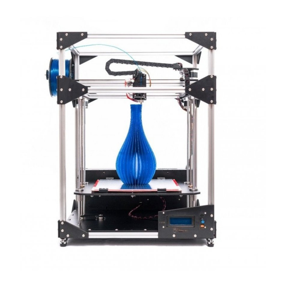
PRINTER FEATURES & DEFINITIONS The figure below shows the features of the Folger Tech FT-5 3D printer. You can reference this graphic for clarification of printer parts mentioned in this manual. Hotend Filament Spool Gantry Electronics cabinet Hotbed LCD Screen... -
Page 14: Power Supply
Gantry The gantry moves in the Y direction and has the Extruder mounted to it. Power Supply The power supply is what takes the 120 AC from the wall and converts it into 12v DC. FT-5 User Manual Page 13... - Page 15 Prepare – Option to setup a print (preheat hot end, auto home, cool down, etc.) Control – Change printer firmware settings (temperature, motion, and restore failsafe) Print from SD – Select a file to be printed FT-5 User Manual Page 14...
- Page 16 Auto Home – Zeros the machine and returns the effector to the home position Preheat PLA – Sets the hot end temperature to 200 °C and the bed to 70 °C Preheat ABS – Sets the hotend temperature to 230 °C and the bed to 100 °C FT-5 User Manual Page 15...
-
Page 17: Printer Assembly
PRINTER ASSEMBLY Construction of a Folger Tech FT-5 3D Printer is broken into 13 individual phases and sub-assemblies. The table below shows the different phases required to complete your 3D printer. Phase Assembly Description Page Assemble the Frame Assemble the Base Plate... -
Page 18: Assemble The Frame
1) ASSEMBLE THE FRAME In this section, the frame of the FT-5 printer will be assembled. You will need: Item ID Quantity Description 700mm 2020 Beam 500mm 2040 Beam 500mm 2020 Beam 460mm 2020 Beam Rubber Feet L Bracket FT25... - Page 19 Place the corner so that the bottom two T-nuts slide into the upper piece of the double AL beam. The end of the corner should line up with the end of the double AL beam. This is the left front of the printer. FT-5 User Manual Page 18...
- Page 20 Note this one will have the screws going through the opposite way. Insert the 700m 2020 beam down into all 4 M5 T-nuts. Tighten down the T-nuts and make sure the corner is tight together. FT-5 User Manual Page 19...
- Page 21 Using the same process before, add the top of the frame. Note that the sides use 460mm 2020 beams and the front uses 500mm 2020 beams. FT-5 User Manual Page 20...
- Page 22 12. Flip the frame over. Put a M5x10mm screw through a rubber foot and finish it off with a M5 T-nut. Attach this to one of the corners on the bottom. 13. Repeat step 12 for the remaining three corners. FT-5 User Manual Page 21...
-
Page 23: Assemble The Base Plate
Panel (the top side has the fan hole in the lower left). Secure the motor in place using four M3x10mm screws and four M3 washers. The motor wire connector should point towards the flower fan opening. Repeat the last step for the second stepper motor. FT-5 User Manual Page 22... - Page 24 Nylocks. Repeat step 4 for the other side of the base plate. With the face of the Bottom Panel pointing up, insert 18 M5 x 10mm screws and finish them off using 18 M5 T-nuts. FT-5 User Manual Page 23...
-
Page 25: Assemble The Top Plate
Insert M5x10mm screws into the remaining six holes and finish them off with six M5 T-nuts. The T-nuts should be on the same side as the rest of the T-nuts. Repeats steps 1-3 for the other Upper Panel. FT-5 User Manual Page 24... -
Page 26: Install Base And Top Plate
The 40mm fan should be in the back. Line up all the T-nuts and lock them into place. FT-5 User Manual Page 25... -
Page 27: Assemble Bed Plate
M3 Nylock. Insert T8 Leadscrew nut into the center holes and secure it in place using four M3x16mm Screws and four M3 Nylocks. Repeat this step for the other side of the hot bed plate. FT-5 User Manual Page 26... -
Page 28: Mounting Bed
The top of the chrome rod should slide into the upper SHF8. Tighten the screw on the SHF8 to lock the chrome rod in place. Repeat this for the other three M8 PCR. FT-5 User Manual Page 27... - Page 29 GT2 belts and insert them on the threaded rod. Thread the threaded rod through the bed plate and all the way to the KFL8 on the middle mounting bracket. Tighten the set screws on the bottom KFL8. FT-5 User Manual Page 28...
- Page 30 Ensure the belt is strait and tighten the screws on the stepper motor. Repeat steps 3-6 on the other threaded rod. FT-5 User Manual Page 29...
-
Page 31: Assemble Y Gantry Rails
Motor Right Take one of the slider rail, insert a M3x8mm screw into every other hole on the rail. Finish off each one with a M3 T-nut. Repeat step one for the remaining two slider rail. FT-5 User Manual Page 30... - Page 32 Line up the two rails and align the sliders with each other. Use some kapton tape to lock each one in place. This will prevent the slides from falling off while building and they will be cut free later. FT-5 User Manual Page 31...
- Page 33 Position the two rails parallel to each other. Set the two laser cut assemblies on top of each slider so that the Y belt holders are on the inside. Secure each one down using four M3x8mm screws. FT-5 User Manual Page 32...
-
Page 34: Gantry Assembly
Tighten the M5 screws to lock them onto the 500mm beam. The ends should be flush with the laser cut parts. This will be adjusted later to fit into the frame. FT-5 User Manual Page 33... - Page 35 M5x10mm screws through and finish them off with two M5 T-nuts. The lettering should be on the same side as the T-nuts. Place the stepper motor under the motor/right/middle. Use three M3x10mm screws to lock the motor in place. FT-5 User Manual Page 34...
- Page 36 Place the idler (2 bolt) on top of the 500mm 2020 beam and hold the idler pulley in between the two holes. The idler should be strait up and down. Lock the two T-nuts and secure the mount in place. FT-5 User Manual Page 35...
- Page 37 7 step 1 for details. 10. Put the stepper motor onto the 2020 beam and butt it up to the rail. The limit switch should be on the inside. Lock this in place using the two M5 screws. FT-5 User Manual Page 36...
-
Page 38: Hotend
Take the stepper motor and slide the brass drive gear onto the shaft of the motor. Leave a 1 mm gap between the stepper motor and the drive gear. Tighten the set screws on the drive gear. FT-5 User Manual Page 37... - Page 39 Secure this in place using a M3 setscrew. Screw on the 3D hotend onto the M6 tube. It may help to remove the heated core and the thermistor. FT-5 User Manual Page 38...
- Page 40 Place this over the X slide on the gantry and tighten the M3 screws down. Insert FT14 into the two slots on the FT11. Remove the two top screws on the back of the stepper motor. FT-5 User Manual Page 39...
- Page 41 10. Take FT9 and lay it face down. Take a female cable mount and secure it in place using two M3x12mm screws and two M3 Nylocks. FT-5 User Manual Page 40...
- Page 42 M3x12mm screw and two M3 Nylock. 12. Remove two of the screws from the back of the stepper motor. 13. Place FT9 over the back of the stepper motor. Secure it in place using two M3x40mm screws. FT-5 User Manual Page 41...
- Page 43 T-nuts, tighten the T-nuts and lock them in place. 17. Make sure the gantry moves smoothly. You may need to adjust the Y rails on the 2020 beams to make sure they are parallel to each other. FT-5 User Manual Page 42...
-
Page 44: Endstops And Belts
Y endstop Mount FT26 Idler (4 Bolts Left) 18. Take FT3 and insert four M5x10mm screws and finish them off using four M5 T-nuts. Repeat this for the other FT26. They should be mirror of each other. FT-5 User Manual Page 43... - Page 45 Take one end and lock it into the female cable mount on the x axis motor. Lock the other end onto the male cable mount on top of the hotend. FT-5 User Manual Page 44...
- Page 46 24. Take FT6 and secure an endstop using two M3x12mm screws and two M3 Nylocks. Insert a M5x10mm screw and finish it off using a M5 T- nut. FT-5 User Manual Page 45...
- Page 47 M3 Nylock. This will be adjusted during calibration. 28. Take the GT2 Belt and cut a one-meter length of it. Loop one end of it into the left Y-Belt. Use a zip tie to secure the loop. FT-5 User Manual Page 46...
- Page 48 Trim any excess belt. 32. Loosen the two screws on the stepper motor and pull so that the belt tightens. Tighten the two screws when the belt is tight. 33. Repeat steps 28-32 for the other Y Belt. FT-5 User Manual Page 47...
- Page 49 Use a zip tie to secure it in place and trim the excess. 37. Loosen the two M5 screws and pull the motor so that the belt is tight. Tighten these back down when the belt is tight. FT-5 User Manual Page 48...
-
Page 50: Mounting Electronics And Spool Mount
Spool Holder (T-Hut) Lay the power supply face down, and FT19 on top of it. Line up the four M4 holes on the back of the power supply and secure it in place using four M4x10mm screws. FT-5 User Manual Page 49... - Page 51 M3x16mm screws and two M3 square nuts. Place the power outlet onto FT20 and secure it in place using two M3x16mm screws and two M3 Nylocks. FT-5 User Manual Page 50...
- Page 52 M3x20mm screws, four nylon spacers, and four M3 Nylocks. Place the four larger nylon spacers between the LCD screen and FT25. Be careful not to over tighten the screws as this can damage the screen. FT-5 User Manual Page 51...
- Page 53 Insert the M5 threaded rod through and secure the whole thing in place using two M5 Nylocks. 11. Mount the spool holder on the back right vertical member. Between the top bracket and the middle one. FT-5 User Manual Page 52...
-
Page 54: Assemble And Mount Heated Bed
Note: If you have the white aluminum heated bed follow the same steps below without the aluminum plate. Cut the red wire in half and strip ¼ inch of each end. Solder on each wire to the heated bed. FT-5 User Manual Page 53... - Page 55 This will help prevent a contact between the wires and the AL print bed. Lay the bed over the bed platform, looping the wires down through one of the openings. FT-5 User Manual Page 54...
- Page 56 Secure each of the six hole locations with a M3x30mm screw, bed spring, and a M3 thumb screw. FT-5 User Manual Page 55...
-
Page 57: Wiring
Red (Right Motor ) /Green (Left Motor ) Take the 4 pin pigtail, and strip ¼ inch off the ends of each wire. Insert them into the other end of the 4 pin terminal as follows: Green, Yellow, Gray, Red. FT-5 User Manual Page 56... - Page 58 Looking at the bottom of the limit switch insert the four wires in the following order: Red, Black, Empty Space and Green. Take the last endstop cable and plug it into the Z axis endstop. FT-5 User Manual Page 57...
- Page 59 Pull the wire out. 11. It helps to remove the chain from the mounts for feeding wires through it. Feed the wire bundle and the stepper motor cable from the extruder to the x axis motor. FT-5 User Manual Page 58...
- Page 60 (left to right). Green, Green, Red, Black. Note that the green wires should line up with the two thermistor wires. The red and black wires should line up with the red and black wires from the extruder fan. FT-5 User Manual Page 59...
- Page 61 17. Insert the heater core and the thermistor into the Al heater block on the hotend. Secure them in place using the three set screws. Make sure not to tighten the thermistor down too much as this will damage the thermistor. FT-5 User Manual Page 60...
- Page 62 It will help to remove the chain when feeding wires through. 21. Pull the wires tight and take the time to organize them. This will be important during printing, so the cable will not snag on anything. FT-5 User Manual Page 61...
- Page 63 ¼ inch off the ends of each wire. Insert them into the other end of the 4 pin terminal as follows: Green, Gray, Yellow and Red 25. Plug in the two motor connectors into the Z stepper motors. FT-5 User Manual Page 62...
- Page 64 14 awg wire connects to pin 5. 28. On the front of the power outlet, remove the fuse panel. Insert one of the fuses into the fuse slot and the second fuse into the spare slot. Spare Fuse FT-5 User Manual Page 63...
- Page 65 Connect the red wires to the positive terminals on the power supply (there are three positive and negative terminals and each wire should have its own). Do the same for the black wires to the negative terminals. FT-5 User Manual Page 64...
- Page 66 If there is ever a need for access to 12v, use these terminals. 33. Plug in the four motor cables into the MKS board. The board is labeled with X Y Z E plug the cables into the corresponding holes. FT-5 User Manual Page 65...
- Page 67 37. Add the heatsinks to the five stepper motor drivers. Peel off the paper on the bottom and stick them on top of the main chip of the driver. Power should be off to the machine for this step!! FT-5 User Manual Page 66...
-
Page 68: Testing And Calibration
TESTING AND CALIBRATION Congratulations on successfully assembling your Folger Tech FT-5 3D Printer Kit! Now that it is built, it’s time to verify that all the components are working properly. This will require a computer and the USB cable that came with the printer. -
Page 69: Electronics Check List
Black, Red, Black, Red for the 2 big green plugs on the MKS board. 2. The thermistor wires should be plugged into the 1 and 2 connector. The top one should be the hot end and the bottom should be the heated bed. FT-5 User Manual Page 68... - Page 70 4. All of the stepper drivers should be pointing to the left (trim pot facing away from the power input plugs). 5. Verify that the fuse (250V 3A) has been inserted into the power outlet. FT-5 User Manual Page 69...
-
Page 71: Software
SOFTWARE The following software is used to test and run a Folger Tech FT-5 3D Printer. Arduino - Arduino is an open source hardware package that is attached to the underside of the base and is used to control the printer. The firmware running on Arduino is written in the Arduino programming language. -
Page 72: Verify The Endstops
Now that the printer is connected to the computer and it has recognized Arduino it’s time to open the Pronterface software. Open the Pronterface folder on the SD card, and select the Pronterface icon shown in the image below. We suggest copying the entire Pronterface folder onto your computer for later use. FT-5 User Manual Page 71... - Page 73 Send the “m119” command again in the bottom right corner. Verify the X endstop has triggered. Repeat this for the Y and Z endstop. It helps to do them individually in case they have been wired wrong. FT-5 User Manual Page 72...
-
Page 74: Verify Motor Direction And Homing
To verify that the motors are wired correctly, click on the home button on Pronterface. This will tell the gantry to move towards the home position. Note that at any time durring this step be ready to turn off the printer in case the gantry moves in the wrong direction during this process. FT-5 User Manual Page 73... -
Page 75: Adjusting Z Height
Scroll down until you find the Travel limits after homing then #define Z_MAX_POS. This is the value that will be adjusted to each printer. This is the value that is adjusted for the z height. FT-5 User Manual Page 74... -
Page 76: Verify The Hot End Temperature
230°C. If the bed temp is rising, then they are plugged in backwards. Set the bed temp to 100 and click the set button. Once the printer bed has reached temp and maintained it for a few minutes, press the off button. Before turning off the hot end, proceed to the next step “Verify the Extruder”. FT-5 User Manual Page 75... -
Page 77: Verify The Extruder
With the hot end at 230°C, click on the “Extrude” button on Pronterface. The extruder will not run if the hot end is under 170°C. Now the drive gear should turn in a clockwise direction. Turn off the hot end by clicking the “Off” button next to “Heat” on Pronterface. FT-5 User Manual Page 76... -
Page 78: Software Parameter Setup
Note: While Folger Tech recommends using Cura for slicing and G-code generation, other slicing software can be used. The printer parameters detailed below are a recommended for optimum performance of a Folger Tech printer, which can be used for other software. - Page 79 Click Next on the Configuration Wizard. FT-5 User Manual Page 78...
- Page 80 Under “Select your machine,” choose Other (Ex: RepRap, MakerBot, Witbox). Then click Next. Under “Other machine information,” select Custom and click Next. FT-5 User Manual Page 79...
- Page 81 Input the following values into the RepRap custom settings. Machine height was calculated in a previous section. FT-5 User Manual Page 80...
-
Page 82: Printing Settings
The parameters that are frequently adjusted to obtain the desire results for an individual part are found under the Basic Setting tab in Cura. The figure below shows the typical Basic tab settings for most prints. A detailed explanation of each parameter can be found below in the figure. FT-5 User Manual Page 81... - Page 83 Bed Temperature (°C): This is the temperature of the heated bed. ABS should be set too 100 °C and PLA should be set to 70 °C. Although PLA can be printed without the heated bed turned on. FT-5 User Manual Page 82...
- Page 84 2) Raft, which is a support structure under a print that helps secure it to the bed. A skirt is the initial pass that outlines a part to prepare the hot end for printing. FT-5 User Manual Page 83...
- Page 85 Flow (%): This describes the amount of filament being pushed through the nozzle. This value can be adjusted to optimize the quality of the print. A typical value is between 90-100 % for your FT-5 printer. If excessive plastic is being extruded, reduce this value by 5%.
- Page 86 Rotate - This function allows the part to be rotated inside the printer’s workable volume. To rotate a model, click on the rotate function in the lower left corner. Select the axis of rotation by selecting and holding the desired circle around the part. Drag the circle to change the orientation of the part. FT-5 User Manual Page 85...
- Page 87 Mirror – This function allows you to mirror the part about an axis. Click on the mirror icon in the lower left corner to activate this function. Select the desired axis to mirror part about. FT-5 User Manual Page 86...
-
Page 88: Generating G-Code Using Cura
STEP-BY-STEP PROCESS 1. Verify that FT-5 is selected under the Machine tab. 2. Load the desired model file (typically STL but CURA does accept other formats) by clicking on the Load icon in the top left of the print window. - Page 89 Note: Hovering the mouse over a setting will bring up a description of how the setting will affect the print. 5. Plug the printer into the computer into your computer. Click the print icon in the top left of the print window to connect Cura to your printer. FT-5 User Manual Page 88...
-
Page 90: Printing From An Sd Card
3) PRINTING FROM AN SD CARD The LCD screen allows the FT-5 3D Printer to read the G-code for your print file directly from an SD card. This allows the machine to run without being connected to a computer. -
Page 91: Printer Operation
3. Continue to feed the filament through the extruder and the Hotend until it flushes out the old filament from the nozzle. Release the extruder lever and you are now ready to get back to printing! Push Down Extruder Lever FT-5 User Manual Page 90... -
Page 92: Bed Preparation
(optional). If printing with ABS, apply a layer of glue (normal glue stick) over the area to be printed on. Allow this layer to dry before printing. FT-5 User Manual Page 91... -
Page 93: Maintenance
Ensure the filament is feeding correctly and being pushed into the nozzle from the extruder. Next, verify Plastic is not extruding from the nozzle. the nozzle temperature is correctly set between 210 °C for PLA and 230 C for ABS. FT-5 User Manual Page 92...
Need help?
Do you have a question about the FT-5 and is the answer not in the manual?
Questions and answers