
Related Manuals for Cobalt Digital Inc HPF-9000

Summary of Contents for Cobalt Digital Inc HPF-9000
- Page 1 HPF-9000 HPF-9000 High-Power 20-Slot Frame Product Manual Cobalt Digital Inc. 2506 Galen Drive Champaign, IL 61821 Voice 217.344.1243 • Fax 217.344.1245 www.cobaltdigital.com HPF9000-OM (V1.8)
- Page 2 Furthermore, Cobalt Digital Inc. reserves the right to make changes to any products herein to improve readability, function, or design. Cobalt Digital Inc. does not assume any liability arising out of the application or use of any product or circuit described herein.
-
Page 3: Important Safety Instructions
Important Safety Instructions Read these instructions. Keep these instructions. Heed all warnings. Follow all instructions. Do not use this apparatus near water. Clean only with a dry cloth. Warning Do not install near any heat sources such as radiators, heat registers, stoves, or other apparatus (including amplifiers) that produce heat. - Page 4 Changes or modifications to this equipment not expressly approved by Cobalt Digital Inc. could void the user's authority to operate this equipment.
-
Page 5: Table Of Contents
Installation and Setup ........Overview ........................ 2-1 HPF-9000 Controls and Indicators ................. 2-1 HPF-9000 Front Panel Controls and Indicators ......... 2-1 HPF-FC Network Controller Card Indicators ..........2-1 HPF9000-OM (V1.8) - Page 6 Installing the Frame....................2-3 HPF-9000 Dimensional Drawings .............. 2-3 Frame PSU Power Output Considerations ..........2-4 Ventilation Considerations................2-4 Status Reporting and Displays Considerations Using DashBoard™..2-5 Installing Frame in Rack ................2-5 Installing Frame Support Brackets.............. 2-6 Cable Connections ..................2-7 Power Supply Removal/Installation............
-
Page 7: Chapter 1 Introduction
Contact Cobalt Digital Inc. (p. 1-12) Manual Conventions In this manual, connectors are shown using the exact name shown on the HPF-9000 itself. In this manual, the terms below are applicable as follows: • ® HPF-9000 refers to the HPF-9000 frame that houses the Cobalt ®... -
Page 8: Warnings, Cautions, And Notes
Symbol (WEEE 2002/96/EC) For product disposal, ensure the following: • Do not dispose of this product as unsorted municipal waste. • Collect this product separately. • Use collection and return systems available to you. HPF-9000 PRODUCT MANUAL HPF9000-OM (V1.8) -
Page 9: Safety Summary
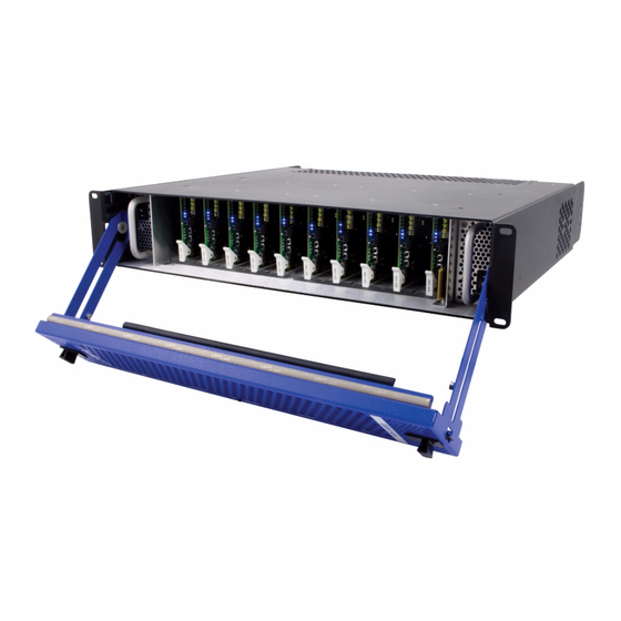
The HPF-FC Network Controller Card (furnished as standard on the HPF-9000 frame) allows Ethernet connectivity to any number of connections for full multi-point control and monitoring via free DashBoard™ software. The frame is equipped with two independent reference buses that can supply a selected reference to cards within the frame. - Page 10 Network Controller Card Card User Slot Area (20 User Slots Optional Redundant 360W Retractable Fan Power Supply (PSU2) Door (5 fans) Figure 1-1 HPF-9000 (Front View) Redundant Power Supply Primary Power Supply (PSU2) IEC AC (PSU1) IEC AC Line Connector Line Connector...
-
Page 11: Frame Rear I/O Modules
Rear I/O Modules are not sup- plied with the HPF-9000 frame. Cards within the frame physically interface to system video and audio connections using a Rear I/O Module. Figure 1-3 shows a typical Rear I/O Module. - Page 12 HPF-9000 Functional Description Split Rear Module Split Rear Module occupies 2 card slots, but also accommodates 2 card in adjacent slots. In this manner, for a frame fitted entirely with split rear modules, the maximum 20-card frame capacity can be achieved.
- Page 13 Introduction HPF-9000 Functional Description ® An Expansion Rear Module is used in conjunction with a Fusion3G card Expansion Rear Module equipped to provide optional connections such as analog audio I/O (which is in turn provided by an Expansion piggyback card factory-installed on the base card when ®...
-
Page 14: Frame Network Interface
• DashBoard™ User Interface – Using DashBoard™, all cards in the HPF-9000 Frame can be controlled from a computer and monitor. DashBoard™ allows users to view all frames on a network with control and monitoring for all populated slots inside a frame. This simplifies the setup and use of numerous modules in a large installation and offers the ability to centralize monitoring. - Page 15 Introduction HPF-9000 Functional Description OGCP-9000 Control Panel, OGCP-9000/CC Control Panel, and/or WinOGCP Virtual Control Panel(s) Remote Control Panel Using the Control Panel, cards are remotely controlled over a LAN 20-Slot Frame with Network Controller Card In conjunction with a frame equipped DashBoard™...
-
Page 16: Technical Specifications
Technical Specifications Technical Specifications Table 1-1 lists the technical specifications for the HPF-9000 Frame. Table 1-1 Technical Specifications Item Characteristic Part number, nomenclature HPF-9000 High-Power 20-Slot Frame (PN HPF-9000-CN) Includes one PSU-9000 Power Supply Module and HPF-FC Network Controller Card. -
Page 17: Warranty And Service Information
(1) year. Cobalt Digital Inc.'s (“Cobalt”) sole obligation under this warranty shall be limited to, at its option, (i) the repair or (ii) replacement of the product, and the determination of whether a defect is covered under this limited warranty shall be made at the sole discretion of Cobalt. -
Page 18: Contact Cobalt Digital Inc
Contact Cobalt Digital Inc. Contact Cobalt Digital Inc. Feel free to contact our thorough and professional support representatives for any of the following: • Name and address of your local dealer • Product information and pricing • Technical support •... -
Page 19: Chapter 2 Installation And Setup
Using a Log for Managing Frames (p. 2-31) HPF-9000 Controls and Indicators HPF-9000 Front Panel Controls and Indicators Figure 2-1 shows and describes the HPF-9000 front panel controls and indicators. HPF-FC Network Controller Card Indicators Figure 2-1 shows and describes the HPF-FC card-edge indicators. - Page 20 Switch FAN FAULT When lit, indicates a fan on the frame door or PSU is stalled, or that fan door is not fully closed and latched. Indicator Figure 2-1 HPF-9000 Front Panel Controls and Indicators Item Function OK LED When lit, card has no detected errors and is receiving power properly.
-
Page 21: Installing The Frame
Installation and Setup Installing the Frame Installing the Frame HPF-9000 Dimensional Drawings Figure 2-3 shows the installation dimensional details for the HPF-9000 frame (all dimensions in inches). Figure 2-3 HPF-9000 Dimensional Drawings HPF9000-OM (V1.8) HPF-9000 PRODUCT MANUAL... -
Page 22: Frame Psu Power Output Considerations
Installing the Frame Frame PSU Power Output Considerations • The HPF-9000 uses power supply units (PSUs) that provide a 400 W capacity per each supply. Note that with redundant supplies, the power delivery may not be exactly split between the two supplies. The maximum... -
Page 23: Status Reporting And Displays Considerations Using Dashboard
Installing Frame in Rack For normal installations, the HPF-9000 is designed to be supported in a standard EIA-310 19” rack by securing the frame by its four front panel mounting holes only, without added rear support. Select an installation location within the rack considering Ventilation Considerations above. -
Page 24: Installing Frame Support Brackets
19” rack rear frame rails. This kit is recommended for any cases where the frame is to be used in mobile applications, including trucks or equipment cases. Install the support brackets to each side of the HPF-9000 frame as shown in Figure 2-4. Position bracket rail on side of HPF-9000 frame and align small holes with 5 threaded holes on frame. -
Page 25: Cable Connections
Connector Card Rear I/O Modules Connectors Figure 2-5 HPF-9000 Rear View Each power supply is equipped with its own power switch (located on the front of the power supply). With the switch set to the up position, the power supply is turned on (as verified by the green LED adjacent to the switch). -
Page 26: Power Supply Removal/Installation
Loosen the retaining screw to allow card removal. Reverse this procedure to install and lock the card in its slot. Network Controller Card Setup DIP Switch Card Retainer Screw Figure 2-6 Network Controller Card HPF-9000 PRODUCT MANUAL HPF9000-OM (V1.8) -
Page 27: Installing Rear I/O Modules And Cards
I/O Module with the module seating slot on rear of frame chassis. Hold top of Rear I/O Module flush against frame chassis and start the captive screw. Lightly tighten captive screw. Figure 2-7 Rear I/O Module Installation HPF9000-OM (V1.8) HPF-9000 PRODUCT MANUAL... -
Page 28: User Card Installation
If card resists fully engaging in Rear I/O Module mating connector, check for alignment and proper insertion in slot tracks. Damage to card and/or Rear I/O Module may occur if improper card insertion is attempted. Repeat for other cards. 2-10 HPF-9000 PRODUCT MANUAL HPF9000-OM (V1.8) -
Page 29: Setting Up Network Remote Control
Installation and Setup Setting Up Network Remote Control Setting Up Network Remote Control The HPF-9000 frame and its HPF-FC Network Controller Card uses a standard 100/1000 Mbps Ethernet LAN for communication between the ® frame containing the Cobalt cards and the computer running DashBoard™... -
Page 30: Frame Setup Using Dhcp
On the computer connected to the frame LAN, go to the Cobalt Digital Inc. website: www.cobaltdigital.com and download DashBoard™. Follow the on-line instructions. Open DashBoard™. Under Window Preferences... make certain Automatic discovery of devices Enable button is selected (as shown below). SETUP_AUTODISC.PNG 2-12 HPF-9000 PRODUCT MANUAL HPF9000-OM (V1.8) - Page 31 IP address assigned by DHCP server Connect the frame to the LAN. Install the network card in the frame and power-up the frame. Wait for the network card to fully boot (red LED turns off). 2-13 HPF9000-OM (V1.8) HPF-9000 PRODUCT MANUAL...
- Page 32 ® Cobalt are identified in DashBoard™ by the card part number as shown in the examples in this section; therefore, no other action needs to be done unless a custom unique name is desired. 2-14 HPF-9000 PRODUCT MANUAL HPF9000-OM (V1.8)
- Page 33 IP address other than the card fixed default (“10.99.11.51” in this example) making certain the selected address is in the same subnet as the Network Controller card and LAN host computer. configuration pane, click Apply. Network 2-15 HPF9000-OM (V1.8) HPF-9000 PRODUCT MANUAL...
-
Page 34: Frame Setup Using Static Ip Address
If static IP addresses are to be used, carefully follow this procedure. If the pro- cedure is not followed as specified, DashBoard™ may lose all communication with the frame, thereby requiring the procedure to be repeated in its entirety. 2-16 HPF-9000 PRODUCT MANUAL HPF9000-OM (V1.8) - Page 35 Set Network Computer for Static IP Addressing As shown below, set the frame LAN computer to add static IP addressing that is on the same network as the network card default static IP address 192.168.2.x 2-17 HPF9000-OM (V1.8) HPF-9000 PRODUCT MANUAL...
- Page 36 Set network card DIP switch to the factory fixed static IP address position as shown below. This establishes the initial connection between the card and the network computer. MFC8320_PCB.JPG Rear of Card 8320 factory fixed IP address 192.168.2.1 2-18 HPF-9000 PRODUCT MANUAL HPF9000-OM (V1.8)
- Page 37 The added frame should now appear in the Basic Tree View pane. If necessary, right-click on the frame and select Connect. The frame is now connected to DashBoard™. Frame added in DashBoard™ DB_ACCESS1A.PNG Frame now connected in DashBoard™ DB_ACCESS1.PNG 2-19 HPF9000-OM (V1.8) HPF-9000 PRODUCT MANUAL...
- Page 38 DashBoard™. Re-insert the card. When the card again comes online, the frame now shows connection to DashBoard™ with the assigned static IP address (“10.99.16.103” as shown in the example on the next page). 2-20 HPF-9000 PRODUCT MANUAL HPF9000-OM (V1.8)
-
Page 39: Network Controller Card Address Mode Switch
Local/private Static IP address IP address IP address set to assigned by assigned by factory fixed factory: address set to user DHCP 192.168.2.1 fixed factory: 10.1.2.1 Figure 2-8 Network Controller Card DIP Switch Overview 2-21 HPF9000-OM (V1.8) HPF-9000 PRODUCT MANUAL... -
Page 40: Setting Network Controller Card/Frame User Access
Setting DIP switch position 3 to ON or OFF allows password password access to access (override) and override as shown. be applied allow full access to the frame 2-22 HPF-9000 PRODUCT MANUAL HPF9000-OM (V1.8) -
Page 41: Setting Network Controller Card To Mute Audible Alarms
HFC-FC network controller card provides several status display and auxiliary function setup interfaces as described below. Frame Info Tabs The left pane of the network Controller Card DashBoard page provides a status display as shown in Figure 2-9. 2-23 HPF9000-OM (V1.8) HPF-9000 PRODUCT MANUAL... - Page 42 Controller Card to Mute Audible Alarms (p. 2-23) for more information. Frame Model - S/N shows frame model number and S/N. (If network card is installed in a frame other than HPF-9000, “unknown” will be displayed.) Frame Voltage/Power shows frame rail voltages and positivce rail total power consumed.
-
Page 43: Frame Setup And Auxiliary Function Control Tabs
Note: • DashBoard may need Refresh for custom names to appear. • Custom names will only appear in other DashBoard connections where a card is installed in the slot with the custom name. • • • 2-25 HPF9000-OM (V1.8) HPF-9000 PRODUCT MANUAL... - Page 44 Cobalt Support. It is recommended to leave this default setting enabled so that your installation is visible should it need analysis by Cobalt Support. 2-26 HPF-9000 PRODUCT MANUAL HPF9000-OM (V1.8)
- Page 45 Note: All known instances of Cobalt openGear cards support network controller card parameter caching. If card will not appear, set Parameter Caching to Disabled. This mode is the same as previous frame network controller card function. 2-27 HPF9000-OM (V1.8) HPF-9000 PRODUCT MANUAL...
- Page 46 • Door Open – checks that fan door is fully latched and allows escalations settings and audible alarm trigger select. • Fan Stalled – checks for acknowledge of operation for all door fans and allows escalations settings and audible alarm trigger select. 2-28 HPF-9000 PRODUCT MANUAL HPF9000-OM (V1.8)
-
Page 47: Troubleshooting Network/Remote Control Errors
• Make certain this Network Card or others have not been left with its address mode switch set to the factory fixed static IP address mode. 2-29 HPF9000-OM (V1.8) HPF-9000 PRODUCT MANUAL... - Page 48 LAN. Check the following: • Make certain the Ethernet cable is properly connected and showing activity on the LAN switch. Use ping to check the connection. 2-30 HPF-9000 PRODUCT MANUAL HPF9000-OM (V1.8)
-
Page 49: Using A Log For Managing Frames
DashBoard™. The form is equipped with on-line form fields that allow the form to be filled out as a PDF soft copy. Save the ® ® form page using the Adobe Acrobat save options. 2-31 HPF9000-OM (V1.8) HPF-9000 PRODUCT MANUAL... - Page 50 FAULT LED) button on the Setup tab. This causes the connected frame’s front panel/door FAULT LED to flash and its beeper to sound (as long as beeper jumper is not set to Mute). 2-32 HPF-9000 PRODUCT MANUAL HPF9000-OM (V1.8)
- Page 51 ❏ DHCP ❏ Static IP ADDR: Netmask: Gateway: ❏ DHCP ❏ Static IP ADDR: Netmask: Gateway: ❏ DHCP ❏ Static IP ADDR: Netmask: Gateway: © 2009 Cobalt Digital Inc. All Rights Reserved. Form FLF1 (V1.0) 2-33 HPF9000-OM (V1.8) HPF-9000 PRODUCT MANUAL...
- Page 52 This page intentionally blank 2-34 HPF-9000 PRODUCT MANUAL HPF9000-OM (V1.8)
- Page 54 Cobalt Digital Inc. 2605 Galen Drive. Champaign, IL 61821 Voice 217.344.1243 • Fax 217.344.1245 www.cobaltdigital.com HPF9000-OM (V1.8) Printed in USA...
Need help?
Do you have a question about the HPF-9000 and is the answer not in the manual?
Questions and answers