Table of Contents
Advertisement
Quick Links
PNEUMERCATOR
Liquid Level Control Systems
Peter Sinkiwskij
Date: 2018.02.12 12:32:22 -05'00'
email=peter@pneumercator.com, c=US
Co., Inc., ou=Headquarters,
DN: cn=Peter Sinkiwskij, o=Pneumercator
Digitally signed by Peter Sinkiwskij
MAINTENANCE MANUAL
MODEL TMS2000 and TMS3000
© COPYRIGHT 2018 PNEUMERCATOR CO., INC.
TMS Operations and Maintenance Manual.docx
OPERATION &
(Covers Firmware versions Vxx.99.xx, Vxx.00.xx, and Vxx.01.xx)
(Vxx.00.58 and Vxx.01.17 firmware versions referenced for manual)
1785 EXPRESSWAY DRIVE NORTH
HAUPPAUGE, NY 11788
TEL: (631) 293-8450
FAX: (631) 293-8533
http://www.pneumercator.com
MULTI TANK
MONITORING
SYSTEM
DRAWING NO. 20001 REV. A
February 12, 2018
Advertisement
Table of Contents

Related Manuals for Pneumercator TMS2000


Summary of Contents for Pneumercator TMS2000
- Page 1 DRAWING NO. 20001 REV. A MODEL TMS2000 and TMS3000 (Covers Firmware versions Vxx.99.xx, Vxx.00.xx, and Vxx.01.xx) (Vxx.00.58 and Vxx.01.17 firmware versions referenced for manual) © COPYRIGHT 2018 PNEUMERCATOR CO., INC. 1785 EXPRESSWAY DRIVE NORTH HAUPPAUGE, NY 11788 TEL: (631) 293-8450 FAX: (631) 293-8533 http://www.pneumercator.com...
-
Page 3: Table Of Contents
OPERATION & MAINTENANCE MANUAL TMS2000/3000 Note: Refer to the model-specific INSTALLATION MANUAL for complete installation details. TABLE OF CONTENTS Page Section SYSTEM OVERVIEW Front Panel Description ........................5 Display .............................. 6 Audible Annunciator .......................... 6 Section OPERATION Power-Up Sequence ......................... 7 Overview of Operating Modes/System Function Tree .............. -
Page 5: Front Panel Description
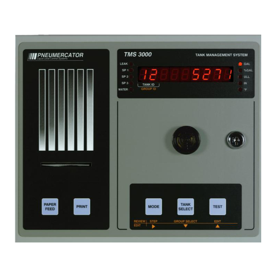
OPERATION & MAINTENANCE MANUAL TMS2000/3000 SECTION 1 – SYSTEM OVERVIEW 1.1 FRONT PANEL DESCRIPTION The front panel of the TMS is available in four different configurations as listed below: -1... Console without LED display, without internal printer -2... Console with LED display, without internal printer -3... -
Page 6: Display
OPERATION & MAINTENANCE MANUAL TMS2000/3000 1.2 DISPLAY The front panel display consists of a nine-digit, seven-segment, quasi-alphanumeric super bright LED display, providing on site viewing of current inventory data, alarms, errors, report logs, as well as, set-up and configuration data. Five high intensity point LEDs annunciate alarm conditions visible up to 75 feet or 25 meters away from console. -
Page 7: Section 2 Operation 2.1 Power-Up Sequence
OPERATION & MAINTENANCE MANUAL TMS2000/3000 SECTION 2 – OPERATION 2.1 POWER-UP SEQUENCE Upon application of AC power, the TMS performs a series of tasks prior to normal operation. These include the following: 1. A self-test to verify integrity of both system program and data memories, system I/O, and data acquisition interface electronics. -
Page 8: Overview Of Operating Modes/System Function Tree
OPERATION & MAINTENANCE MANUAL TMS2000/3000 2.2 OVERVIEW OF OPERATING MODES/SYSTEM FUNCTION TREE TMS front panel operation is defined by three user-selectable modes, View, Test, and Access, all selected using the MODE and TEST pushbuttons. See Figure 2.2, System Function Tree below. -
Page 9: View Mode Details
OPERATION & MAINTENANCE MANUAL TMS2000/3000 2.3 VIEW MODE DETAILS Looking at the names assigned to the console front panel pushbuttons and display field, note that some appear in white lettering, others in orange. Only the black or white-lettered name assignments apply to the VIEW mode. - Page 10 OPERATION & MAINTENANCE MANUAL TMS2000/3000 See below: Actual TMS Visual representation of Front Panel displayed items, in order of appearance: 2. 2 . 8 . 8 . %GAL Gross Volume = 10679 Gallons, Tank 2 TANK ID GROUP ID °F 2.
-
Page 11: Access Mode
OPERATION & MAINTENANCE MANUAL TMS2000/3000 2.4 ACCESS MODE DETAILS ANALOG OUTputs in- TANK LEAK tes t DIAL OUT MODEM THEFT INVENTORY SENSoR INPu t CC INPUT RELaY MODE RELaY SITE RELaY Line Leak Pane l EVENTS RELaY SENSor ALARMS INITialize D ATA... - Page 12 OPERATION & MAINTENANCE MANUAL TMS2000/3000 ENTERING ACCESS MODE The ACCESS mode is entered by first pressing and holding TEST, and then, while still holding TEST, simultaneously pressing and holding MODE. After approximately two seconds, the TMS will enter ACCESS mode. The display will...
- Page 13 OPERATION & MAINTENANCE MANUAL TMS2000/3000 EDIT: The EDIT pushbutton is used to edit or change the value of the currently displayed data item. If the displayed item is a menu or sub-menu name, EDIT allows the user to change the menu. If the displayed item is system data, for example, configuration or clock data, the EDIT function is inhibited unless enabled by the EDIT ENABLE pushbutton located on the inside of the front panel.
- Page 14 Initial application of AC power to this system should occur only after complete verification of safe, proper installation by authorized Pneumercator certified service personnel. Failure to do so may result serious injury and/or property damage. TMS Operations and Maintenance Manual.docx...
- Page 15 OPERATION & MAINTENANCE MANUAL TMS2000/3000 POWER-UP SEQUENCE: Upon application of AC power, the TMS performs a series of tasks prior to normal operation. These include in the following sequence: 1) A self-test to verify integrity of both system program and data memories, system I/O, and data acquisition interface electronics.
-
Page 16: Logs
OPERATION & MAINTENANCE MANUAL TMS2000/3000 2.4.1 LOGS ACCESS System reports LEAK test Leak test setup Config System configuration Clock Set system clock Init data Resets data to initialized values Return Exits access menu System Logs/Reports: The LOG menu contains various Logs/Reports that are primarily a grouping of historical recorded events that have been captured and stored in the TMS memory. -
Page 17: Shift Inventory
OPERATION & MAINTENANCE MANUAL TMS2000/3000 2.4.1.1 SHIFT INVENTORY LOG Inventory Inventory Scheduled inventory snaphots deLivery Deliveries Product delivered to storage tank SALES Bulk Sales Product sold from storage tank tHEFtS Thefts Unauthorized withdrawal from tank Orders Product Reordering Report Product reordering report... -
Page 18: Delivery
OPERATION & MAINTENANCE MANUAL TMS2000/3000 2.4.1.2 DELIVERY LOG Inventory Inventory deLivery Deliveries SALES Bulk Sales tHEFtS Thefts Orders Product Reordering Report Water Bottom Water Removal In-Tank Leak Test – Detailed Results tank Leak In-Tank Leak Test – History Leak Hist... -
Page 19: Bulk Sales
OPERATION & MAINTENANCE MANUAL TMS2000/3000 2.4.1.3 BULK SALES LOG Inventory Inventory deLivery Deliveries SALES Bulk Sales tHEFtS Thefts Orders Product Reordering Report Water Bottom Water Removal In-Tank Leak Test – Detailed Results tank Leak In-Tank Leak Test – History Leak Hist... -
Page 20: Thefts
OPERATION & MAINTENANCE MANUAL TMS2000/3000 2.4.1.4 THEFTS LOG Inventory Inventory deLivery Deliveries SALES Bulk Sales tHEFtS Thefts Orders Product Reordering Report Water Bottom Water Removal In-Tank Leak Test – Detailed Results tank Leak In-Tank Leak Test – History Leak Hist... -
Page 21: Product Reordering Report
OPERATION & MAINTENANCE MANUAL TMS2000/3000 2.4.1.5 PRODUCT REORDERING REPORT Inventory Inventory deLivery Deliveries SALES Bulk Sales tHEFtS Thefts Orders Product Reordering Report Water Bottom Water Removal In-Tank Leak Test – Detailed Results tank Leak In-Tank Leak Test – History Leak Hist... -
Page 22: Bottom Water Removal
OPERATION & MAINTENANCE MANUAL TMS2000/3000 2.4.1.6 BOTTOM WATER REMOVAL REPORT Inventory Inventory deLivery Deliveries SALES Bulk Sales tHEFtS Thefts Orders Product Reordering Report Water Bottom Water Removal In-Tank Leak Test – Detailed Results tank Leak In-Tank Leak Test – History... - Page 23 OPERATION & MAINTENANCE MANUAL TMS2000/3000 2.4.1.7 IN-TANK LEAK TEST – DETAILED RESULTS Inventory Inventory deLivery Deliveries SALES Bulk Sales tHEFtS Thefts Orders Product Reordering Report Water Bottom Water Removal In-Tank Leak Test – Detailed Results tank Leak In-Tank Leak Test – History...
- Page 24 OPERATION & MAINTENANCE MANUAL TMS2000/3000 2.4.1.8 IN-TANK LEAK TEST – HISTORY LOG Inventory Inventory deLivery Deliveries SALES Bulk Sales tHEFtS Thefts Orders Product Reordering Report Water Bottom Water Removal In-Tank Leak Test – Detailed Results tank Leak In-Tank Leak Test – History...
- Page 25 OPERATION & MAINTENANCE MANUAL TMS2000/3000 2.4.1.9 LS300 LINE LEAK TEST LOG Inventory Inventory deLivery Deliveries SALES Bulk Sales tHEFtS Thefts Orders Product Reordering Report Water Bottom Water Removal In-Tank Leak Test – Detailed Results tank Leak In-Tank Leak Test – History...
-
Page 26: Alarms
OPERATION & MAINTENANCE MANUAL TMS2000/3000 2.4.1.10 ALARMS LOG Inventory Inventory deLivery Deliveries SALES Bulk Sales tHEFtS Thefts Orders Product Reordering Report Water Bottom Water Removal In-Tank Leak Test – Detailed Results tank Leak In-Tank Leak Test – History Leak Hist... -
Page 27: Events
OPERATION & MAINTENANCE MANUAL TMS2000/3000 2.4.1.11 EVENTS LOG Inventory Inventory deLivery Deliveries SALES Bulk Sales tHEFtS Thefts Orders Product Reordering Report Water Bottom Water Removal In-Tank Leak Test – Detailed Results tank Leak In-Tank Leak Test – History Leak Hist... - Page 28 OPERATION & MAINTENANCE MANUAL TMS2000/3000 Event log reports may contain any combination of the following data: EVENT CONDITIONS Errors: Codes: System Boot Prom Checksum (U4 socket) Flash Prom Checksum (U5 socket) Flash Prom Write (U5 socket) Flash Prom Erase (U5 socket)
-
Page 29: In-Tank Leak Test Scheduling
8 hour, 0.2 GPH [0.8 LPH] Test for USTs up to 75,000 Gallons [283,900 Liters] with a Minimum Percent of used volume of 50% Refer to the National WorkGroup website, www.nwglde.org, or contact Pneumercator for up to date information. Entry Type: select list... - Page 30 OPERATION & MAINTENANCE MANUAL TMS2000/3000 Schd rate Schedule Rate: Applies to configured Test Type of Timed and Timed-Relay and is used in conjunction with Start Time, Schedule Type, and Schedule Day to define the complete schedule. Examples of how these settings interact are provided at the end of this section...
- Page 31 OPERATION & MAINTENANCE MANUAL TMS2000/3000 Scheduling the leak test The leak test scheduling can be found in the LEAK TEST menu. This allows you to determine how long to run the test, as well as, when the test will start. The scheduling features are used with the TIME and RELAY modes of operation.
- Page 32 OPERATION & MAINTENANCE MANUAL TMS2000/3000 TEST LENGTH START TIME SCHEDULE TYPE SCHEDULE RATE 4) Perform a 2 HOUR test at 00:00 THIS SUNDAY 4 HOUR EVERY MONDAY 8 HOUR PERCENT VOLUME TUESDAY ON 1 WEDNESDAY ON 2 THURSDAY ON 3...
-
Page 33: Configuration
OPERATION & MAINTENANCE MANUAL TMS2000/3000 2.4.3 SYSTEM CONFIGURATION ACCESS LEAK test Config Clock Init data Return In view mode depressing Test button first, then Mode and holding both buttons momentarily will increment the TMS into the ACCESS MODE displaying the main menu beginning as follows with Log. Pressing the Test button again will increment to the LEAk test menu and then to the Config menu. -
Page 34: Header
OPERATION & MAINTENANCE MANUAL TMS2000/3000 2.4.3.1 SYSTEM CONFIGURATION – HEADER ConFig Header – General System Settings Header Tank – Tank Channel specific including geometry and SetPoints tank Probe – Level Gauging Probe settings Probe – ReLy tank Relay Tank Relay Assignments to Tank Channel Specific conditions Relay CC –... - Page 35 OPERATION & MAINTENANCE MANUAL TMS2000/3000 Dsp Mode Default Display Mode: The TMS will return to the Default Display Mode when no buttons are pressed for approximately four minutes. Entry Type: select list Range Limits: Gr Vol: Gross Volume in Gallons/Liters...
- Page 36 OPERATION & MAINTENANCE MANUAL TMS2000/3000 SP1 LED Product SetPoint LED assignment: (6 Product SetPoint Firmware Only: Vxx01xx). Selects SP2 LED which of the six Product SetPoints are mapped to which of the three SP LEDs on the TMS SP3 LED Display.
- Page 37 OPERATION & MAINTENANCE MANUAL TMS2000/3000 tms Proto TMS Protocol: Current TMS systems report Water Volume via all communications interfaces (N2 Protocol). Select third-party systems that are not compatible with this revision to the response require the TMS to respond as was originally designed to exclude water volume (N1 Protocol).
-
Page 38: Tank
OPERATION & MAINTENANCE MANUAL TMS2000/3000 2.4.3.2 SYSTEM CONFIGURATION – TANK Config Header – General System Settings Header Tank – Tank Channel specific including geometry and SetPoints tank Probe – Level Gauging Probe settings Probe – ReLy tank Relay Tank Relay Assignments to Tank Channel Specific conditions Relay CC –... - Page 39 OPERATION & MAINTENANCE MANUAL TMS2000/3000 User Name User-Defined Tank Name: A 6-character alphanumeric name entered via TMSComm. Note that this is a context sensitive setting that only appears if the Tank Name is set for User Entry Type: select list Range Limits: 6-character alphanumeric.
- Page 40 OPERATION & MAINTENANCE MANUAL TMS2000/3000 ******************************************************************************************************** The next group of settings pertain to 3 Product SetPoint Firmware Only (Vxx99xx or Vxx00xx) and are used to configure the numbered Product SetPoints. SP1 P VoL Product SetPoint (Percent Volume): A Product SetPoint represents a range defined as a SP2 P VoL combination of two values: (1) the threshold is a numeric value that defines the percent volume SP3 P VoL that must be met or exceeded to be considered in alarm and (2) the direction of over (>) or...
- Page 41 OPERATION & MAINTENANCE MANUAL TMS2000/3000 ******************************************************************************************************** The next group of settings pertain to 6 Product SetPoint Firmware Only (Vxx01xx) and are used to configure the numbered Product SetPoints. Crit High Product SetPoint Activation Thresholds: A Product SetPoint represents a range defined as a...
- Page 42 This setting is also used as part of a Pump Auto Select feature where the TMS would select the pump associated with the tank with the greatest volume. Contact Pneumercator for a separate application document for the Pump Auto Select feature.
- Page 43 OPERATION & MAINTENANCE MANUAL TMS2000/3000 tank rise Tank Rise: Represents the degree of tilt over the entire length of the tank. Applies to Flat and Custom 3 Tank Types. This value is entered in Level units (inches/millimeters) and represents the difference between the low and high end of the tank. See below illustration for complete details.
- Page 44 Volume # menu item. Evenly spacing the heights may result in accurate readings for tank with minor symmetry problems. For more substantial differences, contact Pneumercator for guidance. Entry Type: 5-digit numeric Range Limits: 0 – 1999.9 inches [0 – 49,999 millimeters] Default/Initialized value: 0.
-
Page 45: Probe
OPERATION & MAINTENANCE MANUAL TMS2000/3000 2.4.3.3 SYSTEM CONFIGURATION – PROBE Config Header – General System Settings Header Tank – Tank Channel specific including geometry and SetPoints tank Probe – Level Gauging Probe settings Probe – ReLy tank Relay Tank Relay Assignments to Tank Channel Specific conditions Relay CC –... - Page 46 OPERATION & MAINTENANCE MANUAL TMS2000/3000 h2o HO Bottom Water Height Float Offset: Represents the adjustment to the raw probe level required to compensate for both the float depth in the liquid and mounting height of the probe. Required to provide accurate bottom water volume calculations. Calculated by taking the difference between the raw probe level and a manual stick reading of the bottom water level.
- Page 47 OPERATION & MAINTENANCE MANUAL TMS2000/3000 Riser gpi Riser GPI (LPI): Represents the collective volume of the riser pipes above the O/W Separator. This context sensitive setting is only visible if the Probe Type is set for MP452. Entry Type: 5-digit numeric Range Limits: 0 –...
- Page 48 The TMS3000 currently supports up to 32 Relay Outputs and the TMS2000 systems currently support up to 18 Relay Outputs. The Group ID shown corresponds to the hardware Tank Channel and NOT the Tank ID.
- Page 49 The TMS3000 currently supports up to 32 Relay Outputs and the TMS2000 systems currently support up to 18 Relay Outputs. The Group ID shown corresponds to the Non-Hazardous Contact Closure (CC) Input Number.
- Page 50 ReLy sens Relay – Sensor (ISCC) Input Triggers: Each Leak/Point Level Sensor (ISCC) Input can affect up to three relay outputs. The TMS3000 currently supports up to 32 Relay Outputs and the TMS2000 systems currently support up to 18 Relay Outputs. The Group ID shown corresponds to the Leak/Point Level Sensor Input Number.
- Page 51 LS300 Line Leak Panel (LLP) can affect up to three relay outputs. The TMS3000 currently supports up to 32 Relay Outputs and the TMS2000 systems currently support up to 18 Relay Outputs. The Group ID shown corresponds to the hardware channel for the LS300 Line Leak Panel.
- Page 52 ReLy Site Relay – Site-Specific Conditions: The TMS can report select conditions are specific to the Site and not necessarily a specific probe or sensor. Each site-specific condition can affect up to three relay outputs. The TMS3000 currently supports up to 32 Relay Outputs and the TMS2000 systems currently support up to 18 Relay Outputs.
-
Page 53: Relay Mode
OPERATION & MAINTENANCE MANUAL TMS2000/3000 2.4.3.9 SYSTEM CONFIGURATION – RELAY MODE Config Header – General System Settings Header Tank – Tank Channel specific including geometry and SetPoints tank Probe – Level Gauging Probe settings Probe – ReLy tank Relay Tank Relay Assignments to Tank Channel Specific conditions Relay CC –... - Page 54 Entry Type: select list Range Limits: Tank NO: Specified Latch Off condition NOT selected Tank 1-12 (TMS3000), Tank 1-2 (TMS2000) Default/Initialized value: tnk no CritH OFF SetPoint # Latch Off: (6 Product SetPoint Firmware Only: Vxx01xx). Identifies the Tank Channel...
- Page 55 Trigger Groups: Part of a Pump Auto Select feature where the TMS would select the pump associated with the tank with the greatest volume. Contact Pneumercator for a separate application document for the Pump Auto Select feature. Default/Initialized value: OFF...
- Page 56 OPERATION & MAINTENANCE MANUAL TMS2000/3000 Inp Name Input Name: Name of CC Input specified to identify function of CC Input. The name USER indicates a User-Defined CC Input Name. See next setting for User-Defined Name. Entry Type: select list Range Limits: See table below...
- Page 57 OPERATION & MAINTENANCE MANUAL TMS2000/3000 2.4.3.11 SYSTEM CONFIGURATION – SENSOR INPUT Config Header – General System Settings Header Tank – Tank Channel specific including geometry and SetPoints tank Probe – Level Gauging Probe settings Probe – ReLy tank Relay Tank Relay Assignments to Tank Channel Specific conditions Relay CC –...
- Page 58 Leak light and integrated horn. Entry Type: select list Range Limits: Tank NO: Sensor NOT Associated with Tank Channel Tank 1-12 (TMS3000), Tank 1-2 (TMS2000) Default/Initialized value: tnk no Associate Associate with Dispenser: Supplements the Sensor Name for the purpose of locating the sensor by identifying the Dispenser Pan the sensor is installed in.
-
Page 59: Inventory
OPERATION & MAINTENANCE MANUAL TMS2000/3000 2.4.3.12 SYSTEM CONFIGURATION – INVENTORY Config Header – General System Settings Header Tank – Tank Channel specific including geometry and SetPoints tank Probe – Level Gauging Probe settings Probe – ReLy tank Relay Tank Relay Assignments to Tank Channel Specific conditions Relay CC –... - Page 60 OPERATION & MAINTENANCE MANUAL TMS2000/3000 Hour 3 Hour 3: The TMS will record an Inventory Snaphot for every unique time configured in HOUR 1, HOUR 2, and HOUR 3 for the enabled Days of the Week. See Hour 1 example.
-
Page 61: Theft
OPERATION & MAINTENANCE MANUAL TMS2000/3000 2.4.3.13 SYSTEM CONFIGURATION – THEFT Config Header – General System Settings Header Tank – Tank Channel specific including geometry and SetPoints tank Probe – Level Gauging Probe settings Probe – ReLy tank Relay Tank Relay Assignments to Tank Channel Specific conditions Relay CC –... -
Page 62: Modem
OPERATION & MAINTENANCE MANUAL TMS2000/3000 2.4.3.14 SYSTEM CONFIGURATION – MODEM Config Header – General System Settings Header Tank – Tank Channel specific including geometry and SetPoints tank Probe – Level Gauging Probe settings Probe – ReLy tank Relay Tank Relay Assignments to Tank Channel Specific conditions Relay CC –... - Page 63 OPERATION & MAINTENANCE MANUAL TMS2000/3000 PAUSE Pause Length: Supports the Dial-Out function. Defines the number of seconds a single Pause or comma represents in the dial-out string. Entry Type: 1-digit numeric, seconds Range Limits: 1-9 Seconds Default/Initialized value: 1 Sec teL Line Telephone Line Mode: Supports the Dial-Out function.
-
Page 64: Dial-Out
OPERATION & MAINTENANCE MANUAL TMS2000/3000 2.4.3.15 SYSTEM CONFIGURATION – DIAL OUT Config Header – General System Settings Header Tank – Tank Channel specific including geometry and SetPoints tank Probe – Level Gauging Probe settings Probe – ReLy tank Relay Tank Relay Assignments to Tank Channel Specific conditions Relay CC –... - Page 65 OPERATION & MAINTENANCE MANUAL TMS2000/3000 Dialout Conditions: The TMS will attempt to contact the Receiving Device defined in Line Type above for any of the conditions selected below: LEAk diaL Failed In-Tank Leak Test SP1 diaL Product SetPoint 1 Alarm (3 Product SetPoint Firmware Only: Vxx99xx or Vxx00xx).
- Page 66 Leak Test menu. The Group ID references the Tank Channel being configured. Prerequisites for running a valid In-Tank Leak Test are as follows (Refer to the National Workgroup website, www.nwglde.org, or contact Pneumercator for up-to-date information): • Tank requirements...
- Page 67 20% of the tank capacity filled with liquid. Tanks up to 75,000 Gallons currently require 50% of the tank be filled with liquid. Refer to the National Workgroup website, www.nwglde.org, or contact Pneumercator for up to date information on testing requirements. Entry Type: 2-digit numeric...
- Page 68 Test Mode is set to RELAY (Timed Relay). Entry Type: numeric list Range Limits: Each Relay: No (No Relay Assignment), 1-32 (TMS3000), 1-18 (TMS2000) Note: Each assignment separated by decimal point. Default/Initialized value: no. n o. n o Return Return: Press EDIT (TEST) to exit Tank Leak submenu.
-
Page 69: Analog Outputs
OPERATION & MAINTENANCE MANUAL TMS2000/3000 2.4.3.17 SYSTEM CONFIGURATION – ANALOG OUTPUT Config Header – General System Settings Header Tank – Tank Channel specific including geometry and SetPoints tank Probe – Level Gauging Probe settings Probe – ReLy tank Relay Tank Relay Assignments to Tank Channel Specific conditions Relay CC –... - Page 70 OPERATION & MAINTENANCE MANUAL TMS2000/3000 2.4.4 SYSTEM CLOCK ACCESS LEAK test Config Clock Init data Return Clock System Clock: The system Clock includes the Date, Time, and Day of the Week. This information is used to support the Logging of system information and the execution of In-Tank Leak Tests. It is also used to recognize transactions, liquid additions and removals from the tank.
-
Page 71: Initialize Data
OPERATION & MAINTENANCE MANUAL TMS2000/3000 2.4.5 INITIALIZE DATA ACCESS LEAK test Config Clock Init data Return Init data Initialize Data: Initialize or erase select sections of memory. This is typically only done to restore a TMS to its factory initialized state or to eliminate memory corruption from Logs. This process is NOT reversible. - Page 72 OPERATION & MAINTENANCE MANUAL TMS2000/3000 SECTION 3 – PRINTER SERVICING 3.1 RIBBON REPLACEMENT PRINTER RIBBON REPLACEMENT 1. Remove knob and swing open the printer assembly to access the ribbon. Push on the right side of the ribbon to eject. Insert the new ribbon in its place and push it into place.
- Page 73 OPERATION & MAINTENANCE MANUAL TMS2000/3000 3.3 AUTOWINDER PRINTER (900438-2) PRINTER PAPER REPLACEMEN T (WITH WINDER) 1. Lift the used paper roll from the rack and remove the roll from the shaft. 2. Insert the shaft into the new paper roll and return it to the rack.
- Page 74 APPENDIX A – TMS CONSOLE ALARM & EVENT CONDITIONS TABLES Alarm Conditions: The following alarm condi tions are recorded in the Alarm Log and are printed automatically if printer is enabled. Alarm con ditions are also user programmable to auto-dial out upon alarm . Leak and Setpoin t alarms will produce both audible and visual LED annunciators until ackn owledged via Front panel or Edit enable butto ns.
- Page 75 Error Conditions: All Error conditions are recorded in the Event Log and are prin ted automatically if printer is enabl ed. Error condi tions are also user programmable to auto- dial out upon alarm. Errors will produce an audible alarm and appear on the TMS display showing the specific error condition and code number. Errors conditions can only be silen ced by ackn owledging the Front pane l or Edit enable buttons.
- Page 76 Warning Conditions: Warning Conditions: With the exception for a Power Failure, Warning 21 ( Pwr FaiL Warn21), warning conditions are not logged in the Event Log. All warning conditions are With the exception for a Power Failure, Warning 21 (Pwr FaiL Warn21), warning conditions are not logged in the Event Log. All warning conditions are printed automatically if printer is supplied .
- Page 77 Information Messages: Information messages convey statuses generally consi dered to be advisory. These types of messages appear only on the TMS displ ay until acknowledge d via Front panel or Edit enable buttons. They do not genera te au dible/v isual alarms, are not capture d in any of the system logs and do not generate printed repor ts.
-
Page 78: Appendix B Maintenance
The TMS Series and LC2000 products will be able to detect many conditions, including memory failure within the system, probe communication issues, and sensor wiring faults (when equipped with a Pneumercator fault detecting sensor). Reviewing and addressing any Alarm or Event conditions displayed on the TMS would be the best place to start for determining the proper functioning of the system. - Page 79 HS100, HS100D 2. Refer to the documentation supplied with the sensor for proper testing procedures for the hydrocarbon sensing polymer strip. Contact Pneumercator for additional information. Refer to the documentation supplied with the sensor for HS100ND proper testing procedures.
-
Page 80: Appendix C Dip Switch Settings (900430-1/900461-X)
OPERATION & MAINTENANCE MANUAL TMS2000/3000 APPENDIX C – DIP SWITCH SETTINGS (900430-1/900461-x) The TMS 3000 is equipped with a modular processor board and the TMS 2000 is equipped with a Main System board located in the (left side) electrical non-intrinsically safe compartment of the console where power and control devices are handed. -
Page 81: Appendix D Tms2000A1X 4-20Ma Calibration Procedure
This appendix only describes that portion of system setup specific to 4-20ma level transmitters. All other setup requirements, including tank geometry, are described in the main section of this Operations Manual. Please refer to the main section if you are unfamiliar with system programming, or consult Pneumercator Technical Support at (800) 209-7858 for assistance. -
Page 82: Appendix E Tms2000A2X 2-412 And 2-501 Calibration Procedure
TMS2000/3000 APPENDIX E – TMS2000A2x 2-412 and 2-501 Calibration Procedure The following procedure describes the simple process of calibrating either the Pneumercator 2-412 vertical lift level transmitter or 2-501 pivot-arm level transmitter with both the TMS2000A21 2-level transmitter/2 leak/point-level sensor and the TMS2000A22 4-level transmitter/4 leak/point-level sensor Tank Management System configurations. -
Page 84: Limited Warranty
TMS Series Pneumercator, here and after referred to as PCO, warrants its TMS Series family of products to be free of defects in material and workmanship for a period of Twelve (12) months from date of installation or Fifteen (15) months from date of invoice, whichever comes first.
Need help?
Do you have a question about the TMS2000 and is the answer not in the manual?
Questions and answers